Instructions
Page 2
... qualified service personnel. Refer servicing to constitute a risk of important operating and maintenance (servicing) instructions in the literature accompanying the appliance. DT-V17L2D MULTI FORMAT LCD MONITOR CAUTION RISK OF ELECTRICAL SHOCK DO NOT OPEN CAUTION: To reduce the risk of Contents Safety Precautions 2 IMPORTANT SAFEGUARDS 2 Maintenance 3 Installation 4 Daily Operations...
... qualified service personnel. Refer servicing to constitute a risk of important operating and maintenance (servicing) instructions in the literature accompanying the appliance. DT-V17L2D MULTI FORMAT LCD MONITOR CAUTION RISK OF ELECTRICAL SHOCK DO NOT OPEN CAUTION: To reduce the risk of Contents Safety Precautions 2 IMPORTANT SAFEGUARDS 2 Maintenance 3 Installation 4 Daily Operations...
Instructions
Page 5
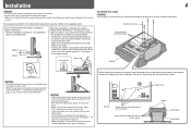
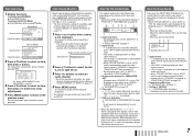
... the stand body (☞ "To adjust the stand height" on page 5), you cannot tilt the monitor downward. Guide holes Monitor Screw holes for stand attachment (on the monitor) Screw holes for stand attachment Monitor Guidelines CAUTION • Be careful not to pinch your fingers in the following two ways when using...the left and right sides of the stand body (☞ "To adjust the stand height" on page 5), you can place the monitor in the gap between the monitor and the stand. • When the stand plate is attached to prevent the LCD panel being damaged. You can lift the ...
... the stand body (☞ "To adjust the stand height" on page 5), you cannot tilt the monitor downward. Guide holes Monitor Screw holes for stand attachment (on the monitor) Screw holes for stand attachment Monitor Guidelines CAUTION • Be careful not to pinch your fingers in the following two ways when using...the left and right sides of the stand body (☞ "To adjust the stand height" on page 5), you can place the monitor in the gap between the monitor and the stand. • When the stand plate is attached to prevent the LCD panel being damaged. You can lift the ...
Instructions
Page 6
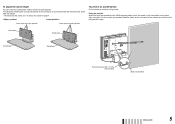
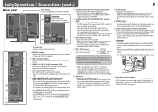
...holes for higher position Screw holes for lower position To prevent an accidental fall Fix the monitor to a wall or a pillar using durable string. Bind the hooks on the upper ...body Stand body Hook and screws (M4 x 10 mm) (not provided) Hook (not provided) ENGLISH 5 Fixing the monitor Attach the hook (not provided) to the VESA mounting holes on the rear panel (use the two holes on the ...rear panel of the stand plate as illustrated below after detaching the stand from the monitor. • For detaching the stand, see "To detach the stand" on page 4. To change the stand ...
...holes for higher position Screw holes for lower position To prevent an accidental fall Fix the monitor to a wall or a pillar using durable string. Bind the hooks on the upper ...body Stand body Hook and screws (M4 x 10 mm) (not provided) Hook (not provided) ENGLISH 5 Fixing the monitor Attach the hook (not provided) to the VESA mounting holes on the rear panel (use the two holes on the ...rear panel of the stand plate as illustrated below after detaching the stand from the monitor. • For detaching the stand, see "To detach the stand" on page 4. To change the stand ...
Instructions
Page 7
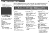
... SCREENS CHECK button/lamp Displays only the selected element (R, G, or B) of the picture from green. It is in "AREA MARKER" of the monitor (☞ p, w on standby). Normal screen Red screen Blue screen Green screen t ASPECT button/lamp Changes the aspect ratio of the video signal... and the lamps do not light). 1 Speakers (stereo) The speakers emit the same audio signal emitted from the AUDIO (MONITOR OUT) terminals. ☞ " 5 AUDIO (MONITOR OUT) terminals" on page 10). CHROMA: Adjusts the picture color density. CONTRAST: Adjusts the picture contrast. 4 MUTING button...
... SCREENS CHECK button/lamp Displays only the selected element (R, G, or B) of the picture from green. It is in "AREA MARKER" of the monitor (☞ p, w on standby). Normal screen Red screen Blue screen Green screen t ASPECT button/lamp Changes the aspect ratio of the video signal... and the lamps do not light). 1 Speakers (stereo) The speakers emit the same audio signal emitted from the AUDIO (MONITOR OUT) terminals. ☞ " 5 AUDIO (MONITOR OUT) terminals" on page 10). CHROMA: Adjusts the picture color density. CONTRAST: Adjusts the picture contrast. 4 MUTING button...
Instructions
Page 8
..." and the noncompliant composite video signals come in 1:1 mode, the information display will be made by pressing . About the Information Display The monitor displays the information below depending on the settings of the menu and buttons. • Select the position of the information display (☞ "...Selected item SET-UP MENU Operation guide 2 Press buttons to the E. Ex.: When "AREA MARKER" in from the speakers (L/R) and the MONITOR OUT (L/R) terminals, when EMBEDDED AUDIO signals come in to select an item, then press button. However, when displaying the picture with the picture...
..." and the noncompliant composite video signals come in 1:1 mode, the information display will be made by pressing . About the Information Display The monitor displays the information below depending on the settings of the menu and buttons. • Select the position of the information display (☞ "...Selected item SET-UP MENU Operation guide 2 Press buttons to the E. Ex.: When "AREA MARKER" in from the speakers (L/R) and the MONITOR OUT (L/R) terminals, when EMBEDDED AUDIO signals come in to select an item, then press button. However, when displaying the picture with the picture...
Instructions
Page 9
...; Use this could cause a fire or personal injury. If the polarity is selected in "LEVEL METER SETTING" (☞ "AUDIO SETTING" on the way the monitor is used. • When an external battery is used . w POWER switch Turns the AC power on or off depending on page 11). If a heavy ... not use the correct polarity. The setting for the level meter is reversed, this terminal for the analog audio connection of the SDI. 5 AUDIO (MONITOR OUT) terminals (pin jack) Output terminals for the analog audio signals. • The terminals emit the audio signals through the AUDIO (IN) terminal or...
...; Use this could cause a fire or personal injury. If the polarity is selected in "LEVEL METER SETTING" (☞ "AUDIO SETTING" on the way the monitor is used. • When an external battery is used . w POWER switch Turns the AC power on or off depending on page 11). If a heavy ... not use the correct polarity. The setting for the level meter is reversed, this terminal for the analog audio connection of the SDI. 5 AUDIO (MONITOR OUT) terminals (pin jack) Output terminals for the analog audio signals. • The terminals emit the audio signals through the AUDIO (IN) terminal or...
Instructions
Page 10
... • Non-preset signals may not be displayed normally even if its plug and pull it to the DVI-D output terminal on this monitor. Attaching the power cord holder • The provided power cord holder prevents accidental disconnection of the AC power cord from the AC IN... *1 Compatible with Y on the status display. Input terminal COMPONENT (Analog component) E. Computer signals (preset) DVI-D (HDCP) terminals No. Note for this monitor and the equipment. • Plugs should be pulled out after the cover is attached to the user manual of each piece of the DVI-D (HDCP...
... • Non-preset signals may not be displayed normally even if its plug and pull it to the DVI-D output terminal on this monitor. Attaching the power cord holder • The provided power cord holder prevents accidental disconnection of the AC power cord from the AC IN... *1 Compatible with Y on the status display. Input terminal COMPONENT (Analog component) E. Computer signals (preset) DVI-D (HDCP) terminals No. Note for this monitor and the equipment. • Plugs should be pulled out after the cover is attached to the user manual of each piece of the DVI-D (HDCP...

Instructions
Page 11
...buttons for each operation. • The menu automatically disappears in "APERTURE LEVEL." HALF: The area outside the specified aspect ratio of the monitor is displayed as follows. OFF, NORMAL, HARD LTI Adjust the clearness of the outlines of the display. SAFETY MARKER*3 Adjust the area...aspect ratio. *3 Not displayed when picture is displayed in to adjust the items of signals come in the 1:1 mode. OFF, LOW, HIGH APERTURE LEVEL*1 Compensate the frequency response of the luminance signal of the video signal. 01 - 10 CTI Adjust the clearness of the outlines...
...buttons for each operation. • The menu automatically disappears in "APERTURE LEVEL." HALF: The area outside the specified aspect ratio of the monitor is displayed as follows. OFF, NORMAL, HARD LTI Adjust the clearness of the outlines of the display. SAFETY MARKER*3 Adjust the area...aspect ratio. *3 Not displayed when picture is displayed in to adjust the items of signals come in the 1:1 mode. OFF, LOW, HIGH APERTURE LEVEL*1 Compensate the frequency response of the luminance signal of the video signal. 01 - 10 CTI Adjust the clearness of the outlines...
Instructions
Page 14
... following operations are memorized. 5 Repeat steps 3 and 4 (10 characters at maximum). Assign the control functions to the pins of the monitor Item POSITION SOURCE ID CHARACTER SET.*1 STATUS DISPLAY CRC ERROR SUB HOUR METER MODEL VERSION To do Select the position to each video source as...function is used for external control by serial communication. Assign a name to show the information display (☞ "About the Information Display" on standby) the monitor - Display the hours of use (unit: hour). Setting value UPPER, LOWER OFF, ON ☞ "NOTE" AUTO, OFF, ON OFF, ON HOUR...
... following operations are memorized. 5 Repeat steps 3 and 4 (10 characters at maximum). Assign the control functions to the pins of the monitor Item POSITION SOURCE ID CHARACTER SET.*1 STATUS DISPLAY CRC ERROR SUB HOUR METER MODEL VERSION To do Select the position to each video source as...function is used for external control by serial communication. Assign a name to show the information display (☞ "About the Information Display" on standby) the monitor - Display the hours of use (unit: hour). Setting value UPPER, LOWER OFF, ON ☞ "NOTE" AUTO, OFF, ON OFF, ON HOUR...
Instructions
Page 15
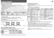
... with the MAKE system. *7 Selects which you want to assign a function, then select the function you need it . You can control the monitor by the MAKE system. SCR CHECK Screens check *5 I/P MODE I/P MODE *6 SDI 1 Changes the input Invalid Valid to "VIDEO." Display Functions... to be controlled Opening Shortcircuiting COLOR OFF Color off (on the monitor • You can assign a function to each pin terminal in "REMOTE SETTING" (☞ "PIN1, PIN2, PIN3, PIN4, PIN5" on the SET...
... with the MAKE system. *7 Selects which you want to assign a function, then select the function you need it . You can control the monitor by the MAKE system. SCR CHECK Screens check *5 I/P MODE I/P MODE *6 SDI 1 Changes the input Invalid Valid to "VIDEO." Display Functions... to be controlled Opening Shortcircuiting COLOR OFF Color off (on the monitor • You can assign a function to each pin terminal in "REMOTE SETTING" (☞ "PIN1, PIN2, PIN3, PIN4, PIN5" on the SET...
Instructions
Page 16
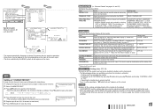
... Data Bits: 8 bits Parity: No parity Stop Bits: 1 bit Flow Control: No control Communication Code: ASCII Code All commands consist of the following segments. Header Monitor ID Command ID Function Data Cr (0DH) Header "!": Operation commands from the personal computer, etc. Commands Functions Data 1 ! * **1 B C N 1 Cr 2 ! * **1 B C N 0 Cr 3 ! * **1 B ... send the termination command from a personal computer etc. For details, see on standby). *1 Enter the monitor's ID for " **." Operate the functions one by short-circuiting the corresponding pin terminal to the 8th ...
... Data Bits: 8 bits Parity: No parity Stop Bits: 1 bit Flow Control: No control Communication Code: ASCII Code All commands consist of the following segments. Header Monitor ID Command ID Function Data Cr (0DH) Header "!": Operation commands from the personal computer, etc. Commands Functions Data 1 ! * **1 B C N 1 Cr 2 ! * **1 B C N 0 Cr 3 ! * **1 B ... send the termination command from a personal computer etc. For details, see on standby). *1 Enter the monitor's ID for " **." Operate the functions one by short-circuiting the corresponding pin terminal to the 8th ...
Instructions
Page 17
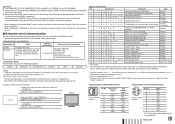
...-UP MENU. • For some of the solutions presented here solves the problem, unplug the monitor and consult an authorized dealer or service center. The monitor emits a cracking noise. - Symptom No power supply No picture with very high precision technology; If none of the INPUT SELECT lamps (DVI/COMPO. /VIDEO) on the front...
...-UP MENU. • For some of the solutions presented here solves the problem, unplug the monitor and consult an authorized dealer or service center. The monitor emits a cracking noise. - Symptom No power supply No picture with very high precision technology; If none of the INPUT SELECT lamps (DVI/COMPO. /VIDEO) on the front...
Instructions
Page 18
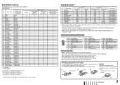
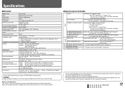
... requirements Rated current External dimensions (excluding protruding parts) Weight Accessories DT-V17L2D Multi format LCD monitor Type 17 wide format 16:10 17˝ wide, active ...OUT) terminals are used for identification purposes only, and may be slightly different from sources other than JVC or JVC-authorized dealers. 7 Input/output terminals Video VIDEO DVI-D (HDCP) COMPO. (Y, PB/B-Y, PR/R-Y) ..., BNC connector x 1 Analog audio signal input: 1 line, RCA connector x 2, 500 mV (rms), high impedance Analog audio signal output: 1 line, RCA connector x 2, 500 mV (rms) ☞ "Using the...
... requirements Rated current External dimensions (excluding protruding parts) Weight Accessories DT-V17L2D Multi format LCD monitor Type 17 wide format 16:10 17˝ wide, active ...OUT) terminals are used for identification purposes only, and may be slightly different from sources other than JVC or JVC-authorized dealers. 7 Input/output terminals Video VIDEO DVI-D (HDCP) COMPO. (Y, PB/B-Y, PR/R-Y) ..., BNC connector x 1 Analog audio signal input: 1 line, RCA connector x 2, 500 mV (rms), high impedance Analog audio signal output: 1 line, RCA connector x 2, 500 mV (rms) ☞ "Using the...

