Instruction Manual
Page 1
LCT1424-001A which is located on the rear of the cabinet. MULTI-FORMAT MONITOR DT-V1910CG DT-V1710CG INSTRUCTIONS For Customer Use: Enter below the Serial No. Model No. : DT-V1910CG/DT-V1710CG Serial No. : MUTING VOLUME UNDER DEGAUSS SCAN PULSE CROSS COLOR OFF MENU SCREENS ASPECT AREA CHECK MARKER SLOT 1 SLOT 2 SLOT 3 A B C D E F INPUT SELECT POWER The illustration shows the DT-V1910CG with provided wide mask attached. Retain this information for future reference.
LCT1424-001A which is located on the rear of the cabinet. MULTI-FORMAT MONITOR DT-V1910CG DT-V1710CG INSTRUCTIONS For Customer Use: Enter below the Serial No. Model No. : DT-V1910CG/DT-V1710CG Serial No. : MUTING VOLUME UNDER DEGAUSS SCAN PULSE CROSS COLOR OFF MENU SCREENS ASPECT AREA CHECK MARKER SLOT 1 SLOT 2 SLOT 3 A B C D E F INPUT SELECT POWER The illustration shows the DT-V1910CG with provided wide mask attached. Retain this information for future reference.
Instruction Manual
Page 2
...soft cloth. These limits are no longer be operated. There can generate picture noise and instability. ● Keep the monitor clean by JVC could deform the cabinet or cause the performance of internal components to radio communications. SCREEN BURN ● It is ...DT-V1910CG and DT-V1710CG with input cards installed. Ⅵ HANDLING ● Avoid shocks or vibrations. WARNINGS To prevent fire or shock hazard, do not attempt to high temperatures. For your community due to service it to malfunction. ● Do not block the ventilation slots. ● Do not expose this monitor...
...soft cloth. These limits are no longer be operated. There can generate picture noise and instability. ● Keep the monitor clean by JVC could deform the cabinet or cause the performance of internal components to radio communications. SCREEN BURN ● It is ...DT-V1910CG and DT-V1710CG with input cards installed. Ⅵ HANDLING ● Avoid shocks or vibrations. WARNINGS To prevent fire or shock hazard, do not attempt to high temperatures. For your community due to service it to malfunction. ● Do not block the ventilation slots. ● Do not expose this monitor...
Instruction Manual
Page 3
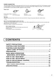
... cord only The plug on the United Kingdom power cord has a built-in the illustration.) Fuse CONTENTS SAFETY PRECAUTIONS 2 CONTROLS AND FEATURES 4 CONTROLS AND FEATURES (INPUT CARD: OPTIONAL 7 PREPARATION 11 BASIC MENU OPERATIONS (MAIN MENU, SETUP MENU 13 HOW TO USE "MAIN MENU 15 HOW TO USE "SETUP MENU 18 HOW...
... cord only The plug on the United Kingdom power cord has a built-in the illustration.) Fuse CONTENTS SAFETY PRECAUTIONS 2 CONTROLS AND FEATURES 4 CONTROLS AND FEATURES (INPUT CARD: OPTIONAL 7 PREPARATION 11 BASIC MENU OPERATIONS (MAIN MENU, SETUP MENU 13 HOW TO USE "MAIN MENU 15 HOW TO USE "SETUP MENU 18 HOW...
Instruction Manual
Page 4
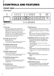
...the "FUNCTION SETTING" setup menu or MAKE/TRIGGER in the "E.AUDIO GROUP" of DT-V1910CG shown) MUTING VOLUME UNDER DEGAUSS SCAN PULSE CROSS COLOR OFF MENU SCREENS ASPECT AREA CHECK MARKER SLOT 1 SLOT 2 SLOT 3 A B C D E F INPUT SELECT 6 9 6 10 15 16 17 POWER 1 Tally lamp Lights when the... channels correspond with the group selected in the REMOTE (external control) terminal setup menu. Pressing the button again allows you to change the input sound channel. • When the button is pressed, the next highest channel is selected. • When the button is pressed, the...
...the "FUNCTION SETTING" setup menu or MAKE/TRIGGER in the "E.AUDIO GROUP" of DT-V1910CG shown) MUTING VOLUME UNDER DEGAUSS SCAN PULSE CROSS COLOR OFF MENU SCREENS ASPECT AREA CHECK MARKER SLOT 1 SLOT 2 SLOT 3 A B C D E F INPUT SELECT 6 9 6 10 15 16 17 POWER 1 Tally lamp Lights when the... channels correspond with the group selected in the REMOTE (external control) terminal setup menu. Pressing the button again allows you to change the input sound channel. • When the button is pressed, the next highest channel is selected. • When the button is pressed, the...

Instruction Manual
Page 5
...button lights and the screen is reduced (under -scan mode. 18 INPUT SELECT button Selects an input signal from VIDEO 2(INPUT SELECT B/D/F). *2 Notes • "NO SYNC" is displayed when no input card inserted in the monitor's card slots (SLOT1 - NOTE: This function is pressed while ...; When the COLOR OFF button is pressed while lit, the light goes off and the normal screen is OFF. INPUT C Selected input VIDEO Input card status (*1) NTSC Signal format (*2) HIGH Setting of "COLOR TEMP." (*3) EXT SYNC External synchronization (*4) *1 Notes • "NO SLOT" is displayed when...
...button lights and the screen is reduced (under -scan mode. 18 INPUT SELECT button Selects an input signal from VIDEO 2(INPUT SELECT B/D/F). *2 Notes • "NO SYNC" is displayed when no input card inserted in the monitor's card slots (SLOT1 - NOTE: This function is pressed while ...; When the COLOR OFF button is pressed while lit, the light goes off and the normal screen is OFF. INPUT C Selected input VIDEO Input card status (*1) NTSC Signal format (*2) HIGH Setting of "COLOR TEMP." (*3) EXT SYNC External synchronization (*4) *1 Notes • "NO SLOT" is displayed when...
Instruction Manual
Page 6
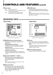
...to the terminal. SLOT 3) Optional input cards can be controlled by closing the circuit (point of contact) connected to prevent accidental disconnection of DT-V1910CG shown) 21 REMOTE (external control) terminals Terminals for details. 25 Built-in yellow and the monitor enters the stand-by mode). ...When the main power is not possible to input video or audio signals to the monitor when no input cards are not ...
...to the terminal. SLOT 3) Optional input cards can be controlled by closing the circuit (point of contact) connected to prevent accidental disconnection of DT-V1910CG shown) 21 REMOTE (external control) terminals Terminals for details. 25 Built-in yellow and the monitor enters the stand-by mode). ...When the main power is not possible to input video or audio signals to the monitor when no input cards are not ...

Instruction Manual
Page 7
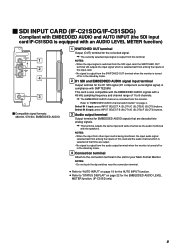
... OUT terminals are bridge-connected. 4 Connection terminal Attach to the connection terminal of your Multi-Format Monitor. 7 NOTES: • When an external synchronized signal is input, external synchronization is prioritized for both VIDEO 1 and VIDEO 2. • External synchronization does not... signal has priority over the video signal. 3 Synchronized signal input/output terminals (for both VIDEO 1 and VIDEO 2) Input (IN) and output (OUT) terminals for the composite video signals of your Multi-Format Monitor. Ⅵ VIDEO INPUT CARD (IF-C01PNG) VIDEO 1 IN OUT VIDEO 2 1...
... OUT terminals are bridge-connected. 4 Connection terminal Attach to the connection terminal of your Multi-Format Monitor. 7 NOTES: • When an external synchronized signal is input, external synchronization is prioritized for both VIDEO 1 and VIDEO 2. • External synchronization does not... signal has priority over the video signal. 3 Synchronized signal input/output terminals (for both VIDEO 1 and VIDEO 2) Input (IN) and output (OUT) terminals for the composite video signals of your Multi-Format Monitor. Ⅵ VIDEO INPUT CARD (IF-C01PNG) VIDEO 1 IN OUT VIDEO 2 1...
Instruction Manual
Page 8
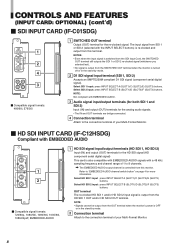
...The IN and OUT terminals are bridge-connected. 4 Connection terminal Attach to the connection terminal of your Multi-Format Monitor. Ⅵ HD SDI INPUT CARD (IF-C12HSDG) Compliant with a 48 kHz sampling frequency and channel range of 1 to the connection terminal of your... Multi-Format Monitor. 8 Select HD SDI 2 input : press INPUT SELECT B (SLOT1)/D (SLOT2)/F (SLOT3) buttons. The input signal from the OUT terminal when the monitor's power is also compatible with EMBEDDED AUDIO signals with EMBEDDED AUDIO E.AUDIO ...
...The IN and OUT terminals are bridge-connected. 4 Connection terminal Attach to the connection terminal of your Multi-Format Monitor. Ⅵ HD SDI INPUT CARD (IF-C12HSDG) Compliant with a 48 kHz sampling frequency and channel range of 1 to the connection terminal of your... Multi-Format Monitor. 8 Select HD SDI 2 input : press INPUT SELECT B (SLOT1)/D (SLOT2)/F (SLOT3) buttons. The input signal from the OUT terminal when the monitor's power is also compatible with EMBEDDED AUDIO signals with EMBEDDED AUDIO E.AUDIO ...
Instruction Manual
Page 9
... at that are output. • No signal is output from the SWITCHED OUT terminal when the monitor is being monitored, the input audio signal selected last from among the inputs on this terminal. Select IN 1 input: press INPUT SELECT A (SLOT1)/C (SLOT2)/E (SLOT3) buttons. NOTES: • Do not touch the dip... terminal. ● Refer to "AUTO INPUT" on page 22 for your Multi-Format Monitor. Refer to "STATUS DISPLAY" on page 19 for EMBEDDED AUDIO signals that time are decoded into analog signals. NOTES: • When the input from other input card is turned off or in the ...
... at that are output. • No signal is output from the SWITCHED OUT terminal when the monitor is being monitored, the input audio signal selected last from among the inputs on this terminal. Select IN 1 input: press INPUT SELECT A (SLOT1)/C (SLOT2)/E (SLOT3) buttons. NOTES: • Do not touch the dip... terminal. ● Refer to "AUTO INPUT" on page 22 for your Multi-Format Monitor. Refer to "STATUS DISPLAY" on page 19 for EMBEDDED AUDIO signals that time are decoded into analog signals. NOTES: • When the input from other input card is turned off or in the ...
Instruction Manual
Page 10
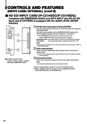
...the EMBEDDED AUDIO LEVEL METER function. (IF-C51HSDG only) 10 OUT terminal: The relocked input signal is output from this monitor. This terminal outputs the same input and same channel as the audio monitored with the speakers. 3 Connection terminal Attach to "EMBEDDED AUDIO channel switch button" on page... terminal in the stand-by mode. 2 Audio output terminal Output terminal for the AUTO INPUT function. ● Refer to 8 channels. NOTE: • Signals cannot be output from the OUT terminal when the monitor's power is OFF or in the slot of 1 to "STATUS DISPLAY" on page ...
...the EMBEDDED AUDIO LEVEL METER function. (IF-C51HSDG only) 10 OUT terminal: The relocked input signal is output from this monitor. This terminal outputs the same input and same channel as the audio monitored with the speakers. 3 Connection terminal Attach to "EMBEDDED AUDIO channel switch button" on page... terminal in the stand-by mode. 2 Audio output terminal Output terminal for the AUTO INPUT function. ● Refer to 8 channels. NOTE: • Signals cannot be output from the OUT terminal when the monitor's power is OFF or in the slot of 1 to "STATUS DISPLAY" on page ...
Instruction Manual
Page 11
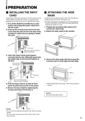
... IN OUT 3. Before mounting the monitor or connecting other equipment to the monitor, be attached to the monitor after the monitor is mounted in a rack. Mount the wide mask before installing the monitor in so that its front panel touches the monitor's rear panel. 5. Insert the Input Card's board (greencolored) into the... power and unplug the power cable from the slot (on the top and bottom of the DT-V1910CG Multi-Format Monitor 3. Secure the wide mask with the monitor. Push the Input Card in a rack. 1. This changes the viewable screen area to the 16:9 aspect ratio. • The wide ...
... IN OUT 3. Before mounting the monitor or connecting other equipment to the monitor, be attached to the monitor after the monitor is mounted in a rack. Mount the wide mask before installing the monitor in so that its front panel touches the monitor's rear panel. 5. Insert the Input Card's board (greencolored) into the... power and unplug the power cable from the slot (on the top and bottom of the DT-V1910CG Multi-Format Monitor 3. Secure the wide mask with the monitor. Push the Input Card in a rack. 1. This changes the viewable screen area to the 16:9 aspect ratio. • The wide ...
Instruction Manual
Page 13
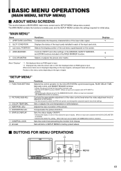
Displays *1 *2 *1 About "Displays" *1 : Not displayed when an RGB signal is input. *2 : Displayed only when the screen ratio is installed.) Sets the control lock preventing the monitor from misuse. ADJ. 5 DISTORTION ADJ. 6 STATUS DISPLAY 7 CONTROL LOCK 8 all items in the AREA MARKER function. 5 COLOR ... tally lamp colors, and MAKE/TRIGGER terminal. * Checks the amount of time that the monitor has been used. * Sets the AUTO INPUT function ON/OFF. (When an input card compliant with AUTO INPUT is installed.) * Selects the audio channel group for initial setup. Adjusts the size or...
Displays *1 *2 *1 About "Displays" *1 : Not displayed when an RGB signal is input. *2 : Displayed only when the screen ratio is installed.) Sets the control lock preventing the monitor from misuse. ADJ. 5 DISTORTION ADJ. 6 STATUS DISPLAY 7 CONTROL LOCK 8 all items in the AREA MARKER function. 5 COLOR ... tally lamp colors, and MAKE/TRIGGER terminal. * Checks the amount of time that the monitor has been used. * Sets the AUTO INPUT function ON/OFF. (When an input card compliant with AUTO INPUT is installed.) * Selects the audio channel group for initial setup. Adjusts the size or...
Instruction Manual
Page 15
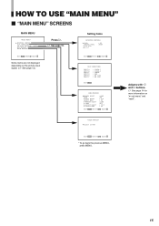
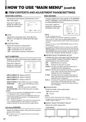
sub menu reset : 00 :HIGH EXIT:MENU ADJUST:- + SELECT: INPUT A INPUT B INPUT C INPUT D INPUT E INPUT F : VIDEO-1 : VIDEO-2 : COMPO. : RGB : NO SLOT : NO SLOT EXIT:MENU MARKER SELECT ZOOM ASPECT SELECT SAFETY AREA R-MARKER SELECT R-ZOOM R-ASPECT SELECT R-SAFETY AREA :LINE ...:ON : 4:3 : 85 :LINE :OFF : 13:9 : 85 EXIT:MENU ADJUST:- + SELECT: Adjusts with and buttons. ੬ See page 14 for more information on the picture input signal. (੬ See page 13.) Press . ੬ See page 16. SELECT :ITU601 EXIT:MENU ADJUST:- + SELECT: * To go back the previous MENU, press MENU. 15...
sub menu reset : 00 :HIGH EXIT:MENU ADJUST:- + SELECT: INPUT A INPUT B INPUT C INPUT D INPUT E INPUT F : VIDEO-1 : VIDEO-2 : COMPO. : RGB : NO SLOT : NO SLOT EXIT:MENU MARKER SELECT ZOOM ASPECT SELECT SAFETY AREA R-MARKER SELECT R-ZOOM R-ASPECT SELECT R-SAFETY AREA :LINE ...:ON : 4:3 : 85 :LINE :OFF : 13:9 : 85 EXIT:MENU ADJUST:- + SELECT: Adjusts with and buttons. ੬ See page 14 for more information on the picture input signal. (੬ See page 13.) Press . ੬ See page 16. SELECT :ITU601 EXIT:MENU ADJUST:- + SELECT: * To go back the previous MENU, press MENU. 15...
Instruction Manual
Page 16
... frequency characteristics of SLOT3 VIDEO-1/VIDEO-2 : With VIDEO input card is installed. LEVEL CONTROL FREQ. HIGH: Compensates the high frequencies. INPUT A INPUT B INPUT C INPUT D INPUT E INPUT F : VIDEO-1 : VIDEO-2 : COMPO. : RGB : NO SLOT : NO SLOT EXIT: MENU INPUT A/INPUT B : Status of SLOT1 INPUT C/INPUT D : Status of SLOT2 INPUT E/INPUT F : Status of the input video signal. SDI1/SDI2 : With SDI input card is installed. HD SDI1/HD SDI2 : With...
... frequency characteristics of SLOT3 VIDEO-1/VIDEO-2 : With VIDEO input card is installed. LEVEL CONTROL FREQ. HIGH: Compensates the high frequencies. INPUT A INPUT B INPUT C INPUT D INPUT E INPUT F : VIDEO-1 : VIDEO-2 : COMPO. : RGB : NO SLOT : NO SLOT EXIT: MENU INPUT A/INPUT B : Status of SLOT1 INPUT C/INPUT D : Status of SLOT2 INPUT E/INPUT F : Status of the input video signal. SDI1/SDI2 : With SDI input card is installed. HD SDI1/HD SDI2 : With...
Instruction Manual
Page 17
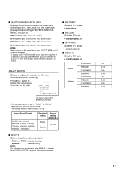
... R-Y PHASE R/B GAIN G-Y PHASE G/B GAIN R-Y PHASE R/B GAIN G-Y PHASE G/B GAIN 90 0.79 244 0.45 90 0.86 244 0.30 17 NOTES: • When a picture of 4:3 aspect ratio is input, SAFETY AREA for 4:3 screen is displayed. • To display SAFETY AREA for 16:9 screen ratio when a picture of 16:9 aspect ratio is ITU709... Input Signal Format NTSC, PAL, 480/60i, 480/60p, 576/50i, 575/50p 720/60p, 1080/50i, 1080/60i, 1035/60i, 1080/24psF Standard Manual setting ...
... R-Y PHASE R/B GAIN G-Y PHASE G/B GAIN R-Y PHASE R/B GAIN G-Y PHASE G/B GAIN 90 0.79 244 0.45 90 0.86 244 0.30 17 NOTES: • When a picture of 4:3 aspect ratio is input, SAFETY AREA for 4:3 screen is displayed. • To display SAFETY AREA for 16:9 screen ratio when a picture of 16:9 aspect ratio is ITU709... Input Signal Format NTSC, PAL, 480/60i, 480/60p, 576/50i, 575/50p 720/60p, 1080/50i, 1080/60i, 1035/60i, 1080/24psF Standard Manual setting ...
Instruction Manual
Page 18
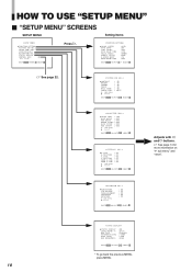
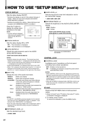
SIZE/POSI.ADJ. COLOR SYSTEM AUTO INPUT SYNC SELECT RUSH DELAY TIME TALLY SELECT REMOTE SYSTEM E.AUDIO GROUP HOUR METER X100 :AUTO :ON :INT. :STD. :GREEN :MAKE :1G :000 EXIT:MENU ADJUST:- + ... : 00 EXIT:MENU ADJUST:- + SELECT: 18 STATUS DISPLAY LEVEL METER ch BAR TYPE REFERENCE LEVEL OVER LEVEL BAR BRIGHTNESS :ON :31 24 :3COLORS :-20dB :-4dB :HIGH EXIT:MENU ADJUST:- + SELECT: * To go back the previous MENU, press MENU. STATUS DISPLAY CONTROL LOCK all reset :ON EXIT:MENU ENTER:+ SELECT: Press . HOW...
SIZE/POSI.ADJ. COLOR SYSTEM AUTO INPUT SYNC SELECT RUSH DELAY TIME TALLY SELECT REMOTE SYSTEM E.AUDIO GROUP HOUR METER X100 :AUTO :ON :INT. :STD. :GREEN :MAKE :1G :000 EXIT:MENU ADJUST:- + ... : 00 EXIT:MENU ADJUST:- + SELECT: 18 STATUS DISPLAY LEVEL METER ch BAR TYPE REFERENCE LEVEL OVER LEVEL BAR BRIGHTNESS :ON :31 24 :3COLORS :-20dB :-4dB :HIGH EXIT:MENU ADJUST:- + SELECT: * To go back the previous MENU, press MENU. STATUS DISPLAY CONTROL LOCK all reset :ON EXIT:MENU ENTER:+ SELECT: Press . HOW...
Instruction Manual
Page 19
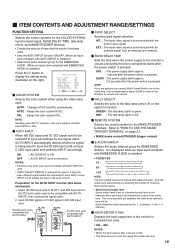
... MAKE/TRIGGER terminal. • Checks the amount of time that the monitor has been used . • "INPUT SELECT ERROR" is pressed. However, if the input signal is unstable, select NTSC or PAL. Ⅵ AUTO INPUT When HD SDI signal and D1 SDI signal need to 000. •...Ⅵ E.AUDIO GROUP Selects the audio channel group for approx. 3 seconds when different signal cables are connected to each INPUT A and INPUT C and signals are input to the monitor's circuits (excluding the micro computers) starts after the power switch is displayed for EMBEDDED AUDIO. NOTES: • Functions ...
... MAKE/TRIGGER terminal. • Checks the amount of time that the monitor has been used . • "INPUT SELECT ERROR" is pressed. However, if the input signal is unstable, select NTSC or PAL. Ⅵ AUTO INPUT When HD SDI signal and D1 SDI signal need to 000. •...Ⅵ E.AUDIO GROUP Selects the audio channel group for approx. 3 seconds when different signal cables are connected to each INPUT A and INPUT C and signals are input to the monitor's circuits (excluding the micro computers) starts after the power switch is displayed for EMBEDDED AUDIO. NOTES: • Functions ...
Instruction Manual
Page 20
...signal. NOTE : COMPO. Press the button to display the setting menu illustrated on the right. HIGH : Sets the color temperature to make fine adjustments between the monitors. When the PAL signal is input, only CONTRAST and BRIGHT are displayed. CONTRAST BRIGHT CHROMA PHASE NTSC SETUP COMPO.LEVEL sub menu ...SMPTE : Compliant with Betacam 0% set -up signal. LEVEL is displayed only when a 480/60i, 480/60p, 576/ 50i or 576/50p signal is input. Ⅵ COMPO. B00 : Compliant with M2VTR signals. COLOR TEMP. HOW TO USE "SETUP MENU" (cont'd) PICTURE SUB ADJ. Sets or adjusts the...
...signal. NOTE : COMPO. Press the button to display the setting menu illustrated on the right. HIGH : Sets the color temperature to make fine adjustments between the monitors. When the PAL signal is input, only CONTRAST and BRIGHT are displayed. CONTRAST BRIGHT CHROMA PHASE NTSC SETUP COMPO.LEVEL sub menu ...SMPTE : Compliant with Betacam 0% set -up signal. LEVEL is displayed only when a 480/60i, 480/60p, 576/ 50i or 576/50p signal is input. Ⅵ COMPO. B00 : Compliant with M2VTR signals. COLOR TEMP. HOW TO USE "SETUP MENU" (cont'd) PICTURE SUB ADJ. Sets or adjusts the...
Instruction Manual
Page 22
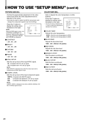
... the right side of the screen. • AUDIO LEVEL METER is not displayed when this is set to OFF. • When "1-8" is selected, the channel input level for 1, 2, 3 and 4 is displayed on the right. WHITE-1 : White color display WHITE-2 : White (half transparent) display 3 COLORS : The ... TYPE REFERENCE LEVEL OVER LEVEL BAR BRIGHTNESS : ON :31•24 :3COLORS : -20dB : -4dB : HIGH EXIT: MENU ADJUST:- + SELECT: Ⅵ STATUS DISPLAY Sets the status display ON or OFF. HIGH : Brighter LOW : Darker AUDIO LEVEL METER display example LEVEL METER ch: 1-8, BAR TYPE: 3COLORS OVER LEVEL ...
... the right side of the screen. • AUDIO LEVEL METER is not displayed when this is set to OFF. • When "1-8" is selected, the channel input level for 1, 2, 3 and 4 is displayed on the right. WHITE-1 : White color display WHITE-2 : White (half transparent) display 3 COLORS : The ... TYPE REFERENCE LEVEL OVER LEVEL BAR BRIGHTNESS : ON :31•24 :3COLORS : -20dB : -4dB : HIGH EXIT: MENU ADJUST:- + SELECT: Ⅵ STATUS DISPLAY Sets the status display ON or OFF. HIGH : Brighter LOW : Darker AUDIO LEVEL METER display example LEVEL METER ch: 1-8, BAR TYPE: 3COLORS OVER LEVEL ...
Instruction Manual
Page 23
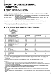
Functions to be controlled 1 Turns on the tally lamp 2 Changes the input to INPUT A 3 Changes the input to INPUT B 4 Changes the input to INPUT C 5 Changes the input to INPUT D 6 Changes the input to INPUT E 7 Changes the input to INPUT F 8 COLOR OFF 9 AREA MARKER 10 ASPECT 11 TALLY SELECT 12 AREA MARKER set-up .... 1 second) short-circuiting (short with GND of the controlled terminal. One is the RS-485 terminal, and this allows the monitor to be controlled by the MAKE(make contact system): Controls functions either by instantaneously (approx. 1 second) short-circuiting (short with GND...
Functions to be controlled 1 Turns on the tally lamp 2 Changes the input to INPUT A 3 Changes the input to INPUT B 4 Changes the input to INPUT C 5 Changes the input to INPUT D 6 Changes the input to INPUT E 7 Changes the input to INPUT F 8 COLOR OFF 9 AREA MARKER 10 ASPECT 11 TALLY SELECT 12 AREA MARKER set-up .... 1 second) short-circuiting (short with GND of the controlled terminal. One is the RS-485 terminal, and this allows the monitor to be controlled by the MAKE(make contact system): Controls functions either by instantaneously (approx. 1 second) short-circuiting (short with GND...