DT-3D24G1U Operation Manual
Page 2
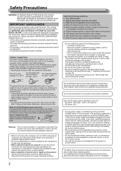
... exhibits a distinct change in performance -for future reference. • All warnings on /off the POWER switch, control the AC power supply by the manufacturer. • Do not use . • All the safety and operating instructions should be sure to direct sunlight or strong light • Do not place this apparatus from the AC mains, disconnect the power supply cord plug from the AC...
... exhibits a distinct change in performance -for future reference. • All warnings on /off the POWER switch, control the AC power supply by the manufacturer. • Do not use . • All the safety and operating instructions should be sure to direct sunlight or strong light • Do not place this apparatus from the AC mains, disconnect the power supply cord plug from the AC...
DT-3D24G1U Operation Manual
Page 3
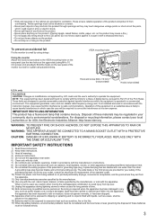
... INSTRUCTIONS 1) Read these instructions. 2) Keep these materials may be blocked or covered. • Never push objects of any ventilation openings. Fixing the monitor Attach the hook (not provided) to a wall or a pillar using durable string. Install in your local authorities or for a Class A digital device, pursuant to Part 15 of the monitor to the VESA mounting holes on or pinched particularly at his own expense. A polarized plug...
... INSTRUCTIONS 1) Read these instructions. 2) Keep these materials may be blocked or covered. • Never push objects of any ventilation openings. Fixing the monitor Attach the hook (not provided) to a wall or a pillar using durable string. Install in your local authorities or for a Class A digital device, pursuant to Part 15 of the monitor to the VESA mounting holes on or pinched particularly at his own expense. A polarized plug...
DT-3D24G1U Operation Manual
Page 4
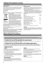
... for Users on the LCD panel. Leaving the dust around the intakes (all the openings). In this case, move the product to the applicable collection point for incorrect disposal of this product, please visit our web page http:// www.jvc.eu/ to obtain information about the following length: Cable Power cord (attached cable (H05VV-F 3 x 0.75 mm2)) Video signal cable (coaxial cable) Audio signal cable (shielded cable) DVI cable (shielded cable...
... for Users on the LCD panel. Leaving the dust around the intakes (all the openings). In this case, move the product to the applicable collection point for incorrect disposal of this product, please visit our web page http:// www.jvc.eu/ to obtain information about the following length: Cable Power cord (attached cable (H05VV-F 3 x 0.75 mm2)) Video signal cable (coaxial cable) Audio signal cable (shielded cable) DVI cable (shielded cable...
DT-3D24G1U Operation Manual
Page 5
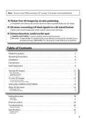
... right eyes in 3D 12 To view 3D images 13 To view existing 3D images 13 To view images taken by two cameras 13 Setting the CAMERA ASSIST MENU 14 Other 3D functions 16 SCOPE button/lamp 16 3D CURSOR button/lamp 16 Setting the menu 18 MAIN MENU 19 SET-UP MENU 23 External control 26 Troubleshooting 30 Self-check program 31 Specifications 32 Available signals 33 Dimensions 34 5
... right eyes in 3D 12 To view 3D images 13 To view existing 3D images 13 To view images taken by two cameras 13 Setting the CAMERA ASSIST MENU 14 Other 3D functions 16 SCOPE button/lamp 16 3D CURSOR button/lamp 16 Setting the menu 18 MAIN MENU 19 SET-UP MENU 23 External control 26 Troubleshooting 30 Self-check program 31 Specifications 32 Available signals 33 Dimensions 34 5
DT-3D24G1U Operation Manual
Page 6
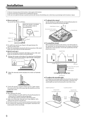
... set up 1 You can place the monitor as illustrated below. 1 Remove the screws on the sides of the stand, align the guidelines, and then reattach the screws. Cautions ● When lifting up 1" again, remove the screws on the monitor to prevent the LCD panel from being damaged. Guide holes Guides Monitor Screw holes for stand attachment Stand plate Stand body ● To adjust the stand height To change the position of the stand body. Monitor...
... set up 1 You can place the monitor as illustrated below. 1 Remove the screws on the sides of the stand, align the guidelines, and then reattach the screws. Cautions ● When lifting up 1" again, remove the screws on the monitor to prevent the LCD panel from being damaged. Guide holes Guides Monitor Screw holes for stand attachment Stand plate Stand body ● To adjust the stand height To change the position of the stand body. Monitor...
DT-3D24G1U Operation Manual
Page 7
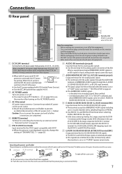
... using the DC 24V power supply (Voltage range: DC 23.3V − DC 25.5V), check the pin number, signal, and polarity of two parts: the cord case and the case cover. 1 cord case AC IN terminal 2 case cover 3 To take off the case cover ● Do not use the monitor after turning on the AC POWER switch. 3 AC IN terminal AC power input connector. is on or in "P.SAVE" (power save ) mode (→ "NO SYNC...
... using the DC 24V power supply (Voltage range: DC 23.3V − DC 25.5V), check the pin number, signal, and polarity of two parts: the cord case and the case cover. 1 cord case AC IN terminal 2 case cover 3 To take off the case cover ● Do not use the monitor after turning on the AC POWER switch. 3 AC IN terminal AC power input connector. is on or in "P.SAVE" (power save ) mode (→ "NO SYNC...
DT-3D24G1U Operation Manual
Page 9
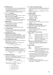
... 1/L) terminal Input from the E. Power lamp Off: Green: The power is turned off The monitor is on the monitor if the DC power is displayed Selects or adjusts menu items (→ "Menu Operations" on page 18). Disconnect the DC connector, set up in "SYNC FUNCTION") (→ page 22) ● You cannot turn the VOLUME adjustment knob. ● Muting function is equipped on page 7). 9 RGB (Normal screen) Red screen Blue screen Green screen e SCOPE button/lamp Displays/hides the...
... 1/L) terminal Input from the E. Power lamp Off: Green: The power is turned off The monitor is on the monitor if the DC power is displayed Selects or adjusts menu items (→ "Menu Operations" on page 18). Disconnect the DC connector, set up in "SYNC FUNCTION") (→ page 22) ● You cannot turn the VOLUME adjustment knob. ● Muting function is equipped on page 7). 9 RGB (Normal screen) Red screen Blue screen Green screen e SCOPE button/lamp Displays/hides the...
DT-3D24G1U Operation Manual
Page 10
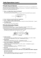
... signals come in to the SDI terminal and SDI input is selected. ● You have to the settings of each input (SDI 1/L and SDI 2/R). ● Works as SDI 1/L in MIX mode and DUAL LINK SDI input. 1 Press or button when a menu is "ANAGLYPH." 10 Use the T.C. However, the information display will overlap with higher resolution than a computer, the picture is displayed. ● The screen for audio...
... signals come in to the SDI terminal and SDI input is selected. ● You have to the settings of each input (SDI 1/L and SDI 2/R). ● Works as SDI 1/L in MIX mode and DUAL LINK SDI input. 1 Press or button when a menu is "ANAGLYPH." 10 Use the T.C. However, the information display will overlap with higher resolution than a computer, the picture is displayed. ● The screen for audio...
DT-3D24G1U Operation Manual
Page 11
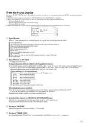
... SDI DUAL LINK input ● Displays the sampling structure/color space/pixel resolution of the signal format. ● Displayed when the 3G SDI or HD SDI DUAL LINK signal is input. 4 Setting of "MUTING" ● Displayed only when muting is activated (→ 5 on the type of input signals and their conditions. When you change the input - Status indication of DVI input → On page 25 "DVI INPUT SEL." However...
... SDI DUAL LINK input ● Displays the sampling structure/color space/pixel resolution of the signal format. ● Displayed when the 3G SDI or HD SDI DUAL LINK signal is input. 4 Setting of "MUTING" ● Displayed only when muting is activated (→ 5 on the type of input signals and their conditions. When you change the input - Status indication of DVI input → On page 25 "DVI INPUT SEL." However...
DT-3D24G1U Operation Manual
Page 14
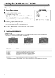
... close the menu screen. Setting the CAMERA ASSIST MENU This product is flipped horizontally. ● Select "R-H-MIRROR." Menu Operations CAMERA ASSIST MENU 1 Press the CAMERA ASSIST button. ➔ The CAMERA ASSIST MENU appears. ● Only works when the SDI input is selected and images available for camera adjustment in shooting. Setting value Content OFF Does not rotate or flip the image R-H-MIRROR R-V-MIRROR *1 Horizontally flips images input into...
... close the menu screen. Setting the CAMERA ASSIST MENU This product is flipped horizontally. ● Select "R-H-MIRROR." Menu Operations CAMERA ASSIST MENU 1 Press the CAMERA ASSIST button. ➔ The CAMERA ASSIST MENU appears. ● Only works when the SDI input is selected and images available for camera adjustment in shooting. Setting value Content OFF Does not rotate or flip the image R-H-MIRROR R-V-MIRROR *1 Horizontally flips images input into...
DT-3D24G1U Operation Manual
Page 16
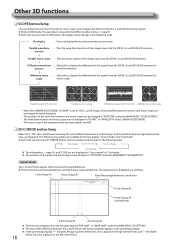
... 2/R input signals. ● Works in "POSITION" under the MAIN MENU "INFORMATION." The operation to "ON", L and R images of the parallel wave form monitor and vector scope are exchanged and then displayed. • The positions of the wave form monitor and vector scope can be performed differs in other modes. (→ page 9) ● Each time you press the 3D CURSOR button, the line display mode changes...
... 2/R input signals. ● Works in "POSITION" under the MAIN MENU "INFORMATION." The operation to "ON", L and R images of the parallel wave form monitor and vector scope are exchanged and then displayed. • The positions of the wave form monitor and vector scope can be performed differs in other modes. (→ page 9) ● Each time you press the 3D CURSOR button, the line display mode changes...
DT-3D24G1U Operation Manual
Page 18
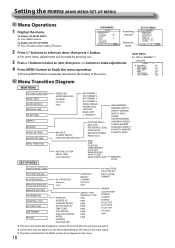
.... 4 Press MENU button to make adjustments. H POSITION ADJ. TALLY SELECT SD4:3 LARGE DIMMER REMOTE SETTING INFORMATION CONTROL LOCK DVI INPUT SEL. SDI FORMAT all reset POSITION SOURCE ID CHARACTER SET. To display the SET-UP MENU ➔ Press button while holding button. FAR LIMIT NEAR LIMIT L. To display the MAIN MENU ➔ Press MENU button. INTENSITY LEVEL METER ch BAR TYPE REFERENCE LEVEL OVER LEVEL BAR BRIGHTNESS PEAK HOLD GAIN SIZE POSITION TRANSPARENT AUTO OFF WAVE DISPLAY WAVE FILTER...
.... 4 Press MENU button to make adjustments. H POSITION ADJ. TALLY SELECT SD4:3 LARGE DIMMER REMOTE SETTING INFORMATION CONTROL LOCK DVI INPUT SEL. SDI FORMAT all reset POSITION SOURCE ID CHARACTER SET. To display the SET-UP MENU ➔ Press button while holding button. FAR LIMIT NEAR LIMIT L. To display the MAIN MENU ➔ Press MENU button. INTENSITY LEVEL METER ch BAR TYPE REFERENCE LEVEL OVER LEVEL BAR BRIGHTNESS PEAK HOLD GAIN SIZE POSITION TRANSPARENT AUTO OFF WAVE DISPLAY WAVE FILTER...
DT-3D24G1U Operation Manual
Page 19
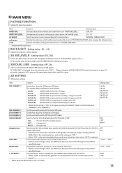
... range. Set the limit of the pop-up level in Cursor mode of "3D cursor." - 0.1% - - 4.0% • The line color changes when the difference between "FORMAT1" and "FORMAT2." BACK LIGHT Setting value: -20 - +20 Adjusts the brightness of "PICTURE FUNCTION" while viewing the actual picture. The setting values and features are displayed translucent in Grid mode of "3D cursor." *1 Works when the MIX mode is input. To take 3D images...
... range. Set the limit of the pop-up level in Cursor mode of "3D cursor." - 0.1% - - 4.0% • The line color changes when the difference between "FORMAT1" and "FORMAT2." BACK LIGHT Setting value: -20 - +20 Adjusts the brightness of "PICTURE FUNCTION" while viewing the actual picture. The setting values and features are displayed translucent in Grid mode of "3D cursor." *1 Works when the MIX mode is input. To take 3D images...
DT-3D24G1U Operation Manual
Page 22
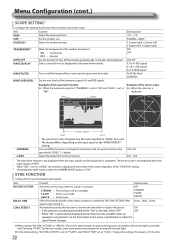
... color of the "POSITION" setting. *3 Not displayed in . Selecting "P.SAVE" (power save mode GRAY B. : Gray screen STANDBY P.SAVE GRAY B. Set the window size. WAVE FILTER Turn on /off (on the input signal or the "WAVE DISPLAY" setting. signals stop coming in MIX mode or when the CAMERA ASSIST button is off the function to "15min." SYNC FUNCTION Settings for the wave form monitor and vector scope. The vector scope is not displayed when the input signals are DVI (input...
... color of the "POSITION" setting. *3 Not displayed in . Selecting "P.SAVE" (power save mode GRAY B. : Gray screen STANDBY P.SAVE GRAY B. Set the window size. WAVE FILTER Turn on /off (on the input signal or the "WAVE DISPLAY" setting. signals stop coming in MIX mode or when the CAMERA ASSIST button is off the function to "15min." SYNC FUNCTION Settings for the wave form monitor and vector scope. The vector scope is not displayed when the input signals are DVI (input...

DT-3D24G1U Operation Manual
Page 23
... pixels. while viewing the actual picture. SET-UP MENU FUNCTION SETTING Configure the sub menu display, the lighting color of the tally lamp, the size of images, the brightness of each input. Item sub menu POSI. ON : Matches the horizontal picture size to the number of the screen. Restore the default settings for the drive levels and cutoff points of each color (red, green, and blue). R DRIVE G DRIVE B DRIVE *1 R CUT OFF G CUT OFF B CUT OFF *1 sub menu reset...
... pixels. while viewing the actual picture. SET-UP MENU FUNCTION SETTING Configure the sub menu display, the lighting color of the tally lamp, the size of images, the brightness of each input. Item sub menu POSI. ON : Matches the horizontal picture size to the number of the screen. Restore the default settings for the drive levels and cutoff points of each color (red, green, and blue). R DRIVE G DRIVE B DRIVE *1 R CUT OFF G CUT OFF B CUT OFF *1 sub menu reset...
DT-3D24G1U Operation Manual
Page 25
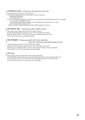
.... - VOLUME adjustment knob - Turning on/off (on the front panel. Press the button and button to display the SET-UP MENU, and set to "AUTO." (Normally, select "AUTO") ● Select "COMPO.", "RGB" or "PC" when the picture is not displayed correctly with "AUTO." ● DVI-D input of the monitor is compatible with "AUTO", select the setting value according to the input signal format. ● When "AUTO" is on, the monitor turns off (standby). 25 DVI INPUT SEL. SDI FORMAT Setting...
.... - VOLUME adjustment knob - Turning on/off (on the front panel. Press the button and button to display the SET-UP MENU, and set to "AUTO." (Normally, select "AUTO") ● Select "COMPO.", "RGB" or "PC" when the picture is not displayed correctly with "AUTO." ● DVI-D input of the monitor is compatible with "AUTO", select the setting value according to the input signal format. ● When "AUTO" is on, the monitor turns off (standby). 25 DVI INPUT SEL. SDI FORMAT Setting...
DT-3D24G1U Operation Manual
Page 27
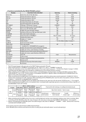
..., the display mode changes in the same way as when pressing SCREENS CHECK button (→ w on page 11 *6 Off On *7 *8 Color Off NORMAL - When "LEVEL METER ch" is set -up options will be the setting value currently selected in "SOURCE ID" ("ON" or "AUTO" [short-circuiting]) and "OFF" (opening). While controlling with the TRIGGER system, the pattern of the audio channel display is switched between displayed (short...
..., the display mode changes in the same way as when pressing SCREENS CHECK button (→ w on page 11 *6 Off On *7 *8 Color Off NORMAL - When "LEVEL METER ch" is set -up options will be the setting value currently selected in "SOURCE ID" ("ON" or "AUTO" [short-circuiting]) and "OFF" (opening). While controlling with the TRIGGER system, the pattern of the audio channel display is switched between displayed (short...
DT-3D24G1U Operation Manual
Page 30
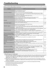
...; Adjust the picture contrast or brightness by the MAKE system do not turn on the unit. Wrong picture position, wrong ● Check whether the setting of 1:1 is set correctly. ● Adjust each picture adjustment knob on the front panel or adjust the items of this problem. Change the input or the input signal. ● The items controlled by using the INPUT SELECT buttons. ● Connect the signal cable firmly. The LCD display is not a malfunction. ● Red spots, blue spots and green spots...
...; Adjust the picture contrast or brightness by the MAKE system do not turn on the unit. Wrong picture position, wrong ● Check whether the setting of 1:1 is set correctly. ● Adjust each picture adjustment knob on the front panel or adjust the items of this problem. Change the input or the input signal. ● The items controlled by using the INPUT SELECT buttons. ● Connect the signal cable firmly. The LCD display is not a malfunction. ● Red spots, blue spots and green spots...
DT-3D24G1U Operation Manual
Page 32
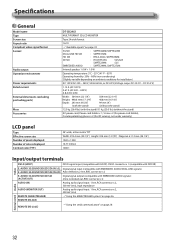
... power cord, Power cord holder × 1, Screw × 2 (for power cord holder), Circular polarizing glasses × 2 (for 3D viewing, not under warranty) LCD panel Type Effective screen size Number of pixels displayed Number of colors displayed Contrast ratio (TYP.) 24˝ wide, active matrix TFT Width: 518.4 mm (20 1/2˝) Height: 324 mm (12 7/8˝) Diagonal: 611.3 mm (24 1/4˝) 1920 × 1200 16.77 million 1000:1 Input/output terminals Video DVI-D (HDCP) DVI-D signal input (compatible with HDCP): DVI-D connector x 1 (compatible...
... power cord, Power cord holder × 1, Screw × 2 (for power cord holder), Circular polarizing glasses × 2 (for 3D viewing, not under warranty) LCD panel Type Effective screen size Number of pixels displayed Number of colors displayed Contrast ratio (TYP.) 24˝ wide, active matrix TFT Width: 518.4 mm (20 1/2˝) Height: 324 mm (12 7/8˝) Diagonal: 611.3 mm (24 1/4˝) 1920 × 1200 16.77 million 1000:1 Input/output terminals Video DVI-D (HDCP) DVI-D signal input (compatible with HDCP): DVI-D connector x 1 (compatible...
22 page technical guide on the DT-3D24G1 24-inch 3-D Monitor
Page 16
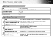
..., TXD, NC, GND, NC, RTS, CTS, and NC (Note: the 7th and 8th terminals are connected Audio External controls AUDIO 3G SDI/HD SDI/SD SDI (IN 2/R) E. SPECIFICATIONS (CONTINUED) LCD Panel Type Effective screen size: W x H x Diagonal Number of pixels displayed Number of colors displayed Contrast ratio (TYP.) 24˝ wide, active matrix TFT 518.4 x 324 x 611.3 mm (20-1/2˝ x 12-7/8˝ x 24-1/4˝) 1920 x 1200 16.77 million...
..., TXD, NC, GND, NC, RTS, CTS, and NC (Note: the 7th and 8th terminals are connected Audio External controls AUDIO 3G SDI/HD SDI/SD SDI (IN 2/R) E. SPECIFICATIONS (CONTINUED) LCD Panel Type Effective screen size: W x H x Diagonal Number of pixels displayed Number of colors displayed Contrast ratio (TYP.) 24˝ wide, active matrix TFT 518.4 x 324 x 611.3 mm (20-1/2˝ x 12-7/8˝ x 24-1/4˝) 1920 x 1200 16.77 million...

