Service Guide
Page 6
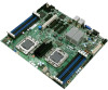
... the Intel® Server Board S5520HC/S5520HCT to the Technical Product Specification. Unless specified, features apply to navigate through the BIOS setup screen, perform a BIOS update, and reset the password or CMOS. This manual is noted in the Technical Product Specification. For the latest version of the Intel® Server Board S5520HC /S5520HCT/S5500HCV. Use this chapter for step-by-step instructions and diagrams for troubleshooting, upgrading, and repairing this manual, refer to update...
... the Intel® Server Board S5520HC/S5520HCT to the Technical Product Specification. Unless specified, features apply to navigate through the BIOS setup screen, perform a BIOS update, and reset the password or CMOS. This manual is noted in the Technical Product Specification. For the latest version of the Intel® Server Board S5520HC /S5520HCT/S5500HCV. Use this chapter for step-by-step instructions and diagrams for troubleshooting, upgrading, and repairing this manual, refer to update...
Service Guide
Page 8
... titled, "Installation and Use". Or visit: http://support.intel.com/support/motherboards/server/S5520HC/ See the section on the web page titled, "Compatibility". Available at : http://serverconfigurator.intel.com/default.aspx Chassis tested with this product Use this Document or Software Intel® Server Board S5520HC/S5520HCT and S5500HCV Technical Product Specification. Intel® Server Board S5520HC, S5520HCT, S5500HCV Quick Start User's Guide in the product box. Intel® Server Configurator tool...
... titled, "Installation and Use". Or visit: http://support.intel.com/support/motherboards/server/S5520HC/ See the section on the web page titled, "Compatibility". Available at : http://serverconfigurator.intel.com/default.aspx Chassis tested with this product Use this Document or Software Intel® Server Board S5520HC/S5520HCT and S5500HCV Technical Product Specification. Intel® Server Board S5520HC, S5520HCT, S5500HCV Quick Start User's Guide in the product box. Intel® Server Configurator tool...
Service Guide
Page 9
... Component Locations 4 Configuration Jumpers...5 Back Panel Features ...6 Intel® Light-Guided Diagnostics 7 RAID Support ...8 Hardware Requirements ...9 Processor ...9 Memory 9 Power Supply ...11 Storage Mode Matrix ...12 Optional Hardware ...14 Intel® SAS Entry RAID Module AXX4SASMOD 14 2 System Utilities 17 Using the BIOS Setup Utility 17 Starting Setup ...17 If You Cannot Access Setup 17 Setup Menus ...17 Upgrading the BIOS...18 Preparing for the Upgrade 19 Recovering the BIOS ...20 Clearing the Password...21 Clearing the CMOS...23 3 Hardware Installations and Upgrades 24...
... Component Locations 4 Configuration Jumpers...5 Back Panel Features ...6 Intel® Light-Guided Diagnostics 7 RAID Support ...8 Hardware Requirements ...9 Processor ...9 Memory 9 Power Supply ...11 Storage Mode Matrix ...12 Optional Hardware ...14 Intel® SAS Entry RAID Module AXX4SASMOD 14 2 System Utilities 17 Using the BIOS Setup Utility 17 Starting Setup ...17 If You Cannot Access Setup 17 Setup Menus ...17 Upgrading the BIOS...18 Preparing for the Upgrade 19 Recovering the BIOS ...20 Clearing the Password...21 Clearing the CMOS...23 3 Hardware Installations and Upgrades 24...

Service Guide
Page 11
... 14 Figure 9. BIOS Recover Jumper 20 Figure 10. Password Clear Jumper 22 Figure 11. Opening the Processor Socket Lever 26 Figure 14. Install the processor ...27 Figure 18. Installing Processor Heatsink(s 30 Figure 20. Locating and Removing the CMOS Battery 33 Tables Table 1. Server Board Features ...2 Table 2. Configuration Jumpers ...5 Table 3. NIC LEDs ...6 Table 4. Storage Mode Matrix ...13 Table 5. Keyboard Commands...18 Table 6. Heatsink Requirements for Compatible Intel® Server Chassis 29 Table 7. POST Error Beep Codes 34 Table 8. BIOS POST Error Beep Codes 40...
... 14 Figure 9. BIOS Recover Jumper 20 Figure 10. Password Clear Jumper 22 Figure 11. Opening the Processor Socket Lever 26 Figure 14. Install the processor ...27 Figure 18. Installing Processor Heatsink(s 30 Figure 20. Locating and Removing the CMOS Battery 33 Tables Table 1. Server Board Features ...2 Table 2. Configuration Jumpers ...5 Table 3. NIC LEDs ...6 Table 4. Storage Mode Matrix ...13 Table 5. Keyboard Commands...18 Table 6. Heatsink Requirements for Compatible Intel® Server Chassis 29 Table 7. POST Error Beep Codes 34 Table 8. BIOS POST Error Beep Codes 40...
Service Guide
Page 14
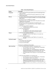
... fans (6-pin headers) ƒ One rear fan (4-pin header) 3-pin fans are compatible with all fan headers. ƒ Intel® Server Board S5520HC/S5520HCT: Six expansion slots o One PCI Express* Gen 2 slot (x16 Mechanically, x8 Electrically) o Three PCI Express* Gen 2 x8 slots o One PCI Express* Gen 1 slot (x8 Mechanically, x4 Electrically) shared with SAS Module slot. This PCI Express* Gen 1 slot is not available when the SAS module slot is in Card Slots Table 1. Server Board Features Feature Processors Memory Chipset Cooling fan support Add-in use...
... fans (6-pin headers) ƒ One rear fan (4-pin header) 3-pin fans are compatible with all fan headers. ƒ Intel® Server Board S5520HC/S5520HCT: Six expansion slots o One PCI Express* Gen 2 slot (x16 Mechanically, x8 Electrically) o Three PCI Express* Gen 2 x8 slots o One PCI Express* Gen 1 slot (x8 Mechanically, x4 Electrically) shared with SAS Module slot. This PCI Express* Gen 1 slot is not available when the SAS module slot is in Card Slots Table 1. Server Board Features Feature Processors Memory Chipset Cooling fan support Add-in use...

Service Guide
Page 15
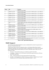
... Optical Drive Support USB Drive Support I/O control support RAID Support Management support Description ƒ Server Engine* LLC Pilot II* with 64 MB DDR2 memory, 8 MB allocated to graphics ƒ Dual video is supported ƒ Optical devices are supported ƒ Six SATA connectors at 1.5 Gbps and 3 Gbps ƒ Four SAS connectors at 3 Gbps through optional Intel® SAS Entry RAID Module AXX4SASMOD ƒ One internal USB port ƒ One internal low-profile USB port for Solid State Drive ƒ External connections: o DB9 serial port A connection...
... Optical Drive Support USB Drive Support I/O control support RAID Support Management support Description ƒ Server Engine* LLC Pilot II* with 64 MB DDR2 memory, 8 MB allocated to graphics ƒ Dual video is supported ƒ Optical devices are supported ƒ Six SATA connectors at 1.5 Gbps and 3 Gbps ƒ Four SAS connectors at 3 Gbps through optional Intel® SAS Entry RAID Module AXX4SASMOD ƒ One internal USB port ƒ One internal low-profile USB port for Solid State Drive ƒ External connections: o DB9 serial port A connection...
Service Guide
Page 20
... RAID" mode. The "On-board SATA Controller" option is applied to power on the heatsink for this LED to four SATA ports [0/1/2/3] with IDE Legacy mode and two SATA ports [4/5] with IDE native Mode. „ "Compatibility" - Intel® Embedded Server RAID Technology II is enabled by default and when enabled, you can set the "SATA Mode" option to either one of which affect the ability to configure RAID. DIMM E1 fault LED Q. This LED indicates a fault occurred with the DIMM installed in socket DIMM_C2. Replace the...
... RAID" mode. The "On-board SATA Controller" option is applied to power on the heatsink for this LED to four SATA ports [0/1/2/3] with IDE Legacy mode and two SATA ports [4/5] with IDE native Mode. „ "Compatibility" - Intel® Embedded Server RAID Technology II is enabled by default and when enabled, you can set the "SATA Mode" option to either one of which affect the ability to configure RAID. DIMM E1 fault LED Q. This LED indicates a fault occurred with the DIMM installed in socket DIMM_C2. Replace the...

Service Guide
Page 21
... DIMM sockets in six channels. This activation key is placed on the SATA_ RAID_5_Key connector located on the server board when a cable is provided through the SATA_SGPIO connector on the left side of the server board. For a list of supported processors, see the links under "Additional Information and Software". For information on how to configure RAID, refer to the RAID software user's guide at : http://support.intel.com/support/motherboards/server/S5520HC/compat.htm...
... DIMM sockets in six channels. This activation key is placed on the SATA_ RAID_5_Key connector located on the server board when a cable is provided through the SATA_SGPIO connector on the left side of the server board. For a list of supported processors, see the links under "Additional Information and Software". For information on how to configure RAID, refer to the RAID software user's guide at : http://support.intel.com/support/motherboards/server/S5520HC/compat.htm...

Service Guide
Page 24
Server Board Features Storage Mode Matrix SW RAID = Intel® Embedded Server RAID Technology II (ESRTII) IT/IR RAID = IT/IR RAID, Entry Hardware RAID Storage Controller Storage Mode Description RAID Types and Levels Supported Enhanced 6 SATA ports at Native mode N/A 6 SATA ports: port 0, Compatibility 1, 2, 3 at IDE Legacy mode, port 4, 5 at N/A Native mode Onboard SATA Controller (ICH10R) 6 SATA ports using AHCI the Advanced Host N/A Controller Interface SW RAID 6 SATA Ports SW RAID 0/1/10 standard SW RAID 5 with optional AXXRAKSW5 Driver Chipset driver or operating ...
Server Board Features Storage Mode Matrix SW RAID = Intel® Embedded Server RAID Technology II (ESRTII) IT/IR RAID = IT/IR RAID, Entry Hardware RAID Storage Controller Storage Mode Description RAID Types and Levels Supported Enhanced 6 SATA ports at Native mode N/A 6 SATA ports: port 0, Compatibility 1, 2, 3 at IDE Legacy mode, port 4, 5 at N/A Native mode Onboard SATA Controller (ICH10R) 6 SATA ports using AHCI the Advanced Host N/A Controller Interface SW RAID 6 SATA Ports SW RAID 0/1/10 standard SW RAID 5 with optional AXXRAKSW5 Driver Chipset driver or operating ...
Service Guide
Page 27
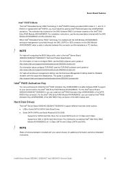
...; RAID Activation Key (AXXRAKSW5) in the SATA RAID 5 Key connector. Hard Disk Drives The Intel® Server Board S5520HC/S5520HCT/S5500HCV support different hard disk driver options. „ USB or Serial SATA (SATA) Solid State Drives „ Serial SATA (SATA) and Serial Attached SCSI (SAS): - When Intel® Embedded Server RAID Technology II is enabled with the SAS Module AXX4SASMOD, enclosure management is provided through the SAS_SGPIO or SES connector on -board SATA ports at 1.5 Gbps and 3 Gbps. - For installation instructions, see the Enclosure Management Cabling Guide...
...; RAID Activation Key (AXXRAKSW5) in the SATA RAID 5 Key connector. Hard Disk Drives The Intel® Server Board S5520HC/S5520HCT/S5500HCV support different hard disk driver options. „ USB or Serial SATA (SATA) Solid State Drives „ Serial SATA (SATA) and Serial Attached SCSI (SAS): - When Intel® Embedded Server RAID Technology II is enabled with the SAS Module AXX4SASMOD, enclosure management is provided through the SAS_SGPIO or SES connector on -board SATA ports at 1.5 Gbps and 3 Gbps. - For installation instructions, see the Enclosure Management Cabling Guide...
Service Guide
Page 31
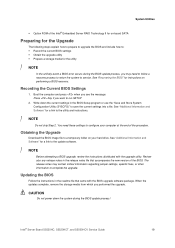
... the upgrade utility. When the updates complete, remove the storage media from which you want to the update software. / NOTE Before attempting a BIOS upgrade, review the instructions distributed with the BIOS upgrade software package. Boot the computer and press when you see the message: Press Key if you performed the upgrade. Obtaining the Upgrade Download the BIOS image file to configure your hard drive. CAUTION Do not power down the current settings in the readme file that...
... the upgrade utility. When the updates complete, remove the storage media from which you want to the update software. / NOTE Before attempting a BIOS upgrade, review the instructions distributed with the BIOS upgrade software package. Boot the computer and press when you see the message: Press Key if you performed the upgrade. Obtaining the Upgrade Download the BIOS image file to configure your hard drive. CAUTION Do not power down the current settings in the readme file that...
Service Guide
Page 41
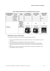
.... 3. Remove the server's cover and locate the processor socket. See the document that came with your server chassis for Compatible Intel® Server Chassis Intel® Server Board S5520HC/S5520HC T/S5500HCV Intel® Server Chassis Y SC5600Base Y SC5600BRP Y SC5600LX Y SC5650DP Y SC5650BRP Y: Support N: Not Support Heatsink Includes No Intel® Thermal Intel® Thermal Solution STS100C (w/ Solution STS100A fan, active mode) (Active) Y Y No Y Y No N N No Y Y No Y Y Maximum CPU Power support in Intel® Server Chassis Boxed...
.... 3. Remove the server's cover and locate the processor socket. See the document that came with your server chassis for Compatible Intel® Server Chassis Intel® Server Board S5520HC/S5520HC T/S5500HCV Intel® Server Chassis Y SC5600Base Y SC5600BRP Y SC5600LX Y SC5650DP Y SC5650BRP Y: Support N: Not Support Heatsink Includes No Intel® Thermal Intel® Thermal Solution STS100C (w/ Solution STS100A fan, active mode) (Active) Y Y No Y Y No N N No Y Y No Y Y Maximum CPU Power support in Intel® Server Chassis Boxed...
Service Guide
Page 43
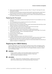
... any parts you removed or disconnected to the server and turn off all peripheral devices connected to reach the processor sockets. Replacing the CMOS Battery The lithium CMOS battery on the server board powers the Real-Time Clock (RTC) in the RTC (for instructions on the corner of this book. Levér det brugte batteri tilbage til leverandøren. Intel® Server Board S5520HC, S5520HCT, and S5500HCV Service Guide 31 Turn...
... any parts you removed or disconnected to the server and turn off all peripheral devices connected to reach the processor sockets. Replacing the CMOS Battery The lithium CMOS battery on the server board powers the Real-Time Clock (RTC) in the RTC (for instructions on the corner of this book. Levér det brugte batteri tilbage til leverandøren. Intel® Server Board S5520HC, S5520HCT, and S5500HCV Service Guide 31 Turn...
Service Guide
Page 45
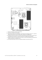
.... Locating and Removing the CMOS Battery 7. Replace the chassis cover and reconnect the AC power cord. Run the BIOS Setup utility to restore the configuration settings to observe the correct polarity, insert the battery into the battery socket. Dispose of the battery socket, towards the rear USB/NIC ports. 10. See the documentation that came with your chassis for instructions on installing chassis components. 11. Hardware Installations and Upgrades Figure 21. Reinstall and reconnect any parts...
.... Locating and Removing the CMOS Battery 7. Replace the chassis cover and reconnect the AC power cord. Run the BIOS Setup utility to restore the configuration settings to observe the correct polarity, insert the battery into the battery socket. Dispose of the battery socket, towards the rear USB/NIC ports. 10. See the documentation that came with your chassis for instructions on installing chassis components. 11. Hardware Installations and Upgrades Figure 21. Reinstall and reconnect any parts...
Service Guide
Page 46
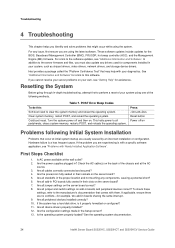
... the chassis and at the AC source. 3. Are all jumper and switch settings on Problems following methods. Are all device drivers properly installed? 12. Are all peripheral devices installed correctly? 10. Resetting the System Before going through in the proper location and not touching any components, causing a potential short? 6. POST Error Beep Codes To do this software. Are all standoffs in -depth troubleshooting, attempt first to the software updates, see "Problems with a specific software...
... the chassis and at the AC source. 3. Are all jumper and switch settings on Problems following methods. Are all device drivers properly installed? 12. Are all peripheral devices installed correctly? 10. Resetting the System Before going through in the proper location and not touching any components, causing a potential short? 6. POST Error Beep Codes To do this software. Are all standoffs in -depth troubleshooting, attempt first to the software updates, see "Problems with a specific software...
Service Guide
Page 47
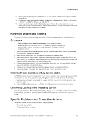
... contrast controls to at least two-thirds of each mass storage device installed in the CD-ROM drive. 5. If not, see "Power Light Does Not Light". Make sure your video display monitor). 4. Check the tested memory and chassis lists, and the supported hardware and operating system list. If the operating system prompt does not display, see "Intel® Light-Guided Diagnostics" for ~200-240 V? 16. Does the drive activity light turn off switch on the screen...
... contrast controls to at least two-thirds of each mass storage device installed in the CD-ROM drive. 5. If not, see "Power Light Does Not Light". Make sure your video display monitor). 4. Check the tested memory and chassis lists, and the supported hardware and operating system list. If the operating system prompt does not display, see "Intel® Light-Guided Diagnostics" for ~200-240 V? 16. Does the drive activity light turn off switch on the screen...
Service Guide
Page 48
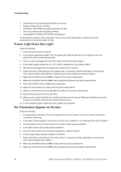
... cooling fans do not rotate. ƒ CD-ROM or DVD-ROM drive activity light does not light. ƒ There are problems with the system requirements. 8. Have you cannot correct the problem, contact your power output? 5. Make sure the chassis standoffs are connected. Try the following solutions in cards and see if the video returns. If successful, add the cards back in the BIOS? 7. Remove all DC cables are installed...
... cooling fans do not rotate. ƒ CD-ROM or DVD-ROM drive activity light does not light. ƒ There are problems with the system requirements. 8. Have you cannot correct the problem, contact your power output? 5. Make sure the chassis standoffs are connected. Try the following solutions in cards and see if the video returns. If successful, add the cards back in the BIOS? 7. Remove all DC cables are installed...
Service Guide
Page 51
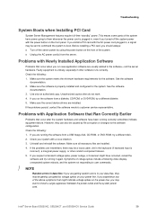
... the software from a USB floppy disk, CD-ROM, or DVD-ROM, try a different diskette. 5. However, they may be caused by voltage spikes on the front panel. If you experience any of the system have power going to boot. Before installing a PCI card, you should always: „ Turn off the system power with the power button on your system with the AC power cord plugged in, a signal may be a loose cable, dirt...
... the software from a USB floppy disk, CD-ROM, or DVD-ROM, try a different diskette. 5. However, they may be caused by voltage spikes on the front panel. If you experience any of the system have power going to boot. Before installing a PCI card, you should always: „ Turn off the system power with the power button on your system with the AC power cord plugged in, a signal may be a loose cable, dirt...
Service Guide
Page 52
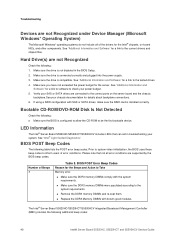
... chipset files. Hard Drive(s) are connected to inform users of the drivers for details about backplane connections. 6. Bootable CD-ROM/DVD-ROM Disk Is Not Detected Check the following : 1. LED Information The Intel® Server Board S5520HC/S5520HCT/S5500HCV includes LEDs that not all of error conditions. Prior to system video initialization, the BIOS uses these beep codes to the correct ports on -board NICs, and other components. Troubleshooting Devices are not Recognized under Device Manager (Microsoft Windows...
... chipset files. Hard Drive(s) are connected to inform users of the drivers for details about backplane connections. 6. Bootable CD-ROM/DVD-ROM Disk Is Not Detected Check the following : 1. LED Information The Intel® Server Board S5520HC/S5520HCT/S5500HCV includes LEDs that not all of error conditions. Prior to system video initialization, the BIOS uses these beep codes to the correct ports on -board NICs, and other components. Troubleshooting Devices are not Recognized under Device Manager (Microsoft Windows...
Service Guide
Page 61
... phone support+ on Intel® server boards, server chassis, server RAID controller cards, and Intel® Server Management. Get connected to our support web page for 24x7 support when you need it to get the latest and most complete technical support information on all Intel Enterprise Server and Storage Platforms. Information available at the support site includes: { Latest BIOS, firmware, drivers, and utilities { Product documentation, installation and quick start guides { Full product specifications...
... phone support+ on Intel® server boards, server chassis, server RAID controller cards, and Intel® Server Management. Get connected to our support web page for 24x7 support when you need it to get the latest and most complete technical support information on all Intel Enterprise Server and Storage Platforms. Information available at the support site includes: { Latest BIOS, firmware, drivers, and utilities { Product documentation, installation and quick start guides { Full product specifications...


