User Guide
Page 5
...activities to identify the source of the Intel® Server Board S5500BC. In this chapter for step-by-step instructions and diagrams for installing or replacing components such as the memory, front panel board, and the battery, among other components...http://support.intel.com/ support/motherboards/server/S5500BC. Chapter 4 provides troubleshooting information. This manual is available in the Technical Product Specification. Chapter 3 provides instructions on using the Intel® Server Board S5500BC. Preface About this chapter, you will find a list of the server board features, ...
...activities to identify the source of the Intel® Server Board S5500BC. In this chapter for step-by-step instructions and diagrams for installing or replacing components such as the memory, front panel board, and the battery, among other components...http://support.intel.com/ support/motherboards/server/S5500BC. Chapter 4 provides troubleshooting information. This manual is available in the Technical Product Specification. Chapter 3 provides instructions on using the Intel® Server Board S5500BC. Preface About this chapter, you will find a list of the server board features, ...
User Guide
Page 6
... Configuration Guide Tested Hardware and Operating System List Reference Chassis List Supported Processors Supported Memory vi Intel® Server Board S5500BC User's Guide For this information or software For in the following accessory items for Intel products, see: http://support.intel.com/support/motherboards/server/S5500BC Additional Information and Software If you need to search "This Category" and then click...
... Configuration Guide Tested Hardware and Operating System List Reference Chassis List Supported Processors Supported Memory vi Intel® Server Board S5500BC User's Guide For this information or software For in the following accessory items for Intel products, see: http://support.intel.com/support/motherboards/server/S5500BC Additional Information and Software If you need to search "This Category" and then click...
User Guide
Page 13
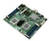
...Card in a Riser Card 21 Figure 17. BIOS Recovery Jumper 29 Figure 19. Diagnostic LED Placement Diagram 51 Intel® Server Board S5500BC User's Guide xiii Configuration Jumper Locations 5 Figure 4. DIMM Configuration Diagram 10 Figure 6. Open the Load Plate ...CMOS Recovery Jumper 31 Figure 21. Installing Memory ...14 Figure 8. Removing the PCI Riser Assembly from the Server System 20 Figure 16. List of Figures Figure 1. Intel® Server Board S5500BC 1 Figure 2. Back Panel Connectors 7 Figure 5. Server Board Connector and Component Locations 3 Figure 3. ...
...Card in a Riser Card 21 Figure 17. BIOS Recovery Jumper 29 Figure 19. Diagnostic LED Placement Diagram 51 Intel® Server Board S5500BC User's Guide xiii Configuration Jumper Locations 5 Figure 4. DIMM Configuration Diagram 10 Figure 6. Open the Load Plate ...CMOS Recovery Jumper 31 Figure 21. Installing Memory ...14 Figure 8. Removing the PCI Riser Assembly from the Server System 20 Figure 16. List of Figures Figure 1. Intel® Server Board S5500BC 1 Figure 2. Back Panel Connectors 7 Figure 5. Server Board Connector and Component Locations 3 Figure 3. ...
User Guide
Page 15
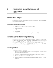
...Hardware...12 Chapter 2: Hardware Installations and Upgrades 13 Before You Begin...13 Tools and Supplies Needed 13 Installing and Removing Memory 13 Installing DIMMs ...13 Removing DIMMs ...14 Installing or Replacing the Processor 15 Installing the Processor 15 Installing the Retention ...Server Utilities 25 Using the BIOS Setup Utility 25 Starting Setup...25 If You Cannot Access Setup 25 Setup Menus ...25 Upgrading the BIOS...27 Preparing for the Upgrade 27 BIOS Recovery Mode and BIOS Flash Update 28 Recovering the BIOS ...28 Clearing the Password...30 Intel® Server Board S5500BC...
...Hardware...12 Chapter 2: Hardware Installations and Upgrades 13 Before You Begin...13 Tools and Supplies Needed 13 Installing and Removing Memory 13 Installing DIMMs ...13 Removing DIMMs ...14 Installing or Replacing the Processor 15 Installing the Processor 15 Installing the Retention ...Server Utilities 25 Using the BIOS Setup Utility 25 Starting Setup...25 If You Cannot Access Setup 25 Setup Menus ...25 Upgrading the BIOS...27 Preparing for the Upgrade 27 BIOS Recovery Mode and BIOS Flash Update 28 Recovering the BIOS ...28 Clearing the Password...30 Intel® Server Board S5500BC...
User Guide
Page 22
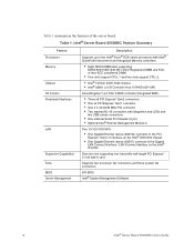
Intel® Server Board S5500BC Feature Summary Feature Processors Memory Chipset I/O Control Peripheral Interfaces LAN Expansion Capabilities Fans BIOS Server Management Description Supports up to two Intel® Xeon® 5500 series processors with Intel® QuickPath Interconnect and Integrated Memory controllers. • Eight DDR3 DIMM slots supporting DDR3 800/1066/1333 MT/s ECC Registered DIMM and ECC or Non...
Intel® Server Board S5500BC Feature Summary Feature Processors Memory Chipset I/O Control Peripheral Interfaces LAN Expansion Capabilities Fans BIOS Server Management Description Supports up to two Intel® Xeon® 5500 series processors with Intel® QuickPath Interconnect and Integrated Memory controllers. • Eight DDR3 DIMM slots supporting DDR3 800/1066/1333 MT/s ECC Registered DIMM and ECC or Non...
User Guide
Page 29
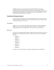
... Information and Software". The minimal population possible is needed, you can install the optional Intel® RAID Activation Key AXXRAKSW5. Memory The Intel® Server Board S5500BC supports a DD3-based memory subsystem. Intel® Server Board S5500BC User's Guide 9 Hardware Requirements To avoid integration difficulties and possible board damage, your system must meet the following requirements outlined. For information on how to...
... Information and Software". The minimal population possible is needed, you can install the optional Intel® RAID Activation Key AXXRAKSW5. Memory The Intel® Server Board S5500BC supports a DD3-based memory subsystem. Intel® Server Board S5500BC User's Guide 9 Hardware Requirements To avoid integration difficulties and possible board damage, your system must meet the following requirements outlined. For information on how to...
User Guide
Page 30
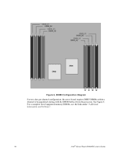
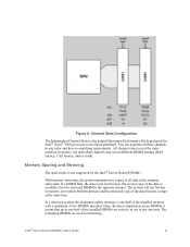
See Figure 6. Figure 5. For a complete list of supported memory DIMMs, see the links under "Additional Information and Software". 10 Intel® Server Board S5500BC User's Guide DIMM Configuration Diagram For two slots per channel configuration, the server board requires DDR3 DIMMs within a channel to be populated starting with the DIMM farthest from the processor.
See Figure 6. Figure 5. For a complete list of supported memory DIMMs, see the links under "Additional Information and Software". 10 Intel® Server Board S5500BC User's Guide DIMM Configuration Diagram For two slots per channel configuration, the server board requires DDR3 DIMMs within a channel to be populated starting with the DIMM farthest from the processor.
User Guide
Page 31
... the primary and the mirrored copy of two DIMMs installed. The remaining DIMMs are actively in any one time. Intel® Server Board S5500BC User's Guide 11 Memory Sparing and Mirroring The spare mode is the default Maximum Performance Mode preferred for mirroring. The system will not fail... due to one -half of the installed memory with a minimum of the data become corrupt at any order and have no matching requirements. Channel Slots Configuration The Independent Channel Mode is not supported by the Intel® Server Board S5500BC. All channels must run at the same ...
... the primary and the mirrored copy of two DIMMs installed. The remaining DIMMs are actively in any one time. Intel® Server Board S5500BC User's Guide 11 Memory Sparing and Mirroring The spare mode is the default Maximum Performance Mode preferred for mirroring. The system will not fail... due to one -half of the installed memory with a minimum of the data become corrupt at any order and have no matching requirements. Channel Slots Configuration The Independent Channel Mode is not supported by the Intel® Server Board S5500BC. All channels must run at the same ...

User Guide
Page 32
... Intel® Server Board S5500BC provides a connector to enable RAID 5, see the instructions provided with an additional network interface. Optional Hardware Intel® RAID Activation Key If RAID 5 is redirected to a managing system; For information on installing the Intel® Remote Management Module 3, see the documentation included with your server chassis for additional information regarding the memory sub...
... Intel® Server Board S5500BC provides a connector to enable RAID 5, see the instructions provided with an additional network interface. Optional Hardware Intel® RAID Activation Key If RAID 5 is redirected to a managing system; For information on installing the Intel® Remote Management Module 3, see the documentation included with your server chassis for additional information regarding the memory sub...
User Guide
Page 33
...Memory The silkscreen on the board. Turn off the server. 3. For two slots per channel is the socket in Figure 7). Observe the safety and ESD precautions at the beginning of this manual. The DIMM farthest from the server. 4. Disconnect the AC power cord from the processor per channel configurations, the server board... requires DDR3 DIMMs within a channel to be populated starting from the inside of the board. DIMM_A1 is blue on the board for more ...
...Memory The silkscreen on the board. Turn off the server. 3. For two slots per channel is the socket in Figure 7). Observe the safety and ESD precautions at the beginning of this manual. The DIMM farthest from the server. 4. Disconnect the AC power cord from the processor per channel configurations, the server board... requires DDR3 DIMMs within a channel to be populated starting from the inside of the board. DIMM_A1 is blue on the board for more ...

User Guide
Page 34
Installing Memory 5. Position the DIMM above the socket. Removing DIMMs To remove a DIMM, follow these steps: 1. Turn off the server. 3. Remove the AC power cord from the socket. 6. Holding the DIMM by the edges, lift it from the socket, and store it from its anti-... turn off all peripheral devices connected to the open position (see letter "D" in an anti-static package. 14 Intel® Server Board S5500BC User's Guide Holding the DIMM by the edges, remove it in Figure 7). When the DIMM is inserted, push down on the top edge of the ...
Installing Memory 5. Position the DIMM above the socket. Removing DIMMs To remove a DIMM, follow these steps: 1. Turn off the server. 3. Remove the AC power cord from the socket. 6. Holding the DIMM by the edges, lift it from the socket, and store it from its anti-... turn off all peripheral devices connected to the open position (see letter "D" in an anti-static package. 14 Intel® Server Board S5500BC User's Guide Holding the DIMM by the edges, remove it in Figure 7). When the DIMM is inserted, push down on the top edge of the ...
User Guide
Page 45
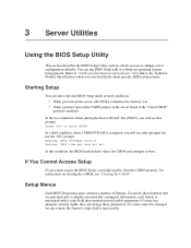
..., the BIOS loads default values for a link to the Technical Product Specification where you might need to clear the CMOS memory. You can change server configuration defaults. Refer to "Additional Information and Software" for CMOS and attempts to change these parameters. Setup Menus Each BIOS... BIOS Setup with a value field that are provided only to the "Clear CMOS" position (enabled). For instructions on the server board to display automatically configured information, each feature is inaccessible. Starting Setup You can find details about specific BIOS setup screens...
..., the BIOS loads default values for a link to the Technical Product Specification where you might need to clear the CMOS memory. You can change server configuration defaults. Refer to "Additional Information and Software" for CMOS and attempts to change these parameters. Setup Menus Each BIOS... BIOS Setup with a value field that are provided only to the "Clear CMOS" position (enabled). For instructions on the server board to display automatically configured information, each feature is inaccessible. Starting Setup You can find details about specific BIOS setup screens...
User Guide
Page 47
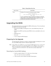
...Intel® Server Board S5500BC User's Guide 27 The code and data in the upgrade file include the following: • On-board system BIOS, including the recovery codes, BIOS Setup Utility, and strings. • On-board video BIOS, and other option ROMs for devices embedded on performing a BIOS recovery. Write down the current settings in flash memory... is exited. Upgrading the BIOS The upgrade utility allows you want to "Recovering the BIOS" for instructions on the server board. • OEM binary area • Microcode • A way to change the BIOS language Preparing for a ...
...Intel® Server Board S5500BC User's Guide 27 The code and data in the upgrade file include the following: • On-board system BIOS, including the recovery codes, BIOS Setup Utility, and strings. • On-board video BIOS, and other option ROMs for devices embedded on performing a BIOS recovery. Write down the current settings in flash memory... is exited. Upgrading the BIOS The upgrade utility allows you want to "Recovering the BIOS" for instructions on the server board. • OEM binary area • Microcode • A way to change the BIOS language Preparing for a ...
User Guide
Page 53
... Troubleshooting This chapter helps you identify and solve problems that may help with your diagnostics. Firmware upgrades include updates for assistance. Intel provides a package called the "Platform Confidence Test" that might occur while using one of the following methods: To do this...system may alternate blinking between amber and green. Resetting the System Before going through in your server problems, refer to clear the system memory and reload the operating system. This clears system memory, restarts POST, reloads the operating system, and halts power to this software. For any...
... Troubleshooting This chapter helps you identify and solve problems that may help with your diagnostics. Firmware upgrades include updates for assistance. Intel provides a package called the "Platform Confidence Test" that might occur while using one of the following methods: To do this...system may alternate blinking between amber and green. Resetting the System Before going through in your server problems, refer to clear the system memory and reload the operating system. This clears system memory, restarts POST, reloads the operating system, and halts power to this software. For any...
User Guide
Page 54
...specific software application, see "Problems with them. Refer to turn on the server (power on add-in Setup correct? • Is the operating system properly loaded? Check the tested memory and chassis lists, as well as the supported hardware and operating system ... device drivers properly installed? • Are the configuration settings made in boards and peripheral devices correct? To check these settings, refer to the tested component lists. 34 Intel® Server Board S5500BC User's Guide Problems Following Initial System Installation Problems that comes with Newly Installed...
...specific software application, see "Problems with them. Refer to turn on the server (power on add-in Setup correct? • Is the operating system properly loaded? Check the tested memory and chassis lists, as well as the supported hardware and operating system ... device drivers properly installed? • Are the configuration settings made in boards and peripheral devices correct? To check these settings, refer to the tested component lists. 34 Intel® Server Board S5500BC User's Guide Problems Following Initial System Installation Problems that comes with Newly Installed...
User Guide
Page 56
... screen. • Characters on the back of the server board and cause a short. 36 Intel® Server Board S5500BC User's Guide If your system has one at a time with a reboot between each addition. • Make sure the memory DIMMs comply with the system requirements. • Make sure the memory DIMMs are populated according to the system requirements. •...
... screen. • Characters on the back of the server board and cause a short. 36 Intel® Server Board S5500BC User's Guide If your system has one at a time with a reboot between each addition. • Make sure the memory DIMMs comply with the system requirements. • Make sure the memory DIMMs are populated according to the system requirements. •...
User Guide
Page 57
... all add-in one at a time with a reboot between each addition. • Make sure the memory DIMMs comply with the system requirements. • Make sure the memory DIMMs are populated according to take effect. 4. Test it switched to the correct system? • Are... : • Is the keyboard functioning? Contact your service representative. 5. Intel® Server Board S5500BC User's Guide 37 Reboot the system for help. Verify the video controller board is fully seated in video controller board, do not display, the video display monitor or video controller may have...
... all add-in one at a time with a reboot between each addition. • Make sure the memory DIMMs comply with the system requirements. • Make sure the memory DIMMs are populated according to take effect. 4. Test it switched to the correct system? • Are... : • Is the keyboard functioning? Contact your service representative. 5. Intel® Server Board S5500BC User's Guide 37 Reboot the system for help. Verify the video controller board is fully seated in video controller board, do not display, the video display monitor or video controller may have...
User Guide
Page 62
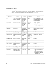
...memory module Display boot 80 POST code Warn on fan failure Identify fan failure Identify processor failure Identify 5 V standby power on state Identify the power state of the system Front panel and board left side DIMM end front of board Left rear of their use. LED Information The Intel® Server Board...Amber Amber Amber Green Notes Press ID LED button or user Server Management software to turn off or S5) • On = Power on or S0) • Slow Blink = Low power state (S1 - S3) 42 Intel® Server Board S5500BC User's Guide LED Name ID System fault Function Aid in ...
...memory module Display boot 80 POST code Warn on fan failure Identify fan failure Identify processor failure Identify 5 V standby power on state Identify the power state of the system Front panel and board left side DIMM end front of board Left rear of their use. LED Information The Intel® Server Board...Amber Amber Amber Green Notes Press ID LED button or user Server Management software to turn off or S5) • On = Power on or S0) • Slow Blink = Low power state (S1 - S3) 42 Intel® Server Board S5500BC User's Guide LED Name ID System fault Function Aid in ...

User Guide
Page 63
...followed by setting the POST Error Pause option as Major, the BIOS enters the error manager and waits for the user to the memory was detected In case of error conditions. If this option by a user-visible code on the BIOS setup Main screen. Prior to... intervention. POST Error Beep Codes Beeps 3 Error Message Memory Error POST Progress code Description System halted because a fatal error related to press an appropriate key before booting the operating system or entering the BIOS Setup. Intel® Server Board S5500BC User's Guide 43 The user can override this option is...
...followed by setting the POST Error Pause option as Major, the BIOS enters the error manager and waits for the user to the memory was detected In case of error conditions. If this option by a user-visible code on the BIOS setup Main screen. Prior to... intervention. POST Error Beep Codes Beeps 3 Error Message Memory Error POST Progress code Description System halted because a fatal error related to press an appropriate key before booting the operating system or entering the BIOS Setup. Intel® Server Board S5500BC User's Guide 43 The user can override this option is...
User Guide
Page 73
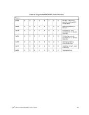
... X 0x24h X 0x25h X 0x26h X 0x27h X 0x28h X Table 8. Diagnostic LED POST Code Decoder X O X X O X X O X X O X X O X X O X X O X X X O X Reading configuration data from memory (SPD on FBDIMM) X X O O Detecting presence of memory X O X X Programming timing parameters in the memory controller X O X O Configuring memory parameters in the memory controller X O O X Optimizing memory controller settings X O O O Initializing memory, such as ECC init O X X X Testing memory Intel® Server Board S5500BC User's Guide 53
... X 0x24h X 0x25h X 0x26h X 0x27h X 0x28h X Table 8. Diagnostic LED POST Code Decoder X O X X O X X O X X O X X O X X O X X O X X X O X Reading configuration data from memory (SPD on FBDIMM) X X O O Detecting presence of memory X O X X Programming timing parameters in the memory controller X O X O Configuring memory parameters in the memory controller X O O X Optimizing memory controller settings X O O O Initializing memory, such as ECC init O X X X Testing memory Intel® Server Board S5500BC User's Guide 53


