User Guide
Page 5
... of this manual, see http://support.intel.com/ support/motherboards/server/S5500BC. Use this chapter for step-by-step instructions and diagrams for installing or replacing components such as the memory, front panel board, and the battery, among other components you identify components and their locations. Chapter 3 provides instructions on the Intel® Server Board S5500BC. Chapter 4 provides troubleshooting information. Information...
... of this manual, see http://support.intel.com/ support/motherboards/server/S5500BC. Use this chapter for step-by-step instructions and diagrams for installing or replacing components such as the memory, front panel board, and the battery, among other components you identify components and their locations. Chapter 3 provides instructions on the Intel® Server Board S5500BC. Chapter 4 provides troubleshooting information. Information...
User Guide
Page 6
... field at : http://support.intel.com/support/motherboards/server/S5500BC/ Unless otherwise indicated in the following table, once on this webpage, type the document or software name in the product box Spares and Configuration Guide Tested Hardware and Operating System List Reference Chassis List Supported Processors Supported Memory vi Intel® Server Board S5500BC User's Guide For this information...
... field at : http://support.intel.com/support/motherboards/server/S5500BC/ Unless otherwise indicated in the following table, once on this webpage, type the document or software name in the product box Spares and Configuration Guide Tested Hardware and Operating System List Reference Chassis List Supported Processors Supported Memory vi Intel® Server Board S5500BC User's Guide For this information...
User Guide
Page 13
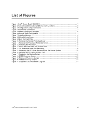
...Installing Memory ...14 Figure 8. Remove the Processor Protective Cover 16 Figure 12. Lifting the Load Lever 15 Figure 9. Replacing the Backup Battery 23 Figure 18. Open the Load Plate 16 Figure 10. BIOS Recovery Jumper 29 Figure 19. Password Recovery Jumper 30 Figure 20. Diagnostic LED Placement Diagram 51 Intel® Server Board S5500BC...1. Back Panel Connectors 7 Figure 5. Intel® Server Board S5500BC 1 Figure 2. Server Board Connector and Component Locations 3 Figure 3. Channel Slots Configuration 11 Figure 7. Installing a PCI Card in a Riser Card...
...Installing Memory ...14 Figure 8. Remove the Processor Protective Cover 16 Figure 12. Lifting the Load Lever 15 Figure 9. Replacing the Backup Battery 23 Figure 18. Open the Load Plate 16 Figure 10. BIOS Recovery Jumper 29 Figure 19. Password Recovery Jumper 30 Figure 20. Diagnostic LED Placement Diagram 51 Intel® Server Board S5500BC...1. Back Panel Connectors 7 Figure 5. Intel® Server Board S5500BC 1 Figure 2. Server Board Connector and Component Locations 3 Figure 3. Channel Slots Configuration 11 Figure 7. Installing a PCI Card in a Riser Card...
User Guide
Page 15
... Chapter 1: Server Board Features 1 Connector and Component Locations 3 Configuration Jumpers...5 Back Panel Connectors ...7 RAID Support...8 Hardware Requirements 9 Optional Hardware...12 Chapter 2: Hardware Installations and Upgrades 13 Before You Begin...13 Tools and Supplies Needed 13 Installing and Removing Memory 13 Installing DIMMs ...13 Removing DIMMs ...14 Installing or Replacing the Processor 15 Installing the Processor 15 Installing the Retention...
... Chapter 1: Server Board Features 1 Connector and Component Locations 3 Configuration Jumpers...5 Back Panel Connectors ...7 RAID Support...8 Hardware Requirements 9 Optional Hardware...12 Chapter 2: Hardware Installations and Upgrades 13 Before You Begin...13 Tools and Supplies Needed 13 Installing and Removing Memory 13 Installing DIMMs ...13 Removing DIMMs ...14 Installing or Replacing the Processor 15 Installing the Processor 15 Installing the Retention...
User Guide
Page 29
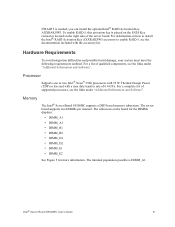
... can install the optional Intel® RAID Activation Key AXXRAKSW5. If RAID 5 is DIMM_A1. For a list of qualified components, see the links under "Additional Information and Software". For a complete list of supported processors, see the documentation included with a max data transfer rate of the server board. Memory The Intel® Server Board S5500BC supports a DD3-based memory subsystem. Intel® Server Board S5500BC User...
... can install the optional Intel® RAID Activation Key AXXRAKSW5. If RAID 5 is DIMM_A1. For a list of qualified components, see the links under "Additional Information and Software". For a complete list of supported processors, see the documentation included with a max data transfer rate of the server board. Memory The Intel® Server Board S5500BC supports a DD3-based memory subsystem. Intel® Server Board S5500BC User...
User Guide
Page 31
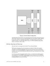
... the second copy of the data is duplicated across DIMMs, it means that up to memory error unless both the primary and the mirrored copy of all three channels in any one -half of two DIMMs installed. Intel® Server Board S5500BC User's Guide 11 All channels must run at the same interface frequency, but individual...
... the second copy of the data is duplicated across DIMMs, it means that up to memory error unless both the primary and the mirrored copy of all three channels in any one -half of two DIMMs installed. Intel® Server Board S5500BC User's Guide 11 All channels must run at the same interface frequency, but individual...

User Guide
Page 32
... included with your server chassis for additional information regarding the memory sub-system. Your supply must provide a minimum of 3.5 A of the server board. The RMM3 card provides the Integrated BMC with the module. 12 Intel® Server Board S5500BC User's Guide For installation instructions on the right side of the server. Intel® Remote Management Module 3 The Intel® Server Board S5500BC provides a connector to...
... included with your server chassis for additional information regarding the memory sub-system. Your supply must provide a minimum of 3.5 A of the server board. The RMM3 card provides the Integrated BMC with the module. 12 Intel® Server Board S5500BC User's Guide For installation instructions on the right side of the server. Intel® Remote Management Module 3 The Intel® Server Board S5500BC provides a connector to...
User Guide
Page 33
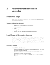
... nosed pliers • A ruler • Pen or pencil • Antistatic wrist strap and conductive foam pad (recommended) Installing and Removing Memory The silkscreen on the board. DIMM_A1 is blue on the board for more information. 2. Remove the server's cover and locate the DIMM sockets (see letter "A" to "E" in blue closest to be populated starting from...
... nosed pliers • A ruler • Pen or pencil • Antistatic wrist strap and conductive foam pad (recommended) Installing and Removing Memory The silkscreen on the board. DIMM_A1 is blue on the board for more information. 2. Remove the server's cover and locate the DIMM sockets (see letter "A" to "E" in blue closest to be populated starting from...

User Guide
Page 34
...Figure 7). 9. When the DIMM is inserted, push down on the top edge of the DIMM into place (see letter "C" in Figure 7). Replace the server's cover and reconnect the AC power cord. Removing DIMMs To remove a DIMM, follow these steps: 1. See "Safety Information" for more information. 2.... socket. Figure 7. Installing Memory 5. Make sure the clips are pushed outward to the server and turn off the server. 3. Make sure the clips at each end of the DIMM socket(s) are firmly in place (see letter "B" in an anti-static package. 14 Intel® Server Board S5500BC User's Guide Holding ...
...Figure 7). 9. When the DIMM is inserted, push down on the top edge of the DIMM into place (see letter "C" in Figure 7). Replace the server's cover and reconnect the AC power cord. Removing DIMMs To remove a DIMM, follow these steps: 1. See "Safety Information" for more information. 2.... socket. Figure 7. Installing Memory 5. Make sure the clips are pushed outward to the server and turn off the server. 3. Make sure the clips at each end of the DIMM socket(s) are firmly in place (see letter "B" in an anti-static package. 14 Intel® Server Board S5500BC User's Guide Holding ...
User Guide
Page 53
...Cold boot reset. Press: Reset button Power off and then on Intel provides a package called the "Platform Confidence Test" that might occur while using one of the following methods: To do this time. Clear system memory, restart POST, and reload the operating system. Firmware upgrades include ... (HSC). This may appear hang. When the quiet time completes, the status LED will indicate activity. In addition to the server firmware and files, you installed in -depth troubleshooting, first attempt to solid green. The POST LEDs will change to reset your system, such as 40 seconds...
...Cold boot reset. Press: Reset button Power off and then on Intel provides a package called the "Platform Confidence Test" that might occur while using one of the following methods: To do this time. Clear system memory, restart POST, and reload the operating system. Firmware upgrades include ... (HSC). This may appear hang. When the quiet time completes, the status LED will indicate activity. In addition to the server firmware and files, you installed in -depth troubleshooting, first attempt to solid green. The POST LEDs will change to reset your system, such as 40 seconds...
User Guide
Page 54
... disk drive, is a less frequent cause. Check the tested memory and chassis lists, as well as the supported hardware and operating system list. Problems Following Initial System Installation Problems that comes with Newly Installed Application Software". Check the AC cable(s) on the back of the... settings on light should be lit)? • Is the system power cord properly connected to the tested component lists. 34 Intel® Server Board S5500BC User's Guide Refer to the manufacturer's documentation that occur at the wall outlet? • Are the power supplies plugged in...
... disk drive, is a less frequent cause. Check the tested memory and chassis lists, as well as the supported hardware and operating system list. Problems Following Initial System Installation Problems that comes with Newly Installed Application Software". Check the AC cable(s) on the back of the... settings on light should be lit)? • Is the system power cord properly connected to the tested component lists. 34 Intel® Server Board S5500BC User's Guide Refer to the manufacturer's documentation that occur at the wall outlet? • Are the power supplies plugged in...
User Guide
Page 56
...in one , is not detected. If so, the power LED might be defective or the cable from the front panel to the server board might be loose. • Have you cannot correct the problem, contact your service representative or authorized dealer for these specific problems: &#...Make sure the memory DIMMs are installed only below mounting holes. If you securely plugged the server AC power cord into the same power outlet function correctly? • Some ATX power supplies have a power switch on the back of the server board and cause a short. 36 Intel® Server Board S5500BC User's Guide ...
...in one , is not detected. If so, the power LED might be defective or the cable from the front panel to the server board might be loose. • Have you cannot correct the problem, contact your service representative or authorized dealer for these specific problems: &#...Make sure the memory DIMMs are installed only below mounting holes. If you securely plugged the server AC power cord into the same power outlet function correctly? • Some ATX power supplies have a power switch on the back of the server board and cause a short. 36 Intel® Server Board S5500BC User's Guide ...
User Guide
Page 57
...are populated according to the system requirements. • Remove the memory DIMMs and re-seat them . If successful, add the cards back in the server board connector. 3. This information is fully seated in one at a...installed? • Does this video monitor work correctly if plugged into a different system? Reboot the system for help. If you use a switch box, is functioning. • Is the video monitor plugged in and turned on? Contact your service representative. 5. Verify the video works using the onboard video controller. 2. Intel® Server Board S5500BC...
...are populated according to the system requirements. • Remove the memory DIMMs and re-seat them . If successful, add the cards back in the server board connector. 3. This information is fully seated in one at a...installed? • Does this video monitor work correctly if plugged into a different system? Reboot the system for help. If you use a switch box, is functioning. • Is the video monitor plugged in and turned on? Contact your service representative. 5. Verify the video works using the onboard video controller. 2. Intel® Server Board S5500BC...

User Guide
Page 77
... been called) Pre-EFI Initialization Module (PEIM) / Recovery 0x30h X X O O X X X X Crisis recovery has been initiated because of a user request Intel® Server Board S5500BC User's Guide 57 Diagnostic LED POST Code Decoder 0xE2h O O O X X X O X Initial memory found, configured, and installed correctly 0xE3h O O O X X X O O Reserved for initialization module use (PEIM) Driver Execution Environment (DXE) Core (not accompanied by a beep code...
... been called) Pre-EFI Initialization Module (PEIM) / Recovery 0x30h X X O O X X X X Crisis recovery has been initiated because of a user request Intel® Server Board S5500BC User's Guide 57 Diagnostic LED POST Code Decoder 0xE2h O O O X X X O X Initial memory found, configured, and installed correctly 0xE3h O O O X X X O O Reserved for initialization module use (PEIM) Driver Execution Environment (DXE) Core (not accompanied by a beep code...

User Guide
Page 79
...technical phone support+ on Intel® server boards, server chassis, server RAID controller cards, and Intel® Server Management: http://www.intel.com/reseller/ Warranty Information Connect to Intel's website to obtain warranty information: http://support.intel.com/ support/motherboards/server/sb/CS-010807.htm... Product documentation, installation and quick start guides • Full product specifications, technical advisories, and errata • Compatibility documentation for memory, hardware add-in cards, chassis support matrix, and operating systems • Server and chassis accessory...
...technical phone support+ on Intel® server boards, server chassis, server RAID controller cards, and Intel® Server Management: http://www.intel.com/reseller/ Warranty Information Connect to Intel's website to obtain warranty information: http://support.intel.com/ support/motherboards/server/sb/CS-010807.htm... Product documentation, installation and quick start guides • Full product specifications, technical advisories, and errata • Compatibility documentation for memory, hardware add-in cards, chassis support matrix, and operating systems • Server and chassis accessory...
Quick Start Guide
Page 1
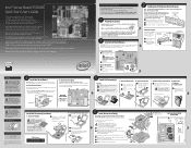
... diagonally, according to install the server board, make server board connections or install other components. 3 Install Server Board Bumpers IMPORTANT NOTE: If you are using an Intel® Server Chassis, use with compatible heat sink. • Memory Type: Minimum of ...-Intel server chassis, see the Intel® Server Board and Server Chassis Safety Information document at http://support.intel.com/motherboards/server/s5500BC. Intel® Server Chassis SC5650 Shown I /O shield Shield installs from each of the processor has components that came with your server board. Install ...
... diagonally, according to install the server board, make server board connections or install other components. 3 Install Server Board Bumpers IMPORTANT NOTE: If you are using an Intel® Server Chassis, use with compatible heat sink. • Memory Type: Minimum of ...-Intel server chassis, see the Intel® Server Board and Server Chassis Safety Information document at http://support.intel.com/motherboards/server/s5500BC. Intel® Server Chassis SC5650 Shown I /O shield Shield installs from each of the processor has components that came with your server board. Install ...


