User Guide
Page 2
... of the system integrator that need adequate airflow for use in connection with Intel® products. Intel may be held responsible if components fail or the server board does not operate correctly when used together. All Rights Reserved ii Intel® Server Board S5500BC User's Guide Intel's own chassis are not designed, intended or authorized for cooling. Disclaimer Information...
... of the system integrator that need adequate airflow for use in connection with Intel® products. Intel may be held responsible if components fail or the server board does not operate correctly when used together. All Rights Reserved ii Intel® Server Board S5500BC User's Guide Intel's own chassis are not designed, intended or authorized for cooling. Disclaimer Information...
User Guide
Page 5
... source of the product, and product diagrams to update the system. Use this manual, see http://support.intel.com/ support/motherboards/server/S5500BC. This document provides a brief overview of the features of the board/chassis, a list of the Intel® Server Board S5500BC. Manual Organization Chapter 1 provides a brief overview of accessories or other components. Chapter 3 provides instructions on how...
... source of the product, and product diagrams to update the system. Use this manual, see http://support.intel.com/ support/motherboards/server/S5500BC. This document provides a brief overview of the features of the board/chassis, a list of the Intel® Server Board S5500BC. Manual Organization Chapter 1 provides a brief overview of accessories or other components. Chapter 3 provides instructions on how...
User Guide
Page 6
... with this product Processors tested with this product DIMMs tested with this Document or Software Technical Product Specification Intel® Server Board S5500BC Quick Start User's Guide in the search field at : http://support.intel.com/support/motherboards/server/S5500BC/ Unless otherwise indicated in the following table, once on this webpage, type the document or software name in...
... with this product Processors tested with this product DIMMs tested with this Document or Software Technical Product Specification Intel® Server Board S5500BC Quick Start User's Guide in the search field at : http://support.intel.com/support/motherboards/server/S5500BC/ Unless otherwise indicated in the following table, once on this webpage, type the document or software name in...
User Guide
Page 7
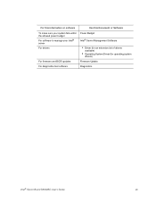
For this information or software To make sure your system falls within the allowed power budget For software to manage your Intel® server For drivers For firmware and BIOS updates For diagnostics test software Use this Document or Software Power Budget Intel® Server Management Software • Driver (for an extensive list of drivers available) • Operating System Driver (for operating system drivers) Firmware Update Diagnostics Intel® Server Board S5500BC User's Guide vii
For this information or software To make sure your system falls within the allowed power budget For software to manage your Intel® server For drivers For firmware and BIOS updates For diagnostics test software Use this Document or Software Power Budget Intel® Server Management Software • Driver (for an extensive list of drivers available) • Operating System Driver (for operating system drivers) Firmware Update Diagnostics Intel® Server Board S5500BC User's Guide vii

User Guide
Page 9
... in this document before performing any of the instructions. See also Intel Server Boards and Server Chassis Safety Information on the Intel® Server Deployment Toolkit 3.0 CD and/or at http://support.intel.com/support/ motherboards/server/sb/cs-010770.htm. Consultez Intel Server Boards and Server Chassis Safety Information sur le Intel® Server Deployment Toolkit 3.0 CD ou bien rendez-vous sur le site...
... in this document before performing any of the instructions. See also Intel Server Boards and Server Chassis Safety Information on the Intel® Server Deployment Toolkit 3.0 CD and/or at http://support.intel.com/support/ motherboards/server/sb/cs-010770.htm. Consultez Intel Server Boards and Server Chassis Safety Information sur le Intel® Server Deployment Toolkit 3.0 CD ou bien rendez-vous sur le site...
User Guide
Page 13
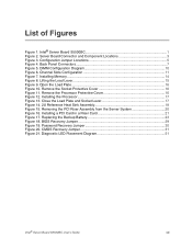
... Figure 11. Lifting the Load Lever 15 Figure 9. Diagnostic LED Placement Diagram 51 Intel® Server Board S5500BC User's Guide xiii Removing the PCI Riser Assembly from the Server System 20 Figure 16. DIMM Configuration Diagram 10 Figure 6. List of Figures Figure 1. Intel® Server Board S5500BC 1 Figure 2. Close the Load Plate and Socket Lever 17 Figure 14. 2U...
... Figure 11. Lifting the Load Lever 15 Figure 9. Diagnostic LED Placement Diagram 51 Intel® Server Board S5500BC User's Guide xiii Removing the PCI Riser Assembly from the Server System 20 Figure 16. DIMM Configuration Diagram 10 Figure 6. List of Figures Figure 1. Intel® Server Board S5500BC 1 Figure 2. Close the Load Plate and Socket Lever 17 Figure 14. 2U...
User Guide
Page 15
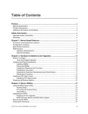
... ...vi Additional Information and Software vi Safety Information ...v Important Safety Instructions ix Warnings...xi Chapter 1: Server Board Features 1 Connector and Component Locations 3 Configuration Jumpers...5 Back Panel Connectors ...7 RAID Support...8 Hardware Requirements...Server Utilities 25 Using the BIOS Setup Utility 25 Starting Setup...25 If You Cannot Access Setup 25 Setup Menus ...25 Upgrading the BIOS...27 Preparing for the Upgrade 27 BIOS Recovery Mode and BIOS Flash Update 28 Recovering the BIOS ...28 Clearing the Password...30 Intel® Server Board S5500BC...
... ...vi Additional Information and Software vi Safety Information ...v Important Safety Instructions ix Warnings...xi Chapter 1: Server Board Features 1 Connector and Component Locations 3 Configuration Jumpers...5 Back Panel Connectors ...7 RAID Support...8 Hardware Requirements...Server Utilities 25 Using the BIOS Setup Utility 25 Starting Setup...25 If You Cannot Access Setup 25 Setup Menus ...25 Upgrading the BIOS...27 Preparing for the Upgrade 27 BIOS Recovery Mode and BIOS Flash Update 28 Recovering the BIOS ...28 Clearing the Password...30 Intel® Server Board S5500BC...
User Guide
Page 16
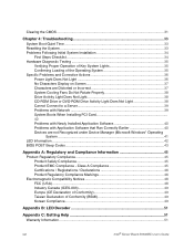
... Properly 38 Drive Activity Light Does Not Light 38 CD-ROM Drive or DVD-ROM Drive Activity Light Does Not Light 38 Cannot Connect to a Server 39 Problems with Network 39 System Boots When Installing PCI Card 40 Problems with Newly Installed Application Software 40 Problems with Application Software that Ran... Key System Lights 35 Confirming Loading of Conformity (BSMI 49 Korean Compliance...49 Appendix B: LED Decoder 51 Appendix C: Getting Help 51 Warranty Information...51 xvi Intel® Server Board S5500BC User's Guide
... Properly 38 Drive Activity Light Does Not Light 38 CD-ROM Drive or DVD-ROM Drive Activity Light Does Not Light 38 Cannot Connect to a Server 39 Problems with Network 39 System Boots When Installing PCI Card 40 Problems with Newly Installed Application Software 40 Problems with Application Software that Ran... Key System Lights 35 Confirming Loading of Conformity (BSMI 49 Korean Compliance...49 Appendix B: LED Decoder 51 Appendix C: Getting Help 51 Warranty Information...51 xvi Intel® Server Board S5500BC User's Guide
User Guide
Page 19
Diagnostic LED Placement Diagram 51 Table 7. List of Tables Table 1. POST Progress Code LED Example 52 Table 8. POST Error Beep Codes 43 Table 6. Diagnostic LED POST Code Decoder 52 Intel® Server Board S5500BC User's Guide xix Setup Menu Key Use 26 Table 5. Intel® Server Board S5500BC Feature Summary 2 Table 2. Configuration Jumper [J4A1 5 Table 3. NIC LEDs ...8 Table 4.
Diagnostic LED Placement Diagram 51 Table 7. List of Tables Table 1. POST Progress Code LED Example 52 Table 8. POST Error Beep Codes 43 Table 6. Diagnostic LED POST Code Decoder 52 Intel® Server Board S5500BC User's Guide xix Setup Menu Key Use 26 Table 5. Intel® Server Board S5500BC Feature Summary 2 Table 2. Configuration Jumper [J4A1 5 Table 3. NIC LEDs ...8 Table 4.

User Guide
Page 21
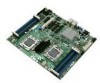
Figure 1. 1 Server Board Features This chapter briefly describes the main features of important components and connections on the server system. Intel® Server Board S5500BC This chapter provides illustrations of the product, a list of the server board features, and diagrams showing the location of the Intel® Server Board S5500BC.
Figure 1. 1 Server Board Features This chapter briefly describes the main features of important components and connections on the server system. Intel® Server Board S5500BC This chapter provides illustrations of the product, a list of the server board features, and diagrams showing the location of the Intel® Server Board S5500BC.
User Guide
Page 22
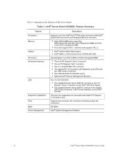
Table 1 summarizes the features of the server board. Table 1. Supports two processor fan connectors and three system fan connectors EFI BIOS Intel® System Management Software 2 Intel® Server Board S5500BC User's Guide One riser slot supporting one low-profile half-length PCI Express* 2.0 x8 add-in card. Intel® Server Board S5500BC Feature Summary Feature Processors Memory Chipset I/O Control Peripheral Interfaces...
Table 1 summarizes the features of the server board. Table 1. Supports two processor fan connectors and three system fan connectors EFI BIOS Intel® System Management Software 2 Intel® Server Board S5500BC User's Guide One riser slot supporting one low-profile half-length PCI Express* 2.0 x8 add-in card. Intel® Server Board S5500BC Feature Summary Feature Processors Memory Chipset I/O Control Peripheral Interfaces...
User Guide
Page 23
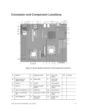
... Serial B header Y. SATA 5 D. Slot 4, 32-bit/33 MHz PCI G. Intel® RMM3 slot Q. SATA 3 L. Internal dual port USB2.0 header M. CPU Socket 1 Z. Slot 3, PCI Express* x4 P. System fan 3 header BB. System Fan 1 header HH. CPU Power Connector C. Intel® IOH 5500 chipset E. SATA 2 Intel® Server Board S5500BC User's Guide 3 SATA Key AA. Server Board Connector and Component Locations A.
... Serial B header Y. SATA 5 D. Slot 4, 32-bit/33 MHz PCI G. Intel® RMM3 slot Q. SATA 3 L. Internal dual port USB2.0 header M. CPU Socket 1 Z. Slot 3, PCI Express* x4 P. System fan 3 header BB. System Fan 1 header HH. CPU Power Connector C. Intel® IOH 5500 chipset E. SATA 2 Intel® Server Board S5500BC User's Guide 3 SATA Key AA. Server Board Connector and Component Locations A.

User Guide
Page 25
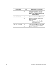
... have a jumper in place for normal system operation. (Default) 5 Configuration Jumper [J4A1] Jumper Name Pins J8C1: BMC Force Update 1-2 2-3 J2D1: Password Clear 1-2 2-3 J2D2: CMOS Clear 1-2 Intel® Server Board S5500BC User's Guide What happens at system reset... Configuration Jumper Location Table 2.
... have a jumper in place for normal system operation. (Default) 5 Configuration Jumper [J4A1] Jumper Name Pins J8C1: BMC Force Update 1-2 2-3 J2D1: Password Clear 1-2 2-3 J2D2: CMOS Clear 1-2 Intel® Server Board S5500BC User's Guide What happens at system reset... Configuration Jumper Location Table 2.
User Guide
Page 26
... will not boot with a recovery BIOS image. NOTE: These pins should have a jumper in place for normal system operation. (Default) ME force update model. 6 Intel® Server Board S5500BC User's Guide These pins should have a jumper in place for normal operation. These pins should not be jumpered for normal system operation.(Default) The main...
... will not boot with a recovery BIOS image. NOTE: These pins should have a jumper in place for normal system operation. (Default) ME force update model. 6 Intel® Server Board S5500BC User's Guide These pins should have a jumper in place for normal operation. These pins should not be jumpered for normal system operation.(Default) The main...
User Guide
Page 27
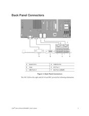
Back Panel Connectors A. Video C. Intel® Server Board S5500BC User's Guide 7 USB Port 6-7 D. NIC Port 1 F. Back Panel Connectors The NIC LEDs at the right and left of each NIC provide the following information. USB Port 8-9 E. NIC Port 2 (MGMT) Figure 4. Serial Port A B.
Back Panel Connectors A. Video C. Intel® Server Board S5500BC User's Guide 7 USB Port 6-7 D. NIC Port 1 F. Back Panel Connectors The NIC LEDs at the right and left of each NIC provide the following information. USB Port 8-9 E. NIC Port 2 (MGMT) Figure 4. Serial Port A B.
User Guide
Page 28
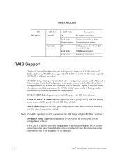
When this connector on the server board and to the backplane or I2C interface. 8 Intel® Server Board S5500BC User's Guide Note: For AHCI capability in place Transmit/receive activity 10 Mbps connection (if left LED is enabled, you must set the "... utility provides multiple drive configuration options on or blinking) 100 Mbps connection 1000 Mbps connection RAID Support The Intel® Server Board provides six SATA ports (3 Gbps) via ICH10R with Intel® Embedded Server RAID Technology, with activation key. NIC LEDs NIC NIC1/NIC2 LED Color Left LED Right LED LED State...
When this connector on the server board and to the backplane or I2C interface. 8 Intel® Server Board S5500BC User's Guide Note: For AHCI capability in place Transmit/receive activity 10 Mbps connection (if left LED is enabled, you must set the "... utility provides multiple drive configuration options on or blinking) 100 Mbps connection 1000 Mbps connection RAID Support The Intel® Server Board provides six SATA ports (3 Gbps) via ICH10R with Intel® Embedded Server RAID Technology, with activation key. NIC LEDs NIC NIC1/NIC2 LED Color Left LED Right LED LED State...
User Guide
Page 29
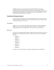
... outlined. For a list of qualified components, see the links under "Additional Information and Software". The server board supports two DIMMs per channel. Memory The Intel® Server Board S5500BC supports a DD3-based memory subsystem. The silkscreen on how to install the Intel® RAID Activation Key AXXRAKSW5 accessory to enable RAID 5, see the links under "Additional Information...
... outlined. For a list of qualified components, see the links under "Additional Information and Software". The server board supports two DIMMs per channel. Memory The Intel® Server Board S5500BC supports a DD3-based memory subsystem. The silkscreen on how to install the Intel® RAID Activation Key AXXRAKSW5 accessory to enable RAID 5, see the links under "Additional Information...
User Guide
Page 30
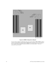
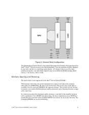
Figure 5. For a complete list of supported memory DIMMs, see the links under "Additional Information and Software". 10 Intel® Server Board S5500BC User's Guide DIMM Configuration Diagram For two slots per channel configuration, the server board requires DDR3 DIMMs within a channel to be populated starting with the DIMM farthest from the processor. See Figure 6.
Figure 5. For a complete list of supported memory DIMMs, see the links under "Additional Information and Software". 10 Intel® Server Board S5500BC User's Guide DIMM Configuration Diagram For two slots per channel configuration, the server board requires DDR3 DIMMs within a channel to be populated starting with the DIMM farthest from the processor. See Figure 6.
User Guide
Page 31
In a mirrored system, the maximum usable memory is one time. Intel® Server Board S5500BC User's Guide 11 If a DIMM fails, the data is not lost because the second copy of two DIMMs installed. Since the data is the default ... platforms. You can populate all data in any one -half of the installed memory with a minimum of the data is not supported by the Intel® Server Board S5500BC. With memory mirroring, the system maintains two copies of the data become corrupt at the same time. Channel Slots Configuration The Independent Channel Mode is...
In a mirrored system, the maximum usable memory is one time. Intel® Server Board S5500BC User's Guide 11 If a DIMM fails, the data is not lost because the second copy of two DIMMs installed. Since the data is the default ... platforms. You can populate all data in any one -half of the installed memory with a minimum of the data is not supported by the Intel® Server Board S5500BC. With memory mirroring, the system maintains two copies of the data become corrupt at the same time. Channel Slots Configuration The Independent Channel Mode is...

User Guide
Page 32
... control of 5 V standby current or the board will not boot. Intel® Remote Management Module 3 The Intel® Server Board S5500BC provides a connector to view and operate the server remotely in real time. See the Intel® Server Board S5500BC Technical Product Specification for additional drive information and ...if it was installed on the right side of the server board. Your supply must provide a minimum of 3.5 A of the server. See the documentation included with the module. 12 Intel® Server Board S5500BC User's Guide this activation key is required. USB media...
... control of 5 V standby current or the board will not boot. Intel® Remote Management Module 3 The Intel® Server Board S5500BC provides a connector to view and operate the server remotely in real time. See the Intel® Server Board S5500BC Technical Product Specification for additional drive information and ...if it was installed on the right side of the server board. Your supply must provide a minimum of 3.5 A of the server. See the documentation included with the module. 12 Intel® Server Board S5500BC User's Guide this activation key is required. USB media...


