User Guide
Page 5
... specific BIOS settings and screens is written for system technicians responsible for installing or replacing components such as the memory, front panel board, and the battery, among other components you may need, troubleshooting information, and instructions on how to add and replace components on the Intel® Server Board S5500BC. This manual is available in the Technical Product Specification. Use this chapter for step-by-step instructions and diagrams for troubleshooting, upgrading, and repairing this server board...
... specific BIOS settings and screens is written for system technicians responsible for installing or replacing components such as the memory, front panel board, and the battery, among other components you may need, troubleshooting information, and instructions on how to add and replace components on the Intel® Server Board S5500BC. This manual is available in the Technical Product Specification. Use this chapter for step-by-step instructions and diagrams for troubleshooting, upgrading, and repairing this server board...
User Guide
Page 6
...Product Specification Intel® Server Board S5500BC Quick Start User's Guide in the search field at : http://support.intel.com/support/motherboards/server/S5500BC/ Unless otherwise indicated in the following table, once on this webpage, type the document or software name in the product box Spares and Configuration Guide Tested Hardware and Operating System List Reference Chassis List Supported Processors Supported Memory vi Intel® Server Board S5500BC User's Guide Product Accessories This server board is compatible with the following Intel® Server Chassis: • Intel...
...Product Specification Intel® Server Board S5500BC Quick Start User's Guide in the search field at : http://support.intel.com/support/motherboards/server/S5500BC/ Unless otherwise indicated in the following table, once on this webpage, type the document or software name in the product box Spares and Configuration Guide Tested Hardware and Operating System List Reference Chassis List Supported Processors Supported Memory vi Intel® Server Board S5500BC User's Guide Product Accessories This server board is compatible with the following Intel® Server Chassis: • Intel...
User Guide
Page 7
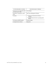
For this information or software To make sure your system falls within the allowed power budget For software to manage your Intel® server For drivers For firmware and BIOS updates For diagnostics test software Use this Document or Software Power Budget Intel® Server Management Software • Driver (for an extensive list of drivers available) • Operating System Driver (for operating system drivers) Firmware Update Diagnostics Intel® Server Board S5500BC User's Guide vii
For this information or software To make sure your system falls within the allowed power budget For software to manage your Intel® server For drivers For firmware and BIOS updates For diagnostics test software Use this Document or Software Power Budget Intel® Server Management Software • Driver (for an extensive list of drivers available) • Operating System Driver (for operating system drivers) Firmware Update Diagnostics Intel® Server Board S5500BC User's Guide vii
User Guide
Page 13
... Locations 3 Figure 3. Remove the Socket Protective Cover 16 Figure 11. Installing the Processor 17 Figure 13. Back Panel Connectors 7 Figure 5. DIMM Configuration Diagram 10 Figure 6. Open the Load Plate 16 Figure 10. Removing the PCI Riser Assembly from the Server System 20 Figure 16. Password Recovery Jumper 30 Figure 20. Diagnostic LED Placement Diagram 51 Intel® Server Board S5500BC User's Guide xiii Remove the Processor Protective Cover 16 Figure 12. BIOS Recovery Jumper 29 Figure 19. Intel® Server Board S5500BC 1 Figure 2. List...
... Locations 3 Figure 3. Remove the Socket Protective Cover 16 Figure 11. Installing the Processor 17 Figure 13. Back Panel Connectors 7 Figure 5. DIMM Configuration Diagram 10 Figure 6. Open the Load Plate 16 Figure 10. Removing the PCI Riser Assembly from the Server System 20 Figure 16. Password Recovery Jumper 30 Figure 20. Diagnostic LED Placement Diagram 51 Intel® Server Board S5500BC User's Guide xiii Remove the Processor Protective Cover 16 Figure 12. BIOS Recovery Jumper 29 Figure 19. Intel® Server Board S5500BC 1 Figure 2. List...
User Guide
Page 15
... ...14 Installing or Replacing the Processor 15 Installing the Processor 15 Installing the Retention Mechanism(s) and Heat Sink(s 17 Replacing a Processor 18 Installing a PCI Add-In Card 20 Installing a PCI Add-In Card 20 Replacing the Backup Battery 22 Chapter 3: Server Utilities 25 Using the BIOS Setup Utility 25 Starting Setup...25 If You Cannot Access Setup 25 Setup Menus ...25 Upgrading the BIOS...27 Preparing for the Upgrade 27 BIOS Recovery Mode and BIOS Flash Update 28 Recovering the BIOS ...28 Clearing the Password...30 Intel® Server Board S5500BC User's Guide xv
... ...14 Installing or Replacing the Processor 15 Installing the Processor 15 Installing the Retention Mechanism(s) and Heat Sink(s 17 Replacing a Processor 18 Installing a PCI Add-In Card 20 Installing a PCI Add-In Card 20 Replacing the Backup Battery 22 Chapter 3: Server Utilities 25 Using the BIOS Setup Utility 25 Starting Setup...25 If You Cannot Access Setup 25 Setup Menus ...25 Upgrading the BIOS...27 Preparing for the Upgrade 27 BIOS Recovery Mode and BIOS Flash Update 28 Recovering the BIOS ...28 Clearing the Password...30 Intel® Server Board S5500BC User's Guide xv
User Guide
Page 16
... 37 System Cooling Fans Do Not Rotate Properly 38 Drive Activity Light Does Not Light 38 CD-ROM Drive or DVD-ROM Drive Activity Light Does Not Light 38 Cannot Connect to a Server 39 Problems with Network 39 System Boots When Installing PCI Card 40 Problems with Newly Installed Application Software 40 Problems with Application Software that Ran Correctly Earlier 40 Devices are not Recognized under Device Manager (Microsoft Windows* Operating System ...41 LED Information ...42 BIOS POST Beep Codes ...43 Appendix...
... 37 System Cooling Fans Do Not Rotate Properly 38 Drive Activity Light Does Not Light 38 CD-ROM Drive or DVD-ROM Drive Activity Light Does Not Light 38 Cannot Connect to a Server 39 Problems with Network 39 System Boots When Installing PCI Card 40 Problems with Newly Installed Application Software 40 Problems with Application Software that Ran Correctly Earlier 40 Devices are not Recognized under Device Manager (Microsoft Windows* Operating System ...41 LED Information ...42 BIOS POST Beep Codes ...43 Appendix...

User Guide
Page 21
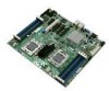
This chapter provides illustrations of the product, a list of the server board features, and diagrams showing the location of the Intel® Server Board S5500BC. 1 Server Board Features This chapter briefly describes the main features of important components and connections on the server system. Figure 1. Intel® Server Board S5500BC
This chapter provides illustrations of the product, a list of the server board features, and diagrams showing the location of the Intel® Server Board S5500BC. 1 Server Board Features This chapter briefly describes the main features of important components and connections on the server system. Figure 1. Intel® Server Board S5500BC
User Guide
Page 22
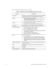
... external Serial Port Header (9 pin) • Optional Intel® Remote Management Module 3 Two 10/100/1000 NICs • One Gigabit Ethernet device (82574L) connects to the PCI Express* Gen2 x1 interface on the Intel® IOH 5500 chipset. • One Gigabit Ethernet device (82567) connects to the Gigabit LAN Connect Interface / LAN Connect Interface on the Intel® ICH10R. Supports two processor fan connectors and three system fan connectors EFI BIOS Intel® System Management Software 2 Intel® Server Board S5500BC User's Guide Table...
... external Serial Port Header (9 pin) • Optional Intel® Remote Management Module 3 Two 10/100/1000 NICs • One Gigabit Ethernet device (82574L) connects to the PCI Express* Gen2 x1 interface on the Intel® IOH 5500 chipset. • One Gigabit Ethernet device (82567) connects to the Gigabit LAN Connect Interface / LAN Connect Interface on the Intel® ICH10R. Supports two processor fan connectors and three system fan connectors EFI BIOS Intel® System Management Software 2 Intel® Server Board S5500BC User's Guide Table...

User Guide
Page 25
... Disabled (Default) BMC Firmware Force Update Mode Enabled These pins should have a jumper in place for normal system operation. (Default) If these pins are jumpered, the administrator and user passwords are cleared on the next reset. NOTE: These pins should have a jumper in place for normal operation. Configuration Jumpers Figure 3. These pins should not be jumpered for normal system operation. (Default) 5 Configuration Jumper [J4A1] Jumper Name Pins J8C1: BMC Force Update 1-2 2-3 J2D1: Password Clear 1-2 2-3 J2D2: CMOS Clear 1-2 Intel® Server Board S5500BC...
... Disabled (Default) BMC Firmware Force Update Mode Enabled These pins should have a jumper in place for normal system operation. (Default) If these pins are jumpered, the administrator and user passwords are cleared on the next reset. NOTE: These pins should have a jumper in place for normal operation. Configuration Jumpers Figure 3. These pins should not be jumpered for normal system operation. (Default) 5 Configuration Jumper [J4A1] Jumper Name Pins J8C1: BMC Force Update 1-2 2-3 J2D1: Password Clear 1-2 2-3 J2D2: CMOS Clear 1-2 Intel® Server Board S5500BC...
User Guide
Page 28
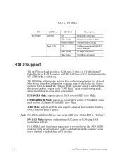
...the server board and to "disabled". NIC LEDs NIC NIC1/NIC2 LED Color Left LED Right LED LED State Off Solid Amber Blinking Amber Off Solid Amber Solid Green Description No network connection Network connection in EFI, you can set the AHCI legacy Option ROM to the backplane or I2C interface. 8 Intel® Server Board S5500BC User's Guide Table 3. COMPATIBILITY Mode: Supports up to configure RAID. AHCI Mode: Supports all SATA ports using RAID configuration software. The BIOS Setup utility provides multiple drive configuration options on the Advanced | Mass Storage Controller...
...the server board and to "disabled". NIC LEDs NIC NIC1/NIC2 LED Color Left LED Right LED LED State Off Solid Amber Blinking Amber Off Solid Amber Solid Green Description No network connection Network connection in EFI, you can set the AHCI legacy Option ROM to the backplane or I2C interface. 8 Intel® Server Board S5500BC User's Guide Table 3. COMPATIBILITY Mode: Supports up to configure RAID. AHCI Mode: Supports all SATA ports using RAID configuration software. The BIOS Setup utility provides multiple drive configuration options on the Advanced | Mass Storage Controller...
User Guide
Page 30
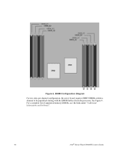
For a complete list of supported memory DIMMs, see the links under "Additional Information and Software". 10 Intel® Server Board S5500BC User's Guide See Figure 6. DIMM Configuration Diagram For two slots per channel configuration, the server board requires DDR3 DIMMs within a channel to be populated starting with the DIMM farthest from the processor. Figure 5.
For a complete list of supported memory DIMMs, see the links under "Additional Information and Software". 10 Intel® Server Board S5500BC User's Guide See Figure 6. DIMM Configuration Diagram For two slots per channel configuration, the server board requires DDR3 DIMMs within a channel to be populated starting with the DIMM farthest from the processor. Figure 5.

User Guide
Page 32
... memory sub-system. Hard Disk Drives The server board provides six SATA ports. Your supply must provide a minimum of 3.5 A of 400 W is placed on the SATA Key connector located on the managed server. The dedicated interface uses a separate LAN channel. These components provide a way to use a USB device anywhere on the network as if it was installed on the right side of the server. USB media redirection allows you can install the optional Intel® RAID Activation Key AXXRAKSW5. Optional...
... memory sub-system. Hard Disk Drives The server board provides six SATA ports. Your supply must provide a minimum of 3.5 A of 400 W is placed on the SATA Key connector located on the managed server. The dedicated interface uses a separate LAN channel. These components provide a way to use a USB device anywhere on the network as if it was installed on the right side of the server. USB media redirection allows you can install the optional Intel® RAID Activation Key AXXRAKSW5. Optional...
User Guide
Page 45
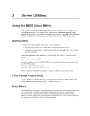
... the server board to the "Clear CMOS" position (enabled). Setup Menus Each BIOS Setup menu page contains a number of features. If a value cannot be changed for any reason, the feature's value field is corrupted, you will see this condition, the BIOS loads default values for CMOS and attempts to boot. 3 Server Utilities Using the BIOS Setup Utility This section describes the BIOS Setup Utility options, which you use to change these parameters. Starting Setup You can find details about specific BIOS setup screens...
... the server board to the "Clear CMOS" position (enabled). Setup Menus Each BIOS Setup menu page contains a number of features. If a value cannot be changed for any reason, the feature's value field is corrupted, you will see this condition, the BIOS loads default values for CMOS and attempts to boot. 3 Server Utilities Using the BIOS Setup Utility This section describes the BIOS Setup Utility options, which you use to change these parameters. Starting Setup You can find details about specific BIOS setup screens...
User Guide
Page 53
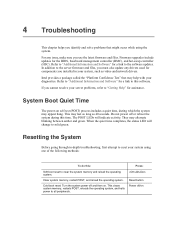
... as long as video and network drivers. Firmware upgrades include updates for components you use the latest firmware and files. Refer to "Additional Information and Software" for a link to all peripherals. Turn the system power off /on . Press: Reset button Power off and then on In addition to reset your diagnostics. If you identify and solve problems that may appear hang. Clear system memory, restart POST, and reload the operating system. Intel...
... as long as video and network drivers. Firmware upgrades include updates for components you use the latest firmware and files. Refer to "Additional Information and Software" for a link to all peripherals. Turn the system power off /on . Press: Reset button Power off and then on In addition to reset your diagnostics. If you identify and solve problems that may appear hang. Clear system memory, restart POST, and reload the operating system. Intel...
User Guide
Page 54
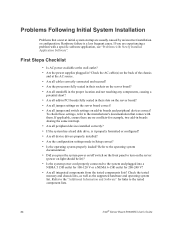
... peripheral devices installed correctly? • If the system has a hard disk drive, is a less frequent cause. If you press the system power on/off switch on the front panel to turn on the server (power on add-in ? Check the tested memory and chassis lists, as well as the supported hardware and operating system list. To check these settings, refer to the tested component lists. 34 Intel® Server Board S5500BC User's Guide Problems Following...
... peripheral devices installed correctly? • If the system has a hard disk drive, is a less frequent cause. If you press the system power on/off switch on the front panel to turn on the server (power on add-in ? Check the tested memory and chassis lists, as well as the supported hardware and operating system list. To check these settings, refer to the tested component lists. 34 Intel® Server Board S5500BC User's Guide Problems Following...
User Guide
Page 57
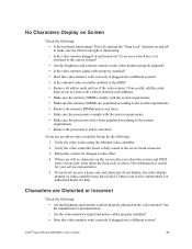
...; Is the keyboard functioning? Intel® Server Board S5500BC User's Guide 37 If successful, add the cards back in video controller board, do not display, the video display monitor or video controller may have been populated according to make sure the Num Lock light is it by turning the "Num Lock" function on the video monitor properly adjusted? • Is the video monitor signal cable properly installed? • Does this video monitor work correctly if plugged into a different system...
...; Is the keyboard functioning? Intel® Server Board S5500BC User's Guide 37 If successful, add the cards back in video controller board, do not display, the video display monitor or video controller may have been populated according to make sure the Num Lock light is it by turning the "Num Lock" function on the video monitor properly adjusted? • Is the video monitor signal cable properly installed? • Does this video monitor work correctly if plugged into a different system...
User Guide
Page 58
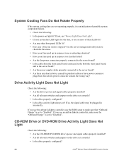
... panel board and to the server board? • Are the power supply cables properly connected to "Enabled". CD-ROM Drive or DVD-ROM Drive Activity Light Does Not Light Check the following : • Is the power-on light lit? If so, the signal cable may be plugged in response to a fan that "Onboard Floppy" is set to "Disabled". If you use the onboard diskette controller, use an add-in response to an overheating situation? • Have your system has LED lights...
... panel board and to the server board? • Are the power supply cables properly connected to "Enabled". CD-ROM Drive or DVD-ROM Drive Activity Light Does Not Light Check the following : • Is the power-on light lit? If so, the signal cable may be plugged in response to a fan that "Onboard Floppy" is set to "Disabled". If you use the onboard diskette controller, use an add-in response to an overheating situation? • Have your system has LED lights...
User Guide
Page 59
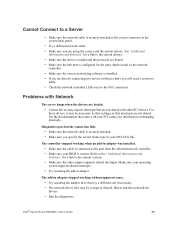
... correct connector at the system back panel. • Try a different network cable. • Make sure you are not shared with other adapter supports shared interrupts. then try a different slot if necessary. • The network driver files may be necessary to alter settings so that are using the correct and the current drivers. Intel® Server Board S5500BC User's Guide 39 Problems with Network The server hangs when the drivers are loaded. • Certain drivers...
... correct connector at the system back panel. • Try a different network cable. • Make sure you are not shared with other adapter supports shared interrupts. then try a different slot if necessary. • The network driver files may be necessary to alter settings so that are using the correct and the current drivers. Intel® Server Board S5500BC User's Guide 39 Problems with Network The server hangs when the drivers are loaded. • Certain drivers...
User Guide
Page 60
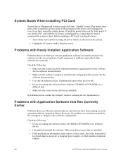
... properly installed and configured for the software. Problems with Newly Installed Application Software Problems that occur after the system hardware and software have turned the system power off the server power by file corruption or changes to the software-not the server hardware. Before installing a PCI card, you are installed. See the software documentation. • Make sure the software is unlikely, especially if other random component failures. 40 Intel® Server Board S5500BC User's Guide See the software documentation. • Use...
... properly installed and configured for the software. Problems with Newly Installed Application Software Problems that occur after the system hardware and software have turned the system power off the server power by file corruption or changes to the software-not the server hardware. Before installing a PCI card, you are installed. See the software documentation. • Make sure the software is unlikely, especially if other random component failures. 40 Intel® Server Board S5500BC User's Guide See the software documentation. • Use...
Quick Start Guide
Page 1
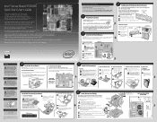
...://www.intel.com/go/serverbuilder and http://support.intel.com/support/motherboards/server. Warning Installation and service of this document before starting your finger tip to the reference chassis instructions. Components Processor must meet the following information will help you do not lay flat with the socket so that you integrate your Intel® Server Chassis and Intel® Server Board on the correct side of Board B. B Open the load plate...
...://www.intel.com/go/serverbuilder and http://support.intel.com/support/motherboards/server. Warning Installation and service of this document before starting your finger tip to the reference chassis instructions. Components Processor must meet the following information will help you do not lay flat with the socket so that you integrate your Intel® Server Chassis and Intel® Server Board on the correct side of Board B. B Open the load plate...


