
Product Specification
Page 5
...Layout 11 1.1.3 Block Diagram 13 1.2 Legacy Considerations 14 1.3 Online Support 14 1.4 Processor 14 1.5 Intel® Q67 Express Chipset 15 1.6 System Memory 15 1.6.1 Memory Configurations 16 1.7 Graphics Subsystem 18 ...Software 22 1.11.2 Audio Headers and Connectors 22 1.12 LAN Subsystem 24 1.12.1 Intel® 82579LM Gigabit Ethernet Controller 24 1.12.2 LAN Subsystem Software 24 1.12.3 ...Management and Security 28 1.15.1 Hardware Management Subsystem 28 1.15.2 Hardware Monitoring 28 1.15.3 Intel® vPro™ Technology 29 1.16 Power Management 33 1.16.1 ACPI 34 1.16.2 ...
...Layout 11 1.1.3 Block Diagram 13 1.2 Legacy Considerations 14 1.3 Online Support 14 1.4 Processor 14 1.5 Intel® Q67 Express Chipset 15 1.6 System Memory 15 1.6.1 Memory Configurations 16 1.7 Graphics Subsystem 18 ...Software 22 1.11.2 Audio Headers and Connectors 22 1.12 LAN Subsystem 24 1.12.1 Intel® 82579LM Gigabit Ethernet Controller 24 1.12.2 LAN Subsystem Software 24 1.12.3 ...Management and Security 28 1.15.1 Hardware Management Subsystem 28 1.15.2 Hardware Monitoring 28 1.15.3 Intel® vPro™ Technology 29 1.16 Power Management 33 1.16.1 ACPI 34 1.16.2 ...
Product Specification
Page 6
Intel Desktop Board DQ67SW Technical Product Specification 2.4 Intel® Management Engine BIOS Extension (Intel® MEBX) Reset Header 55 2.5 Mechanical Considerations 57 2.5.1 Form Factor 57 2.6 Electrical Considerations 58 2.6.1 Power Supply Considerations 58 2.6.2 ... Drive Password Security Feature 69 3.8 BIOS Security Features 70 4 Error Messages and Beep Codes 4.1 Speaker 73 4.2 BIOS Beep Codes 73 4.3 Front-panel Power LED Blink Codes 74 4.4 BIOS Error Messages 74 4.5 Port 80h POST Codes 75 5 Regulatory Compliance and Battery Disposal Information 5.1 Regulatory Compliance ...
Intel Desktop Board DQ67SW Technical Product Specification 2.4 Intel® Management Engine BIOS Extension (Intel® MEBX) Reset Header 55 2.5 Mechanical Considerations 57 2.5.1 Form Factor 57 2.6 Electrical Considerations 58 2.6.1 Power Supply Considerations 58 2.6.2 ... Drive Password Security Feature 69 3.8 BIOS Security Features 70 4 Error Messages and Beep Codes 4.1 Speaker 73 4.2 BIOS Beep Codes 73 4.3 Front-panel Power LED Blink Codes 74 4.4 BIOS Error Messages 74 4.5 Port 80h POST Codes 75 5 Regulatory Compliance and Battery Disposal Information 5.1 Regulatory Compliance ...

Product Specification
Page 7
... and Fan Headers 27 7. Component-side Connectors and Headers 45 11. LAN Connector LED States 25 5. Front Panel USB Header 48 16. States for Intel HD Audio 47 14. Intel MEBX Reset Header Signals 56 vii Back Panel Connectors 44 10. Feature Summary 9 2. S/PDIF Header 47 12. Internal Mono Speaker Header 47 13. Chassis...
... and Fan Headers 27 7. Component-side Connectors and Headers 45 11. LAN Connector LED States 25 5. Front Panel USB Header 48 16. States for Intel HD Audio 47 14. Intel MEBX Reset Header Signals 56 vii Back Panel Connectors 44 10. Feature Summary 9 2. S/PDIF Header 47 12. Internal Mono Speaker Header 47 13. Chassis...
Product Specification
Page 8
... for Components 61 31. BIOS Setup Program Menu Bar 64 33. Typical Port 80h POST Sequence 80 44. Thermal Considerations for BIOS Recovery 67 35. Intel Desktop Board DQ67SW Technical Product Specification 28. Recommended Power Supply Current Values 58 29. Front-panel Power LED Blink Codes 74 40.
... for Components 61 31. BIOS Setup Program Menu Bar 64 33. Typical Port 80h POST Sequence 80 44. Thermal Considerations for BIOS Recovery 67 35. Intel Desktop Board DQ67SW Technical Product Specification 28. Recommended Power Supply Current Values 58 29. Front-panel Power LED Blink Codes 74 40.
Product Specification
Page 9
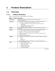
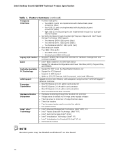
...millimeters by 243.84 millimeters]) • Intel® Core™ i7, Intel® Core™ i5, Intel® Core™ i3, and Intel® Pentium® processors in an ...support for processors with Intel® Graphics Technology) ― External graphics interface controller ― Integrated memory controller Intel® Q67 Express Chipset consisting of the Intel® Q67 Platform ...8226; Support for up to 95 W TDP: ― Integrated graphics processing (processors with Intel® Graphics Technology: ― DVI-I ― DVI-D ― DisplayPort* • Discrete graphics ...
...millimeters by 243.84 millimeters]) • Intel® Core™ i7, Intel® Core™ i5, Intel® Core™ i3, and Intel® Pentium® processors in an ...support for processors with Intel® Graphics Technology) ― External graphics interface controller ― Integrated memory controller Intel® Q67 Express Chipset consisting of the Intel® Q67 Platform ...8226; Support for up to 95 W TDP: ― Integrated graphics processing (processors with Intel® Graphics Technology: ― DVI-I ― DVI-D ― DisplayPort* • Discrete graphics ...
Product Specification
Page 10
...1394a port header ― One back panel IEEE 1394a port • Nuvoton* W83677HG-i Super I/O controller for hardware management and serial port support • Intel® BIOS resident in the SPI ...Intel® AMT) 7.0 • Intel® Trusted Execution Technology (Intel® TXT) • Intel® Fast Call for Help (Intel® FCFH) • Intel® Virtualization Technology (Intel® VT) • Intel® Virtualization for Directed I/O (Intel® VT-d) • KVM Remote Control NOTE Nuvoton parts may be labeled as Winbond* on the board. 10 Intel Desktop Board DQ67SW...
...1394a port header ― One back panel IEEE 1394a port • Nuvoton* W83677HG-i Super I/O controller for hardware management and serial port support • Intel® BIOS resident in the SPI ...Intel® AMT) 7.0 • Intel® Trusted Execution Technology (Intel® TXT) • Intel® Fast Call for Help (Intel® FCFH) • Intel® Virtualization Technology (Intel® VT) • Intel® Virtualization for Directed I/O (Intel® VT-d) • KVM Remote Control NOTE Nuvoton parts may be labeled as Winbond* on the board. 10 Intel Desktop Board DQ67SW...
Product Specification
Page 12
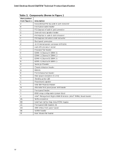
Intel Desktop Board DQ67SW Technical Product Specification Table 2. Components Shown in Figure 1 Item/callout from Figure 1 Description A Conventional PCI bus add-in card connector B Front panel audio header C PCI Express x4 add-in card connector D Internal mono speaker header E PCI Express x1 add-in card connector F PCI Express x16 add-in ...
Intel Desktop Board DQ67SW Technical Product Specification Table 2. Components Shown in Figure 1 Item/callout from Figure 1 Description A Conventional PCI bus add-in card connector B Front panel audio header C PCI Express x4 add-in card connector D Internal mono speaker header E PCI Express x1 add-in card connector F PCI Express x16 add-in ...
Product Specification
Page 19
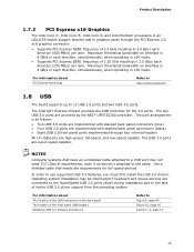
...device is 8 GB/s in x16 mode. • Supports PCI Express GEN1 frequency of native USB 3.0 driver support from the operating system. The Intel Q67 Express Chipset provides the USB controller for full-speed devices. The two USB 3.0 ports are super-speed capable. The port arrangement is 4 ...x16 mode. NOTES Computer systems that meets the requirements for the 2.0 ports. For information about The location of the USB connectors on the back panel The location of 2.5 GHz resulting in 5.0 Gb/s each direction, simultaneously, when operating in each direction (500 MB/s) per lane. In order...
...device is 8 GB/s in x16 mode. • Supports PCI Express GEN1 frequency of native USB 3.0 driver support from the operating system. The Intel Q67 Express Chipset provides the USB controller for full-speed devices. The two USB 3.0 ports are super-speed capable. The port arrangement is 4 ...x16 mode. NOTES Computer systems that meets the requirements for the 2.0 ports. For information about The location of the USB connectors on the back panel The location of 2.5 GHz resulting in 5.0 Gb/s each direction, simultaneously, when operating in each direction (500 MB/s) per lane. In order...
Product Specification
Page 22
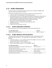
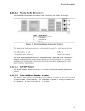
... through the Realtek ALC888S audio codec as well as the DisplayPort interface. Intel Desktop Board DQ67SW Technical Product Specification 1.11 Audio Subsystem The board supports Intel High Definition Audio through back panel jacks • Headphone and Mic in signals for the back panel audio jacks that enables the audio codec to recognize the device that...
... through the Realtek ALC888S audio codec as well as the DisplayPort interface. Intel Desktop Board DQ67SW Technical Product Specification 1.11 Audio Subsystem The board supports Intel High Definition Audio through back panel jacks • Headphone and Mic in signals for the back panel audio jacks that enables the audio codec to recognize the device that...
Product Specification
Page 23
..., low-power speaker for digital audio output. 1.11.2.3 Internal Mono Speaker Header The internal mono speaker header allows connection to Section 2.2.1, page 44 The front panel headphone output is capable of driving a speaker load of 8 Ohms at 1 W (rms) or 4 Ohms at 1.5 W (rms). 23 The subsystem is supported using a separate audio channel...
..., low-power speaker for digital audio output. 1.11.2.3 Internal Mono Speaker Header The internal mono speaker header allows connection to Section 2.2.1, page 44 The front panel headphone output is capable of driving a speaker load of 8 Ohms at 1 W (rms) or 4 Ohms at 1.5 W (rms). 23 The subsystem is supported using a separate audio channel...
Product Specification
Page 34
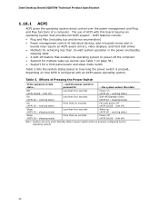
...) More than four seconds Soft-off (ACPI G2/G5 - pressed for a front panel power and sleep mode switch Table 5 lists the system states based on how long the power switch is pressed, depending on (ACPI G0 - Intel Desktop Board DQ67SW Technical Product Specification 1.16.1 ACPI ACPI gives the operating system direct control over...
...) More than four seconds Soft-off (ACPI G2/G5 - pressed for a front panel power and sleep mode switch Table 5 lists the system states based on how long the power switch is pressed, depending on (ACPI G0 - Intel Desktop Board DQ67SW Technical Product Specification 1.16.1 ACPI ACPI gives the operating system direct control over...
Product Specification
Page 39
... S5 state. 1.16.2.7 WAKE# Signal Wake-up device or event, the system quickly returns to be off (the power supply is off and the front panel power LED will appear to its last known wake state. The board supports the PCI Bus Power Management Interface Specification. When signaled by a wake-up...
... S5 state. 1.16.2.7 WAKE# Signal Wake-up device or event, the system quickly returns to be off (the power supply is off and the front panel power LED will appear to its last known wake state. The board supports the PCI Bus Power Management Interface Specification. When signaled by a wake-up...
Product Specification
Page 43
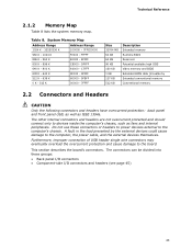
... by Extended conventionfal mem) ory Conventional memory 2.2 Connectors and Headers CAUTION Only the following connectors and headers have overcurrent protection: back panel and front panel USB, as well as fans and internal peripherals. FFFFF 896 K - 960 K E0000 - The other internal connectors and headers...protection and cause damage to the computer's chassis. DFFFF 640 K - 800 K A0000 - Do not use these groups: • Back panel I/O connectors • Component-side I/O connectors and headers (see page 45) 43 The connectors can be divided into these connectors or headers to...
... by Extended conventionfal mem) ory Conventional memory 2.2 Connectors and Headers CAUTION Only the following connectors and headers have overcurrent protection: back panel and front panel USB, as well as fans and internal peripherals. FFFFF 896 K - 960 K E0000 - The other internal connectors and headers...protection and cause damage to the computer's chassis. DFFFF 640 K - 800 K A0000 - Do not use these groups: • Back panel I/O connectors • Component-side I/O connectors and headers (see page 45) 43 The connectors can be divided into these connectors or headers to...
Product Specification
Page 44
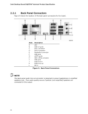
... USB ports eSATA ports IEEE 1394a connector USB ports Audio line in Audio line out Mic in Figure 9. Intel Desktop Board DQ67SW Technical Product Specification 2.2.1 Back Panel Connectors Figure 9 shows the location of the back panel connectors for the board. Poor audio quality occurs if passive (non-amplified) speakers are connected to power headphones...
... USB ports eSATA ports IEEE 1394a connector USB ports Audio line in Audio line out Mic in Figure 9. Intel Desktop Board DQ67SW Technical Product Specification 2.2.1 Back Panel Connectors Figure 9 shows the location of the back panel connectors for the board. Poor audio quality occurs if passive (non-amplified) speakers are connected to power headphones...
Product Specification
Page 46
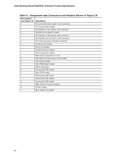
Intel Desktop Board DQ67SW Technical Product Specification Table 9. Component-side Connectors and Headers Shown in Figure 10 Item/callout from Figure 10 A B C D E F G H I J K L M N O Description PCI Conventional bus add-in card connector Front panel audio header PCI Express x4 bus add-in card connector Internal mono speaker header PCI Express x1 bus add-in card connector...
Intel Desktop Board DQ67SW Technical Product Specification Table 9. Component-side Connectors and Headers Shown in Figure 10 Item/callout from Figure 10 A B C D E F G H I J K L M N O Description PCI Conventional bus add-in card connector Front panel audio header PCI Express x4 bus add-in card connector Internal mono speaker header PCI Express x1 bus add-in card connector...
Product Specification
Page 47
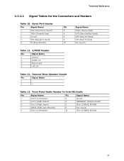
... pin) 3 +5V_DC Table 12. S/PDIF Header Pin Signal Name 1 Ground 2 S/PDIF out 3 Key (no pin) Table 11. Front Panel Audio Header for the Connectors and Headers Table 10. Technical Reference 2.2.2.1 Signal Tables for Intel HD Audio Pin Signal Name Pin Signal Name 1 [Port 1] Left channel 3 [Port 1] Right channel 5 [Port 2] Right channel 7 SENSE_SEND...
... pin) 3 +5V_DC Table 12. S/PDIF Header Pin Signal Name 1 Ground 2 S/PDIF out 3 Key (no pin) Table 11. Front Panel Audio Header for the Connectors and Headers Table 10. Technical Reference 2.2.2.1 Signal Tables for Intel HD Audio Pin Signal Name Pin Signal Name 1 [Port 1] Left channel 3 [Port 1] Right channel 5 [Port 2] Right channel 7 SENSE_SEND...

Product Specification
Page 48
Intel Desktop Board DQ67SW Technical Product Specification Table 14. Front Panel USB Header Pin Signal Name Pin 1 +5 VDC 2 3 D- 4 5 D+ 6 7 Ground 8 9 KEY (no pin) 9 FP_OUT_L 10 FP_RETURN_L NOTE Not all AC '97 signals are not supported. Front Panel Audio Header for AC '97 Audio Pin Signal Name Pin Signal Name 1 MIC 2 AUD_GND 3 MIC_BIAS 4 AUD_GND 5 FP_OUT_R 6 FP_RETURN_R 7 AUD_5V...
Intel Desktop Board DQ67SW Technical Product Specification Table 14. Front Panel USB Header Pin Signal Name Pin 1 +5 VDC 2 3 D- 4 5 D+ 6 7 Ground 8 9 KEY (no pin) 9 FP_OUT_L 10 FP_RETURN_L NOTE Not all AC '97 signals are not supported. Front Panel Audio Header for AC '97 Audio Pin Signal Name Pin Signal Name 1 MIC 2 AUD_GND 3 MIC_BIAS 4 AUD_GND 5 FP_OUT_R 6 FP_RETURN_R 7 AUD_5V...
Product Specification
Page 49
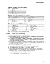
Front and Rear Chassis Fan Headers Pin 4-Wire Support 1 Ground 2 +12 V 3 FAN_TACH 4 FAN_CONTROL Pin 3-Wire Support 3 Ground 2 FAN_POWER 1 FAN_TACH N/A N/A Table 20. Front Panel IEEE 1394a Header Pin Signal Name Pin 1 Data A (positive) 2 3 Ground 4 5 Data B (positive) 6 7 +12V_DC 8 9 Key (no pin) 10 Note: The +12 V DC power on the desktop ...
Front and Rear Chassis Fan Headers Pin 4-Wire Support 1 Ground 2 +12 V 3 FAN_TACH 4 FAN_CONTROL Pin 3-Wire Support 3 Ground 2 FAN_POWER 1 FAN_TACH N/A N/A Table 20. Front Panel IEEE 1394a Header Pin Signal Name Pin 1 Data A (positive) 2 3 Ground 4 5 Data B (positive) 6 7 +12V_DC 8 9 Key (no pin) 10 Note: The +12 V DC power on the desktop ...
Product Specification
Page 51
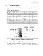
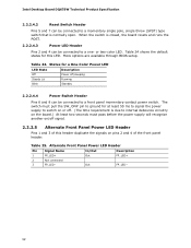
... LED 1 HD_PWR Out Hard disk LED pull-up to an onboard SATA connector. 51 Table 23 lists the signal names of the front panel header. Proper LED function requires a SATA hard drive or optical drive connected to +5 V 3 HDA# Out Hard disk active LED Reset...switch Ground Not connected Figure 11. Connection Diagram for the front panel header. Technical Reference 2.2.2.4 Front Panel Header This section describes the functions of the front panel header. Figure 11 is a connection diagram for Front Panel Header 2.2.2.4.1 Hard Drive Activity LED Header Pins 1 and 3 can...
... LED 1 HD_PWR Out Hard disk LED pull-up to an onboard SATA connector. 51 Table 23 lists the signal names of the front panel header. Proper LED function requires a SATA hard drive or optical drive connected to +5 V 3 HDA# Out Hard disk active LED Reset...switch Ground Not connected Figure 11. Connection Diagram for the front panel header. Technical Reference 2.2.2.4 Front Panel Header This section describes the functions of the front panel header. Figure 11 is a connection diagram for Front Panel Header 2.2.2.4.1 Hard Drive Activity LED Header Pins 1 and 3 can...
Product Specification
Page 52
...Header Pins 1 and 3 of the front panel header. Table 24 shows the default states for at least 50 ms to signal the power supply to switch on pins 2 and 4 of this LED. Table 24. Table 25. or two-color LED. Intel Desktop Board DQ67SW Technical Product Specification 2.2.2.4.2 Reset Switch Header ...Pins 5 and 7 can be connected to a front panel momentary-contact power switch.
...Header Pins 1 and 3 of the front panel header. Table 24 shows the default states for at least 50 ms to signal the power supply to switch on pins 2 and 4 of this LED. Table 24. Table 25. or two-color LED. Intel Desktop Board DQ67SW Technical Product Specification 2.2.2.4.2 Reset Switch Header ...Pins 5 and 7 can be connected to a front panel momentary-contact power switch.


