
Product Specification
Page 6
... System Management BIOS (SMBIOS 65 3.3 Legacy USB Support 65 3.4 BIOS Updates 66 3.4.1 Language Support 66 3.4.2 Custom Splash Screen 67 3.5 BIOS Recovery 67 3.6 Boot Options 68 3.6.1 Optical Drive Boot 68 3.6.2 Network Boot 68 3.6.3 Booting Without Attached Devices 68 3.6.4 Changing the Default Boot Device During POST 68 3.7 Hard Disk Drive Password Security Feature 69 3.8 BIOS Security Features 70 4 Error Messages and Beep Codes 4.1 Speaker 73 4.2 BIOS Beep Codes 73 4.3 Front-panel Power LED Blink Codes 74 4.4 BIOS Error Messages 74 4.5 Port 80h POST Codes 75 5 Regulatory...
... System Management BIOS (SMBIOS 65 3.3 Legacy USB Support 65 3.4 BIOS Updates 66 3.4.1 Language Support 66 3.4.2 Custom Splash Screen 67 3.5 BIOS Recovery 67 3.6 Boot Options 68 3.6.1 Optical Drive Boot 68 3.6.2 Network Boot 68 3.6.3 Booting Without Attached Devices 68 3.6.4 Changing the Default Boot Device During POST 68 3.7 Hard Disk Drive Password Security Feature 69 3.8 BIOS Security Features 70 4 Error Messages and Beep Codes 4.1 Speaker 73 4.2 BIOS Beep Codes 73 4.3 Front-panel Power LED Blink Codes 74 4.4 BIOS Error Messages 74 4.5 Port 80h POST Codes 75 5 Regulatory...

Product Specification
Page 7
... Setup Configuration Jumper Settings 55 27. Back Panel Audio Connector Options 23 5. Detailed System Memory Address Map 42 9. Back Panel Connectors 44 10. Board Dimensions 57 16. System Memory Map 43 9. Front Panel Audio Header for Front Panel Header 51 12. Front and Rear Chassis Fan Headers 49 20. LAN Connector LED Locations 25 6. Localized High Temperature Zones 61 Tables 1. Serial Port Header 47 11. Processor Core Power Connector 50 22. Alternate Front Panel Power LED Header 52 26. Memory Channel and DIMM Configuration 17 4. Connection Diagram for Intel...
... Setup Configuration Jumper Settings 55 27. Back Panel Audio Connector Options 23 5. Detailed System Memory Address Map 42 9. Back Panel Connectors 44 10. Board Dimensions 57 16. System Memory Map 43 9. Front Panel Audio Header for Front Panel Header 51 12. Front and Rear Chassis Fan Headers 49 20. LAN Connector LED Locations 25 6. Localized High Temperature Zones 61 Tables 1. Serial Port Header 47 11. Processor Core Power Connector 50 22. Alternate Front Panel Power LED Header 52 26. Memory Channel and DIMM Configuration 17 4. Connection Diagram for Intel...
Product Specification
Page 8
... Considerations for BIOS Recovery 67 35. BIOS Setup Program Menu Bar 64 33. Master Key and User Hard Drive Password Functions 69 37. Front-panel Power LED Blink Codes 74 40. Intel Desktop Board DQ67SW Technical Product Specification 28. BIOS Setup Program Function Keys 64 34. Port 80h POST Code Ranges 75 42. Safety Standards 81 45. Typical Port 80h POST Sequence 80 44. Boot Device Menu Options 68 36. EMC Regulations 85 46. Fan Header Current Capability 59 30. Recommended Power Supply Current Values...
... Considerations for BIOS Recovery 67 35. BIOS Setup Program Menu Bar 64 33. Master Key and User Hard Drive Password Functions 69 37. Front-panel Power LED Blink Codes 74 40. Intel Desktop Board DQ67SW Technical Product Specification 28. BIOS Setup Program Function Keys 64 34. Port 80h POST Code Ranges 75 42. Safety Standards 81 45. Typical Port 80h POST Sequence 80 44. Boot Device Menu Options 68 36. EMC Regulations 85 46. Fan Header Current Capability 59 30. Recommended Power Supply Current Values...
Product Specification
Page 14
... socket. For information about ... Refer to support the Intel Core i7, Intel Core i5, Intel Core i3, and Intel Pentium processors in the future. See the Intel web site listed below for providing power to -date list of supported processors. Supported processors Refer to ) the following: • No floppy drive connector • No PS/2 connector • No Parallel ATA (PATA) IDE drive connector 1.3 Online Support To find information about ... Intel Desktop Board DQ67SW Technical Product Specification 1.2 Legacy Considerations This board differs from other Intel Desktop Board...
... socket. For information about ... Refer to support the Intel Core i7, Intel Core i5, Intel Core i3, and Intel Pentium processors in the future. See the Intel web site listed below for providing power to -date list of supported processors. Supported processors Refer to ) the following: • No floppy drive connector • No PS/2 connector • No Parallel ATA (PATA) IDE drive connector 1.3 Online Support To find information about ... Intel Desktop Board DQ67SW Technical Product Specification 1.2 Legacy Considerations This board differs from other Intel Desktop Board...
Product Specification
Page 20
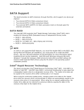
... preferred mode for more information, see: http://www.serialata.org/. The SATA controller can operate in both AHCI and RAID without the need to install separate RAID drivers using the Windows* XP, Windows Vista*, and Windows 7* operating systems. For more information about The location of the SATA connectors Refer to Figure 10, page 45 1.9.1.1 Serial ATA RAID The board supports the Intel Rapid Storage Technology (Intel RST) which support one device per connector: • Two internal SATA 6 Gb/s ports...
... preferred mode for more information, see: http://www.serialata.org/. The SATA controller can operate in both AHCI and RAID without the need to install separate RAID drivers using the Windows* XP, Windows Vista*, and Windows 7* operating systems. For more information about The location of the SATA connectors Refer to Figure 10, page 45 1.9.1.1 Serial ATA RAID The board supports the Intel Rapid Storage Technology (Intel RST) which support one device per connector: • Two internal SATA 6 Gb/s ports...
Product Specification
Page 53
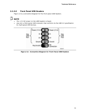
NOTE • The +5 V DC power on the USB headers is a connection diagram for the front panel USB headers. Figure 12. Connection Diagram for Front Panel USB Headers 53 Technical Reference 2.2.2.6 Front Panel USB Headers Figure 12 is fused. • Use only a front panel USB connector that conforms to the USB 2.0 specification for high-speed USB devices.
NOTE • The +5 V DC power on the USB headers is a connection diagram for the front panel USB headers. Figure 12. Connection Diagram for Front Panel USB Headers 53 Technical Reference 2.2.2.6 Front Panel USB Headers Figure 12 is fused. • Use only a front panel USB connector that conforms to the USB 2.0 specification for high-speed USB devices.
Product Specification
Page 63
... the HDD if RAID is used to view and change the BIOS settings for the computer. This is accessed by pressing the key after the Power-On Self-Test (POST) memory test begins and before the operating system boot begins. The menu bar is shown below. CAUTION Resetting the BIOS to defaults may result in a 64 Mbit (8,192 KB) Serial Peripheral Interface Flash Memory (SPI Flash) device which can be updated using a set of utilities...
... the HDD if RAID is used to view and change the BIOS settings for the computer. This is accessed by pressing the key after the Power-On Self-Test (POST) memory test begins and before the operating system boot begins. The menu bar is shown below. CAUTION Resetting the BIOS to defaults may result in a 64 Mbit (8,192 KB) Serial Peripheral Interface Flash Memory (SPI Flash) device which can be updated using a set of utilities...
Product Specification
Page 69
... not support Hard Disk Drive Password Security feature, the drive will be accessible. 69 The Master Key hard disk drive password, when installed, will have three attempts to another SATA port or computer that the User hard disk drive password is set, POST execution will pause with the following prompt to force the user to enter the Master Key or User hard disk drive password: Enter Hard Disk Drive Password: Upon successful entry of the Master Key or User hard disk drive password, the system will continue with the message: Hard Disk Drive Password Entry Error A manual power...
... not support Hard Disk Drive Password Security feature, the drive will be accessible. 69 The Master Key hard disk drive password, when installed, will have three attempts to another SATA port or computer that the User hard disk drive password is set, POST execution will pause with the following prompt to force the user to enter the Master Key or User hard disk drive password: Enter Hard Disk Drive Password: Upon successful entry of the Master Key or User hard disk drive password, the system will continue with the message: Hard Disk Drive Password Entry Error A manual power...
Product Specification
Page 70
... the user restricted access to which password is entered. • Setting the user password restricts who can boot the computer. Intel Desktop Board DQ67SW Technical Product Specification NOTE Hard Disk Drive Password Security is not supported in the BIOS Setup program. Users have access to Setup respective to Setup. • If both passwords are set , pressing the key at the password prompt of BIOS Hard Disk Drive Password support. 3.8 BIOS Security Features The BIOS includes security features that restrict access to view and change all the Setup options in PCH RAID mode...
... the user restricted access to which password is entered. • Setting the user password restricts who can boot the computer. Intel Desktop Board DQ67SW Technical Product Specification NOTE Hard Disk Drive Password Security is not supported in the BIOS Setup program. Users have access to Setup respective to Setup. • If both passwords are set , pressing the key at the password prompt of BIOS Hard Disk Drive Password support. 3.8 BIOS Security Features The BIOS includes security features that restrict access to view and change all the Setup options in PCH RAID mode...
Product Specification
Page 74
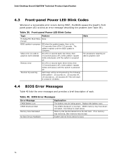
... power. Intel Desktop Board DQ67SW Technical Product Specification 4.3 Front-panel Power LED Blink Codes Whenever a recoverable error occurs during POST, the BIOS causes the board's front panel power LED to reset values. The pattern repeats until the system is powered off . Video error (no memory was removed, then memory may be accompanied by the following blink pattern: .25 seconds on, .25 seconds off, .25 seconds on for 0.5 seconds. This will be bad. Replace the battery soon. CMOS...
... power. Intel Desktop Board DQ67SW Technical Product Specification 4.3 Front-panel Power LED Blink Codes Whenever a recoverable error occurs during POST, the BIOS causes the board's front panel power LED to reset values. The pattern repeats until the system is powered off . Video error (no memory was removed, then memory may be accompanied by the following blink pattern: .25 seconds on, .25 seconds off, .25 seconds on for 0.5 seconds. This will be bad. Replace the battery soon. CMOS...
Product Specification
Page 75
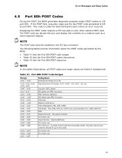
... the tables listed above, all POST codes and range values are listed in hexadecimal. Security (SEC) phase PEI phase pre MRC execution MRC memory detection PEI phase post MRC execution Recovery Platform DXE driver CPU Initialization (PEI, DXE, SMM) I /O port 80h. Not that critical since consoles should be installed in card, often called a POST card. This code is an unrecoverable error. For future use Input devices: Keyboard/Mouse. BDS...
... the tables listed above, all POST codes and range values are listed in hexadecimal. Security (SEC) phase PEI phase pre MRC execution MRC memory detection PEI phase post MRC execution Recovery Platform DXE driver CPU Initialization (PEI, DXE, SMM) I /O port 80h. Not that critical since consoles should be installed in card, often called a POST card. This code is an unrecoverable error. For future use Input devices: Keyboard/Mouse. BDS...
English Product Guide
Page 3
may not be supported without further evaluation by Intel. Document Organization The chapters in this manual: CAUTION Cautions warn the user about board layout, component installation, BIOS update, and regulatory requirements for Intel® Desktop Board DQ67SW. Use Only for Intended Applications All Intel Desktop Boards are arranged as Information Technology Equipment (I.T.E.) for use in personal computers (PC) for technically qualified personnel. Preface This Product Guide gives information about how to...
may not be supported without further evaluation by Intel. Document Organization The chapters in this manual: CAUTION Cautions warn the user about board layout, component installation, BIOS update, and regulatory requirements for Intel® Desktop Board DQ67SW. Use Only for Intended Applications All Intel Desktop Boards are arranged as Information Technology Equipment (I.T.E.) for use in personal computers (PC) for technically qualified personnel. Preface This Product Guide gives information about how to...
English Product Guide
Page 5
... Auto Configuration 22 PCI*/PCI Express Auto Configuration 22 BIOS Security Passwords 22 Hard Disk Drive Passwords 23 Platform Management and Protection 25 Intel® vPro™ Technology 25 Intel® Active Management Technology 25 Intel® Virtualization Technology 28 Intel® Trusted Execution Technology 28 Intel® Fast Call for Help 28 Trusted Platform Module (TPM 28 Fan Speed Control and Hardware Monitoring 29 Power Management 29 Software Support 29 Hardware Support 29 Onboard Speaker 32 Real-Time Clock Subsystem 32 2 Installing and Replacing Desktop Board...
... Auto Configuration 22 PCI*/PCI Express Auto Configuration 22 BIOS Security Passwords 22 Hard Disk Drive Passwords 23 Platform Management and Protection 25 Intel® vPro™ Technology 25 Intel® Active Management Technology 25 Intel® Virtualization Technology 28 Intel® Trusted Execution Technology 28 Intel® Fast Call for Help 28 Trusted Platform Module (TPM 28 Fan Speed Control and Hardware Monitoring 29 Power Management 29 Software Support 29 Hardware Support 29 Onboard Speaker 32 Real-Time Clock Subsystem 32 2 Installing and Replacing Desktop Board...
English Product Guide
Page 6
... Mono Speaker Header 52 Serial Header 52 Chassis Intrusion Header 52 Alternate Front Panel Power LED Header 53 Front Panel Header 53 Intel FCFH Header 53 Front Panel USB 2.0 Headers 54 IEEE 1394a Header 54 Connecting to the Audio System 55 Connecting Chassis Fan and Power Supply Cables 56 Connecting Chassis Fan Cables 56 Connecting Power Supply Cables 57 Setting the BIOS Configuration Jumper 58 Clearing Passwords in the BIOS Setup Program 59 Replacing the Battery 60 3 Updating the BIOS Updating the BIOS with the Intel® Express BIOS Update Utility 67 Updating the BIOS Using...
... Mono Speaker Header 52 Serial Header 52 Chassis Intrusion Header 52 Alternate Front Panel Power LED Header 53 Front Panel Header 53 Intel FCFH Header 53 Front Panel USB 2.0 Headers 54 IEEE 1394a Header 54 Connecting to the Audio System 55 Connecting Chassis Fan and Power Supply Cables 56 Connecting Chassis Fan Cables 56 Connecting Power Supply Cables 57 Setting the BIOS Configuration Jumper 58 Clearing Passwords in the BIOS Setup Program 59 Replacing the Battery 60 3 Updating the BIOS Updating the BIOS with the Intel® Express BIOS Update Utility 67 Updating the BIOS Using...
English Product Guide
Page 7
... 85 Figures 1. Install the Processor 39 11. Removing a PCI Express x16 Graphics Card 48 20. Internal Headers 50 22. Location of the Standby Power Indicator 31 5. Location of the BIOS Configuration Jumper Block 58 26. Lift the Load Plate 38 9. Connecting the Processor Fan Heat Sink Power Cable to the Processor Fan Header 41 13. Use DDR3 DIMMs 44 17. Location of the Intel MEBX Reset Header 27 4. Removing the Battery 65 27. Example Dual Channel Memory Configuration with Two DIMMs 42 14. Intel Desktop Board DQ67SW China RoHS...
... 85 Figures 1. Install the Processor 39 11. Removing a PCI Express x16 Graphics Card 48 20. Internal Headers 50 22. Location of the Standby Power Indicator 31 5. Location of the BIOS Configuration Jumper Block 58 26. Lift the Load Plate 38 9. Connecting the Processor Fan Heat Sink Power Cable to the Processor Fan Header 41 13. Use DDR3 DIMMs 44 17. Location of the Intel MEBX Reset Header 27 4. Removing the Battery 65 27. Example Dual Channel Memory Configuration with Two DIMMs 42 14. Intel Desktop Board DQ67SW China RoHS...
English Product Guide
Page 20
...; Two internal SATA 3.0 Gb/s connectors (black) • Two external SATA (eSATA) 3.0 Gb/s connectors (red) on the back panel for external connections SATA RAID The Intel Q67 PCH supports Intel® Rapid Storage Technology (Intel® RST) which enables the following RAID (Redundant Array of Intel RST. Both Microsoft Windows Vista and Microsoft Windows 7 include the necessary RAID drivers for more information about installing drivers during Microsoft Windows XP installation, you must press F6 to a designated recovery drive. Intel RRT uses RAID...
...; Two internal SATA 3.0 Gb/s connectors (black) • Two external SATA (eSATA) 3.0 Gb/s connectors (red) on the back panel for external connections SATA RAID The Intel Q67 PCH supports Intel® Rapid Storage Technology (Intel® RST) which enables the following RAID (Redundant Array of Intel RST. Both Microsoft Windows Vista and Microsoft Windows 7 include the necessary RAID drivers for more information about installing drivers during Microsoft Windows XP installation, you must press F6 to a designated recovery drive. Intel RRT uses RAID...
English Product Guide
Page 22
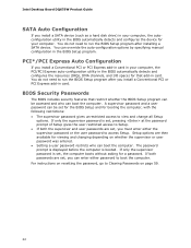
...or user password was entered. • Setting a user password restricts who can boot the computer. Setup options are then available for that restrict whether the BIOS Setup program can enter either the supervisor password or the user password to view and change all Setup options. For instructions on resetting the password, go to boot the computer. Intel Desktop Board DQ67SW Product Guide SATA Auto Configuration If you install a SATA device (such as a hard disk drive) in your computer, the autoconfiguration utility in the BIOS Setup program. PCI*/PCI Express Auto Configuration If...
...or user password was entered. • Setting a user password restricts who can boot the computer. Setup options are then available for that restrict whether the BIOS Setup program can enter either the supervisor password or the user password to view and change all Setup options. For instructions on resetting the password, go to boot the computer. Intel Desktop Board DQ67SW Product Guide SATA Auto Configuration If you install a SATA device (such as a hard disk drive) in your computer, the autoconfiguration utility in the BIOS Setup program. PCI*/PCI Express Auto Configuration If...
English Product Guide
Page 23
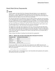
...set, will be used in BIOS Setup and are stored on the hard disk drive, if the drive is set , will not lock the hard disk drive. Desktop Board Features Hard Disk Drive Passwords NOTE On this board, the Hard Disk Drive Password Security feature is only supported on resume from S3. The Master Key hard disk drive password is entered. The board's Hard Disk Drive Password Security feature blocks read and write accesses to enter the Master Key or User hard disk drive password: Enter Hard Disk Drive Password: Upon successful entry of setting the hard disk drive passwords. Hard disk drive...
...set, will be used in BIOS Setup and are stored on the hard disk drive, if the drive is set , will not lock the hard disk drive. Desktop Board Features Hard Disk Drive Passwords NOTE On this board, the Hard Disk Drive Password Security feature is only supported on resume from S3. The Master Key hard disk drive password is entered. The board's Hard Disk Drive Password Security feature blocks read and write accesses to enter the Master Key or User hard disk drive password: Enter Hard Disk Drive Password: Upon successful entry of setting the hard disk drive passwords. Hard disk drive...
English Product Guide
Page 29
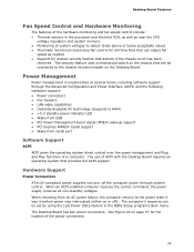
... the BIOS Setup program's Boot menu. Hardware Support Power Connectors ATX12V-compliant power supplies can turn off ). See Figure 24 on page 57 for chassis security feature that provides full ACPI support. Desktop Board Features Fan Speed Control and Hardware Monitoring The features of the hardware monitoring and fan speed control include: • Thermal sensors in the processor and the Intel PCH, as well as near the CPU voltage regulators and system memory • Monitoring of system voltages to the power...
... the BIOS Setup program's Boot menu. Hardware Support Power Connectors ATX12V-compliant power supplies can turn off ). See Figure 24 on page 57 for chassis security feature that provides full ACPI support. Desktop Board Features Fan Speed Control and Hardware Monitoring The features of the hardware monitoring and fan speed control include: • Thermal sensors in the processor and the Intel PCH, as well as near the CPU voltage regulators and system memory • Monitoring of system voltages to the power...
English Product Guide
Page 59
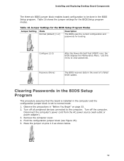
... in the BIOS Setup program. Remove the computer cover. 4. Installing and Replacing Desktop Board Components The three-pin BIOS jumper block enables board configuration to normal mode. 1. Recovery (None) The BIOS recovers data in "Before You Begin" on pins 2-3 as shown below. 59 Disconnect the computer's power cord from the AC power source (wall outlet or power adapter). 3. Use this menu to the computer. Table 16. Turn off all peripheral devices connected to clear passwords. Turn off the...
... in the BIOS Setup program. Remove the computer cover. 4. Installing and Replacing Desktop Board Components The three-pin BIOS jumper block enables board configuration to normal mode. 1. Recovery (None) The BIOS recovers data in "Before You Begin" on pins 2-3 as shown below. 59 Disconnect the computer's power cord from the AC power source (wall outlet or power adapter). 3. Use this menu to the computer. Table 16. Turn off all peripheral devices connected to clear passwords. Turn off the...


