

DP67DE Technical Product Specification
Page 8
...3.5 Legacy USB Support 61 3.6 BIOS Updates 62 3.6.1 Language Support 62 3.6.2 Custom Splash Screen 63 3.7 BIOS Recovery 63 3.8 Boot Options 64 3.8.1 Optical Drive Boot 64 3.8.2 Network Boot 64 3.8.3 Booting Without Attached Devices 64 3.8.4 Changing the Default Boot Device During POST 64 3.9 Adjusting Boot Speed 65 3.9.1 Peripheral Selection and Configuration 65 3.9.2 BIOS Boot Optimizations 65 3.10 BIOS Security Features 66 3.11 BIOS Performance Features 67 4 Error Messages and Beep Codes 4.1 Speaker 69 4.2 BIOS Beep Codes 69 4.3 Front-panel Power LED Blink Codes 70 4.4 BIOS...
...3.5 Legacy USB Support 61 3.6 BIOS Updates 62 3.6.1 Language Support 62 3.6.2 Custom Splash Screen 63 3.7 BIOS Recovery 63 3.8 Boot Options 64 3.8.1 Optical Drive Boot 64 3.8.2 Network Boot 64 3.8.3 Booting Without Attached Devices 64 3.8.4 Changing the Default Boot Device During POST 64 3.9 Adjusting Boot Speed 65 3.9.1 Peripheral Selection and Configuration 65 3.9.2 BIOS Boot Optimizations 65 3.10 BIOS Security Features 66 3.11 BIOS Performance Features 67 4 Error Messages and Beep Codes 4.1 Speaker 69 4.2 BIOS Beep Codes 69 4.3 Front-panel Power LED Blink Codes 70 4.4 BIOS...
DP67DE Technical Product Specification
Page 10
... Front Panel Power/Sleep LED Header 48 27. BIOS Setup Configuration Jumper Settings 51 28. BIOS Error Messages 70 41. Chassis Intrusion Header 44 18. Main Power Connector 46 23. Front Panel Header 47 24. Thermal Considerations for Components 56 32. BIOS Setup Program Function Keys 60 35. Safety Standards 77 45. Intel Desktop Board DP67DE Technical Product Specification 17. Processor Core Power Connector 46 22. Tcontrol Values for Components 56 31. Port 80h POST Code Ranges 71 42. Port 80h POST Codes 72 43. Environmental Specifications 57...
... Front Panel Power/Sleep LED Header 48 27. BIOS Setup Configuration Jumper Settings 51 28. BIOS Error Messages 70 41. Chassis Intrusion Header 44 18. Main Power Connector 46 23. Front Panel Header 47 24. Thermal Considerations for Components 56 32. BIOS Setup Program Function Keys 60 35. Safety Standards 77 45. Intel Desktop Board DP67DE Technical Product Specification 17. Processor Core Power Connector 46 22. Tcontrol Values for Components 56 31. Port 80h POST Code Ranges 71 42. Port 80h POST Codes 72 43. Environmental Specifications 57...
DP67DE Technical Product Specification
Page 11
... (PCH) Graphics Audio Peripheral Interfaces Discrete graphics support for PCI Express 2.0 x16 add-in graphics card 10-channel (7.1 + 2) Intel High Definition Audio via the Realtek ALC892 audio codec • Two USB 3.0 ports are implemented with stacked back panel connectors (blue) • Fourteen USB 2.0 ports: ― Six ports are implemented with stacked back panel connectors (black) ― Eight front panel ports implemented through four internal headers • Two SATA 6.0 Gb/s interfaces through Intel P67 Express Chipset with Intel® Rapid Storage Technology RAID support (blue...
... (PCH) Graphics Audio Peripheral Interfaces Discrete graphics support for PCI Express 2.0 x16 add-in graphics card 10-channel (7.1 + 2) Intel High Definition Audio via the Realtek ALC892 audio codec • Two USB 3.0 ports are implemented with stacked back panel connectors (blue) • Fourteen USB 2.0 ports: ― Six ports are implemented with stacked back panel connectors (black) ― Eight front panel ports implemented through four internal headers • Two SATA 6.0 Gb/s interfaces through Intel P67 Express Chipset with Intel® Rapid Storage Technology RAID support (blue...

DP67DE Technical Product Specification
Page 18
.... • Support for 1.35 V Low Voltage DDR3 (new JEDEC specification) • Two independent memory channels with interleaved mode support • Unbuffered, single-sided or double-sided DIMMs with the following memory features: • 1.5 V DDR3 SDRAM DIMMs with gold plated contacts, with the option to raise the voltage to : http://support.intel.com/support/motherboards/desktop/sb /CS-025414.htm 18 Supported Memory Configurations DIMM Capacity SDRAM Configuration (Note) Density...
.... • Support for 1.35 V Low Voltage DDR3 (new JEDEC specification) • Two independent memory channels with interleaved mode support • Unbuffered, single-sided or double-sided DIMMs with the following memory features: • 1.5 V DDR3 SDRAM DIMMs with gold plated contacts, with the option to raise the voltage to : http://support.intel.com/support/motherboards/desktop/sb /CS-025414.htm 18 Supported Memory Configurations DIMM Capacity SDRAM Configuration (Note) Density...
DP67DE Technical Product Specification
Page 23
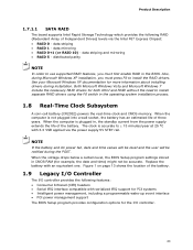
... 13 shows the location of the battery. Product Description 1.7.1.1 SATA RAID The board supports Intel Rapid Storage Technology which provides the following features: • Consumer Infrared (CIR) headers • Serial IRQ interface compatible with serialized IRQ support for PCI systems • Intelligent power management, including a programmable wake-up event interface • PCI power management support The BIOS Setup program provides configuration options for more information about installing drivers during installation. NOTE If the battery and AC power fail, date...
... 13 shows the location of the battery. Product Description 1.7.1.1 SATA RAID The board supports Intel Rapid Storage Technology which provides the following features: • Consumer Infrared (CIR) headers • Serial IRQ interface compatible with serialized IRQ support for PCI systems • Intelligent power management, including a programmable wake-up event interface • PCI power management support The BIOS Setup program provides configuration options for more information about installing drivers during installation. NOTE If the battery and AC power fail, date...

DP67DE Technical Product Specification
Page 26
... Express Chipset • RJ-45 LAN connector with integrated status LEDs Additional features of the LAN subsystem include: • CSMA/CD protocol engine • LAN connect interface between the PCH and the LAN controller • PCI Conventional bus power management ACPI technology support LAN wake capabilities • LAN subsystem software For information about LAN software and drivers Refer to http://downloadcenter.intel.com 1.11.1 Intel® 82579V Gigabit Ethernet Controller The Intel 82579V Gigabit Ethernet Controller supports...
... Express Chipset • RJ-45 LAN connector with integrated status LEDs Additional features of the LAN subsystem include: • CSMA/CD protocol engine • LAN connect interface between the PCH and the LAN controller • PCI Conventional bus power management ACPI technology support LAN wake capabilities • LAN subsystem software For information about LAN software and drivers Refer to http://downloadcenter.intel.com 1.11.1 Intel® 82579V Gigabit Ethernet Controller The Intel 82579V Gigabit Ethernet Controller supports...
DP67DE Technical Product Specification
Page 49
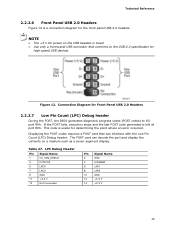
... 2.2.2.6 Front Panel USB 2.0 Headers Figure 12 is a connection diagram for determining the point where an error occurred. NOTE • The +5 V DC power on a medium such as a seven-segment display. If the POST fails, execution stops and the last POST code generated is useful for the front panel USB 2.0 headers. The POST card can decode the port and display the contents on the USB headers is fused. • Use only a front panel USB connector that can...
... 2.2.2.6 Front Panel USB 2.0 Headers Figure 12 is a connection diagram for determining the point where an error occurred. NOTE • The +5 V DC power on a medium such as a seven-segment display. If the POST fails, execution stops and the last POST code generated is useful for the front panel USB 2.0 headers. The POST card can decode the port and display the contents on the USB headers is fused. • Use only a front panel USB connector that can...
DP67DE Technical Product Specification
Page 59
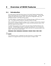
.... When the BIOS Setup configuration jumper is set to put the board in the BIOS and reports if the two match. 3 Overview of BIOS and a revision code. The SPI Flash contains the BIOS Setup program, POST, the PCI auto-configuration utility, LAN EEPROM information, and Plug and Play support. Maintenance Main Configuration Performance Security Power Boot Exit NOTE The maintenance menu is displayed only when the board is powered-up, the BIOS compares the CPU version and the microcode version in configure mode. 59
.... When the BIOS Setup configuration jumper is set to put the board in the BIOS and reports if the two match. 3 Overview of BIOS and a revision code. The SPI Flash contains the BIOS Setup program, POST, the PCI auto-configuration utility, LAN EEPROM information, and Plug and Play support. Maintenance Main Configuration Performance Security Power Boot Exit NOTE The maintenance menu is displayed only when the board is powered-up, the BIOS compares the CPU version and the microcode version in configure mode. 59
DP67DE Technical Product Specification
Page 60
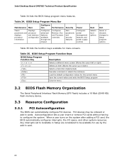
BIOS Setup Program Menu Bar Maintenance Main Configura- When a user turns on the system after adding a PCI card, the BIOS automatically configures interrupts, the I/O space, and other system resources. Table 34. tion Performance Security Clears passwords and displays processor information Displays processor and memory configuration Configures advanced features available through the chipset Configures Memory, Bus and Processor overrides Sets passwords and security features Power Configures power management features and power supply controls Boot Selects boot options Exit ...
BIOS Setup Program Menu Bar Maintenance Main Configura- When a user turns on the system after adding a PCI card, the BIOS automatically configures interrupts, the I/O space, and other system resources. Table 34. tion Performance Security Clears passwords and displays processor information Displays processor and memory configuration Configures advanced features available through the chipset Configures Memory, Bus and Processor overrides Sets passwords and security features Power Configures power management features and power supply controls Boot Selects boot options Exit ...
DP67DE Technical Product Specification
Page 71
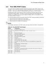
... 0xA0 - 0xAF For future use 0xB0 - 0xBF Boot Devices: Includes fixed media and removable media. Start with the Low Pin Count (LPC) Debug header. Table 42. Error Messages and Beep Codes 4.5 Port 80h POST Codes During the POST, the BIOS generates diagnostic progress codes (POST codes) to I /O Buses: PCI, USB, ATA etc. 0x5F is an unrecoverable error. If the POST fails, execution stops and the last POST code generated is useful for determining the point...
... 0xA0 - 0xAF For future use 0xB0 - 0xBF Boot Devices: Includes fixed media and removable media. Start with the Low Pin Count (LPC) Debug header. Table 42. Error Messages and Beep Codes 4.5 Port 80h POST Codes During the POST, the BIOS generates diagnostic progress codes (POST codes) to I /O Buses: PCI, USB, ATA etc. 0x5F is an unrecoverable error. If the POST fails, execution stops and the last POST code generated is useful for determining the point...
DP67DE Specification Update
Page 6
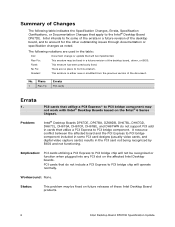
... a future revision of the desktop board, driver, or BIOS. PCI cards that do not support PCI add in the PCI card not being recognized by BIOS and not functioning. PCI cards that utilize a PCI Express* to the Intel® Desktop Board DP67DE. Shaded: This erratum is either new or modified from the previous version of Changes The following notations are no plans to PCI bridge chip will operate normally. Problem: Intel® Desktop Boards DP67DE, DP67BA, DZ68DB, DH67BL, DH67GD...
... a future revision of the desktop board, driver, or BIOS. PCI cards that do not support PCI add in the PCI card not being recognized by BIOS and not functioning. PCI cards that utilize a PCI Express* to the Intel® Desktop Board DP67DE. Shaded: This erratum is either new or modified from the previous version of Changes The following notations are no plans to PCI bridge chip will operate normally. Problem: Intel® Desktop Boards DP67DE, DP67BA, DZ68DB, DH67BL, DH67GD...

English Product Guide
Page 3
... warn the user about board layout, component installation, BIOS update, and regulatory requirements for installation in homes, offices, schools, computer rooms, and similar locations. Use Only for Intended Applications All Intel Desktop Boards are used in this product for other PC or embedded non-PC applications or other hardware components 3 Updating the BIOS: instructions on how to update the BIOS A Error Messages and Indicators: information about BIOS error messages and beep codes B Regulatory...
... warn the user about board layout, component installation, BIOS update, and regulatory requirements for installation in homes, offices, schools, computer rooms, and similar locations. Use Only for Intended Applications All Intel Desktop Boards are used in this product for other PC or embedded non-PC applications or other hardware components 3 Updating the BIOS: instructions on how to update the BIOS A Error Messages and Indicators: information about BIOS error messages and beep codes B Regulatory...
English Product Guide
Page 5
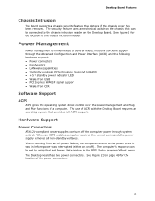
... Operating Systems 11 Desktop Board Components 12 Processor ...14 Intel® P67 Express Chipset 15 Main Memory...15 Graphics Support 16 Audio Subsystem 16 LAN Subsystem 17 USB Support ...18 SATA Support...18 Expandability...18 Legacy I/O ...19 BIOS ...19 SATA Auto Configuration 19 PCI*/PCI Express Auto Configuration 19 Security Passwords 20 Hardware Management 20 Hardware Monitoring and Fan Speed Control 20 Fan Monitoring 20 Chassis Intrusion 21 Power Management 21 Software Support 21 ACPI 21 Hardware Support 21 Power Connectors 21 Fan Headers 22 LAN Wake Capabilities 22...
... Operating Systems 11 Desktop Board Components 12 Processor ...14 Intel® P67 Express Chipset 15 Main Memory...15 Graphics Support 16 Audio Subsystem 16 LAN Subsystem 17 USB Support ...18 SATA Support...18 Expandability...18 Legacy I/O ...19 BIOS ...19 SATA Auto Configuration 19 PCI*/PCI Express Auto Configuration 19 Security Passwords 20 Hardware Management 20 Hardware Monitoring and Fan Speed Control 20 Fan Monitoring 20 Chassis Intrusion 21 Power Management 21 Software Support 21 ACPI 21 Hardware Support 21 Power Connectors 21 Fan Headers 22 LAN Wake Capabilities 22...
English Product Guide
Page 6
...38 Removing a PCI Express x16 Graphics Card 40 Connecting SATA Drives 41 Connecting to the Internal Headers 42 Front Panel Audio Header 43 IEEE 1394a Header 43 Chassis Intrusion Header 44 Consumer IR (CIR) Headers 44 Alternate Front Panel Power LED Header 45 Front Panel Header 45 Front Panel USB 2.0 Headers 46 S/PDIF Header 46 Connecting to the Audio System 47 Connecting Chassis Fan and Power Supply Cables 48 Connecting a Chassis Fan 48 Connecting Power Supply Cables 49 Setting the BIOS Configuration Jumper 50 Clearing Passwords 51 Replacing the Battery 52 3 Updating the BIOS...
...38 Removing a PCI Express x16 Graphics Card 40 Connecting SATA Drives 41 Connecting to the Internal Headers 42 Front Panel Audio Header 43 IEEE 1394a Header 43 Chassis Intrusion Header 44 Consumer IR (CIR) Headers 44 Alternate Front Panel Power LED Header 45 Front Panel Header 45 Front Panel USB 2.0 Headers 46 S/PDIF Header 46 Connecting to the Audio System 47 Connecting Chassis Fan and Power Supply Cables 48 Connecting a Chassis Fan 48 Connecting Power Supply Cables 49 Setting the BIOS Configuration Jumper 50 Clearing Passwords 51 Replacing the Battery 52 3 Updating the BIOS...
English Product Guide
Page 7
...Processor 31 10. Use DDR3 DIMMs 36 16. Connecting a SATA Drive 41 20. Internal Headers 42 21. Unlatch the Socket Lever 29 7. Location of the BIOS Configuration Jumper Block 50 25. Intel Desktop Board DP67DE China RoHS Material Self Declaration Table 72 vii Installing the I/O Shield 27 5. Back Panel Audio Connectors 47 22. LAN Connector LEDs 17 3. Example Dual Channel Memory Configuration with Three DIMMs 35 15. Intel Desktop Board DP67DE Mounting Screw Hole Locations 28 6. Connecting the Processor Fan Heat Sink Power Cable to the Processor Fan Header...
...Processor 31 10. Use DDR3 DIMMs 36 16. Connecting a SATA Drive 41 20. Internal Headers 42 21. Unlatch the Socket Lever 29 7. Location of the BIOS Configuration Jumper Block 50 25. Intel Desktop Board DP67DE China RoHS Material Self Declaration Table 72 vii Installing the I/O Shield 27 5. Back Panel Audio Connectors 47 22. LAN Connector LEDs 17 3. Example Dual Channel Memory Configuration with Three DIMMs 35 15. Intel Desktop Board DP67DE Mounting Screw Hole Locations 28 6. Connecting the Processor Fan Heat Sink Power Cable to the Processor Fan Header...

English Product Guide
Page 19
... compatible with serialized IRQ support for PCI Conventional bus systems • Intelligent power management, including a programmable wake-up event interface The BIOS Setup program provides configuration options for the Legacy I /O space) for your computer, the PCI Express autoconfiguration utility in your computer. PCI*/PCI Express Auto Configuration If you install a PCI Express add-in card in the BIOS automatically detects and configures the resources (IRQs, DMA channels, and I /O controller. You do not need to run the BIOS Setup program after installing a SATA device...
... compatible with serialized IRQ support for PCI Conventional bus systems • Intelligent power management, including a programmable wake-up event interface The BIOS Setup program provides configuration options for the Legacy I /O space) for your computer, the PCI Express autoconfiguration utility in your computer. PCI*/PCI Express Auto Configuration If you install a PCI Express add-in card in the BIOS automatically detects and configures the resources (IRQs, DMA channels, and I /O controller. You do not need to run the BIOS Setup program after installing a SATA device...
English Product Guide
Page 21
...; Power connectors • Fan headers • LAN wake capabilities • Instantly Available PC technology (Suspend to the power state it was in the BIOS Setup program's Boot menu. When resuming from an AC power failure, the computer returns to RAM) • +5 V standby power indicator LED • Wake from USB • PCI Express WAKE# signal support • Wake from CIR Software Support ACPI ACPI gives the operating system direct control over the power management and Plug and Play functions of the chassis intrusion header...
...; Power connectors • Fan headers • LAN wake capabilities • Instantly Available PC technology (Suspend to the power state it was in the BIOS Setup program's Boot menu. When resuming from an AC power failure, the computer returns to RAM) • +5 V standby power indicator LED • Wake from USB • PCI Express WAKE# signal support • Wake from CIR Software Support ACPI ACPI gives the operating system direct control over the power management and Plug and Play functions of the chassis intrusion header...

English Product Guide
Page 25
... Desktop Board Components This chapter tells you how to: • Install the I/O shield • Install and remove the Desktop Board • Install and remove a processor • Install and remove memory • Install and remove a PCI Express x16 card • Connect SATA drives • Connect to the internal headers • Connect to the audio system • Connect chassis fan and power supply cables • Set the BIOS configuration jumper • Clear passwords • Replace the battery Before You Begin CAUTION The procedures in this chapter only at an ESD workstation using...
... Desktop Board Components This chapter tells you how to: • Install the I/O shield • Install and remove the Desktop Board • Install and remove a processor • Install and remove memory • Install and remove a PCI Express x16 card • Connect SATA drives • Connect to the internal headers • Connect to the audio system • Connect chassis fan and power supply cables • Set the BIOS configuration jumper • Clear passwords • Replace the battery Before You Begin CAUTION The procedures in this chapter only at an ESD workstation using...
English Product Guide
Page 51
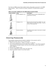
... (POST) runs, the BIOS displays the Maintenance Menu. Use this menu to normal mode. 1. Turn off all peripheral devices connected to be done in the computer and the configuration jumper block is set to clear passwords. Place the jumper on page 25. 2. Clearing Passwords This procedure assumes that the board is installed in the BIOS Setup program. Jumper Settings for the BIOS Setup Program Modes Jumper Setting Mode Normal (default) (1-2) Description The BIOS uses the current configuration and passwords for the BIOS Setup program modes. Disconnect the computer's power...
... (POST) runs, the BIOS displays the Maintenance Menu. Use this menu to normal mode. 1. Turn off all peripheral devices connected to be done in the computer and the configuration jumper block is set to clear passwords. Place the jumper on page 25. 2. Clearing Passwords This procedure assumes that the board is installed in the BIOS Setup program. Jumper Settings for the BIOS Setup Program Modes Jumper Setting Mode Normal (default) (1-2) Description The BIOS uses the current configuration and passwords for the BIOS Setup program modes. Disconnect the computer's power...
English Product Guide
Page 59
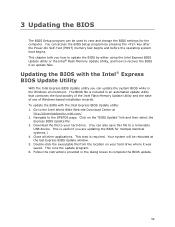
... this file to a removable USB device. The BIOS file is included in the Windows environment. To update the BIOS with the Intel® Express BIOS Update Utility With the Intel Express BIOS Update utility you how to update the BIOS by pressing the key after the Power-On Self-Test (POST) memory test begins and before the operating system boot begins. Go to recover the BIOS if an update fails. This step is useful if you are updating the BIOS for...
... this file to a removable USB device. The BIOS file is included in the Windows environment. To update the BIOS with the Intel® Express BIOS Update Utility With the Intel Express BIOS Update utility you how to update the BIOS by pressing the key after the Power-On Self-Test (POST) memory test begins and before the operating system boot begins. Go to recover the BIOS if an update fails. This step is useful if you are updating the BIOS for...


