
Product Guide
Page 3
... suitability of this manual: CAUTION Cautions warn the user about how to prevent damage to hardware or loss of product features 2 Installing and Replacing Desktop Board Components: instructions on how to install the Desktop Board and other hardware components 3 Updating the BIOS: instructions on how to important information. NOTE Notes call attention to update the BIOS 4 Configuring for RAID Using Intel® Matrix Storage Technology: information about configuring your system for other...
... suitability of this manual: CAUTION Cautions warn the user about how to prevent damage to hardware or loss of product features 2 Installing and Replacing Desktop Board Components: instructions on how to install the Desktop Board and other hardware components 3 Updating the BIOS: instructions on how to important information. NOTE Notes call attention to update the BIOS 4 Configuring for RAID Using Intel® Matrix Storage Technology: information about configuring your system for other...

Product Guide
Page 5
... Systems 11 Desktop Board Components 12 Processor ...14 Main Memory...15 Intel® P55 Express Chipset 16 Audio Subsystem 16 LAN Subsystem 16 USB 2.0 Support 17 Serial ATA Support 17 Legacy I/O ...19 Expandability...19 BIOS ...19 Serial ATA Auto Configuration 19 PCI Express* Auto Configuration 19 Security Passwords 20 Hardware Management 20 Hardware Monitoring and Fan Speed Control 20 Intel® Precision Cooling Technology 20 Chassis Intrusion 21 Power Management 21 Software Support 21 ACPI 21 Hardware Support 21 Power Connectors 21 Fan Headers 22 LAN Wake Capabilities...
... Systems 11 Desktop Board Components 12 Processor ...14 Main Memory...15 Intel® P55 Express Chipset 16 Audio Subsystem 16 LAN Subsystem 16 USB 2.0 Support 17 Serial ATA Support 17 Legacy I/O ...19 Expandability...19 BIOS ...19 Serial ATA Auto Configuration 19 PCI Express* Auto Configuration 19 Security Passwords 20 Hardware Management 20 Hardware Monitoring and Fan Speed Control 20 Intel® Precision Cooling Technology 20 Chassis Intrusion 21 Power Management 21 Software Support 21 ACPI 21 Hardware Support 21 Power Connectors 21 Fan Headers 22 LAN Wake Capabilities...

Product Guide
Page 6
...Express x16 Graphics Card 44 Installing Linked PCI Express Graphics Cards 45 Connecting the Serial ATA (SATA) Cables 47 Connecting to the Internal Headers 48 S/PDIF Header 49 Front Panel Intel HD Audio Header 49 Consumer IR (CIR) Headers 49 Front Panel Header 50 Alternate Front Panel Power LED Header 51 USB 2.0 Headers 51 IEEE 1394a Header 52 Chassis Intrusion Header 52 Connecting to the Audio System 53 Connecting Chassis Fan and Power Supply Cables 54 Connecting Chassis Fan Cables 54 Connecting Power Supply Cables 55 Setting the BIOS Configuration Jumper 56 Clearing Passwords...
...Express x16 Graphics Card 44 Installing Linked PCI Express Graphics Cards 45 Connecting the Serial ATA (SATA) Cables 47 Connecting to the Internal Headers 48 S/PDIF Header 49 Front Panel Intel HD Audio Header 49 Consumer IR (CIR) Headers 49 Front Panel Header 50 Alternate Front Panel Power LED Header 51 USB 2.0 Headers 51 IEEE 1394a Header 52 Chassis Intrusion Header 52 Connecting to the Audio System 53 Connecting Chassis Fan and Power Supply Cables 54 Connecting Chassis Fan Cables 54 Connecting Power Supply Cables 55 Setting the BIOS Configuration Jumper 56 Clearing Passwords...

Product Guide
Page 7
... 5. Example Dual Channel Memory Configuration with Four DIMMs 40 20. Example Dual Channel Memory Configuration with Two DIMMs 39 19. Lift the Load Plate 34 12. Example Dual Channel Memory Configuration with Three DIMMs 40 21. Removing a PCI Express x16 Graphics Card 45 25. SATA Drive Activity LED 18 4. Connecting the Serial ATA Cables 47 27. LAN Connector LEDs 17 3. Unlatch the Socket Lever 33 11. Lower the Load Plate 37 16. Internal Headers 48 vii Connecting the Processor Fan Heat Sink Power Cable to BIOS Button 27 8. Installing...
... 5. Example Dual Channel Memory Configuration with Four DIMMs 40 20. Example Dual Channel Memory Configuration with Two DIMMs 39 19. Lift the Load Plate 34 12. Example Dual Channel Memory Configuration with Three DIMMs 40 21. Removing a PCI Express x16 Graphics Card 45 25. SATA Drive Activity LED 18 4. Connecting the Serial ATA Cables 47 27. LAN Connector LEDs 17 3. Unlatch the Socket Lever 33 11. Lower the Load Plate 37 16. Internal Headers 48 vii Connecting the Processor Fan Heat Sink Power Cable to BIOS Button 27 8. Installing...

Product Guide
Page 8
... 7. BIOS Error Messages 72 17. Intel Desktop Board DP55WG Product Guide 28. Intel Desktop Board DP55WG China RoHS Material Self Declaration Table 85 Tables 1. Intel Desktop Board DP55WG Components 13 3. Chassis Intrusion Header Signal Names 52 13. Lead-Free Second Level Interconnect Marks 83 20. Location of the BIOS Configuration Jumper Block 56 32. Jumper Settings for the BIOS Setup Program Modes 57 14. Removing the Battery 63 33. Location of the Chassis Fan Headers 54 30. USB 2.0 Header Signal Names 51 11. Back Panel Audio Connectors 53...
... 7. BIOS Error Messages 72 17. Intel Desktop Board DP55WG Product Guide 28. Intel Desktop Board DP55WG China RoHS Material Self Declaration Table 85 Tables 1. Intel Desktop Board DP55WG Components 13 3. Chassis Intrusion Header Signal Names 52 13. Lead-Free Second Level Interconnect Marks 83 20. Location of the BIOS Configuration Jumper Block 56 32. Jumper Settings for the BIOS Setup Program Modes 57 14. Removing the Battery 63 33. Location of the Chassis Fan Headers 54 30. USB 2.0 Header Signal Names 51 11. Back Panel Audio Connectors 53...
Product Guide
Page 9
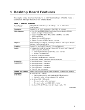
... header • Six Serial ATA (SATA) channels (3.0 Gb/s) via the PCH continued 9 Table 1. 1 Desktop Board Features This chapter briefly describes the features of the Intel P55 Express Chipset Platform Controller Hub (PCH) Graphics Audio Expansion Capabilities Support for multiple PCI Express* 2.0 graphics cards • Independent multi-streaming 8-channel (7.1) audio and 2-channel audio subsystem, featuring: ― Intel® High Definition (Intel® HD) Audio interface ― Realtek* ALC889 codec • HD Audio front panel header • Onboard 4-pin S/PDIF out connector...
... header • Six Serial ATA (SATA) channels (3.0 Gb/s) via the PCH continued 9 Table 1. 1 Desktop Board Features This chapter briefly describes the features of the Intel P55 Express Chipset Platform Controller Hub (PCH) Graphics Audio Expansion Capabilities Support for multiple PCI Express* 2.0 graphics cards • Independent multi-streaming 8-channel (7.1) audio and 2-channel audio subsystem, featuring: ― Intel® High Definition (Intel® HD) Audio interface ― Realtek* ALC889 codec • HD Audio front panel header • Onboard 4-pin S/PDIF out connector...
Product Guide
Page 13
... DIMM 1 sockets Onboard power button Standby power indicator LED Main power connector (2 x 12 pin) SATA drive activity LED Front panel header Back panel CIR transmitter (output) header Front panel CIR receiver (input) header Alternate front panel power LED header Front chassis fan header USB 2.0 headers (2) IEEE 1394a header BIOS configuration jumper block Serial ATA connectors Chassis intrusion header USB 2.0 header Speaker Auxiliary PCI Express graphics power connector (SATA-style) 13 x16 compatible) PCI bus connector PCI Express 2.0 x8 connector (x8 electrical; Intel Desktop Board DP55WG...
... DIMM 1 sockets Onboard power button Standby power indicator LED Main power connector (2 x 12 pin) SATA drive activity LED Front panel header Back panel CIR transmitter (output) header Front panel CIR receiver (input) header Alternate front panel power LED header Front chassis fan header USB 2.0 headers (2) IEEE 1394a header BIOS configuration jumper block Serial ATA connectors Chassis intrusion header USB 2.0 header Speaker Auxiliary PCI Express graphics power connector (SATA-style) 13 x16 compatible) PCI bus connector PCI Express 2.0 x8 connector (x8 electrical; Intel Desktop Board DP55WG...

Product Guide
Page 18
... Windows 7 include the necessary RAID drivers for both AHCI and RAID without the need to your Microsoft Windows XP documentation for more information about installing drivers during Microsoft Windows XP installation, you must press the F6 key to use supported onboard RAID features, you must first enable RAID in the BIOS. data mirroring • RAID 0+1 (or RAID 10) - Refer to install separate RAID drivers using the F6 key. 18 SATA Drive Activity LED The six onboard SATA channels support the following Intel Matrix Storage Technology RAID...
... Windows 7 include the necessary RAID drivers for both AHCI and RAID without the need to your Microsoft Windows XP documentation for more information about installing drivers during Microsoft Windows XP installation, you must press the F6 key to use supported onboard RAID features, you must first enable RAID in the BIOS. data mirroring • RAID 0+1 (or RAID 10) - Refer to install separate RAID drivers using the F6 key. 18 SATA Drive Activity LED The six onboard SATA channels support the following Intel Matrix Storage Technology RAID...

Product Guide
Page 19
x16 compatible) • Two PCI Express 2.0 x1 ports • Two PCI bus connectors BIOS The BIOS provides the Power-On Self-Test (POST), the BIOS Setup program, and the PCI/PCI Express and SATA auto-configuration utilities. You do not need to run the BIOS Setup program after you install a PCI Express add-in card in your computer. You can be updated by specifying manual configuration in the BIOS Setup program. Desktop Board Features Legacy I/O Intel Desktop Board DP55WG includes an I /O features: • Consumer Infrared (CIR) support • Low pin count...
x16 compatible) • Two PCI Express 2.0 x1 ports • Two PCI bus connectors BIOS The BIOS provides the Power-On Self-Test (POST), the BIOS Setup program, and the PCI/PCI Express and SATA auto-configuration utilities. You do not need to run the BIOS Setup program after you install a PCI Express add-in card in your computer. You can be updated by specifying manual configuration in the BIOS Setup program. Desktop Board Features Legacy I/O Intel Desktop Board DP55WG includes an I /O features: • Consumer Infrared (CIR) support • Low pin count...

Product Guide
Page 21
... power supplies can turn off ). The security feature uses a mechanical switch on the chassis that can be connected to the power state it was in the BIOS Setup program's Boot menu. When an ACPI-enabled computer receives the correct command, the power supply removes all non-standby voltages. When resuming from Consumer IR Software Support ACPI ACPI gives the operating system direct control over the power management and Plug and Play functions of ACPI with the Desktop Board...
... power supplies can turn off ). The security feature uses a mechanical switch on the chassis that can be connected to the power state it was in the BIOS Setup program's Boot menu. When an ACPI-enabled computer receives the correct command, the power supply removes all non-standby voltages. When resuming from Consumer IR Software Support ACPI ACPI gives the operating system direct control over the power management and Plug and Play functions of ACPI with the Desktop Board...

Product Guide
Page 22
... . The Desktop Board has a 4-pin processor fan header and two 4-pin chassis fan headers. LAN Wake Capabilities CAUTION For LAN wake capabilities, the 5 V standby line for the power supply must be able to provide enough standby current to provide adequate standby current when using this Desktop Board must be capable of delivering adequate +5 V standby current. Failure to support the standard Instantly Available (ACPI S3 sleep state) configuration. When signaled by the LED turning amber. Power supplies used with this...
... . The Desktop Board has a 4-pin processor fan header and two 4-pin chassis fan headers. LAN Wake Capabilities CAUTION For LAN wake capabilities, the 5 V standby line for the power supply must be able to provide enough standby current to provide adequate standby current when using this Desktop Board must be capable of delivering adequate +5 V standby current. Failure to support the standard Instantly Available (ACPI S3 sleep state) configuration. When signaled by the LED turning amber. Power supplies used with this...
Product Guide
Page 29
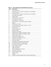
...8226; Connect chassis fan and power supply cables • Set the BIOS configuration jumper • Clear passwords • Replace the battery Before You Begin CAUTIONS The procedures in this chapter only at an ESD workstation using and modifying electronic equipment. 2 Installing and Replacing Desktop Board Components This chapter tells you how to: • Install the I/O shield • Install and remove the Desktop Board • Install and remove a processor • Install and remove memory • Install and remove a PCI Express x16 graphics card • Connect the Serial ATA...
...8226; Connect chassis fan and power supply cables • Set the BIOS configuration jumper • Clear passwords • Replace the battery Before You Begin CAUTIONS The procedures in this chapter only at an ESD workstation using and modifying electronic equipment. 2 Installing and Replacing Desktop Board Components This chapter tells you how to: • Install the I/O shield • Install and remove the Desktop Board • Install and remove a processor • Install and remove memory • Install and remove a PCI Express x16 graphics card • Connect the Serial ATA...

Product Guide
Page 42
... peripheral devices connected to the open position. 6. Remove the computer's cover and locate the DIMM sockets (see Removing a PCI Express x16 Graphics Card on the top edge of the DIMM into place. Figure 22. If a full length PCI Express graphics card is inserted, push down on page 44) to gain access to the DIMM sockets. 5. Position the DIMM above the socket. Intel Desktop Board DP55WG Product Guide NOTE For best memory performance, install memory in...
... peripheral devices connected to the open position. 6. Remove the computer's cover and locate the DIMM sockets (see Removing a PCI Express x16 Graphics Card on the top edge of the DIMM into place. Figure 22. If a full length PCI Express graphics card is inserted, push down on page 44) to gain access to the DIMM sockets. 5. Position the DIMM above the socket. Intel Desktop Board DP55WG Product Guide NOTE For best memory performance, install memory in...
Product Guide
Page 43
... connector pins. Replace the computer's cover and reconnect the AC power cord. Reinstall the PCI Express graphics card (see Installing a PCI Express x16 Graphics Card on page 29. 2. Turn off the computer. 3. The DIMM pops out of the socket. 7. Installing and Replacing Desktop Board Components 10. Reinstall the PCI Express graphics card (see Removing a PCI Express x16 Graphics Card on the system. Remove the computer's cover. 5. Hold the DIMM by the PCI Express card. If the card is installed in the PCI Express x16 connector, remove the card (see Installing a PCI Express...
... connector pins. Replace the computer's cover and reconnect the AC power cord. Reinstall the PCI Express graphics card (see Installing a PCI Express x16 Graphics Card on page 29. 2. Turn off the computer. 3. The DIMM pops out of the socket. 7. Installing and Replacing Desktop Board Components 10. Reinstall the PCI Express graphics card (see Removing a PCI Express x16 Graphics Card on the system. Remove the computer's cover. 5. Hold the DIMM by the PCI Express card. If the card is installed in the PCI Express x16 connector, remove the card (see Installing a PCI Express...

Product Guide
Page 45
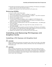
... mechanism pin on page 29. 2. Secure the card's metal bracket to install linked PCI Express graphics cards such as shown. 45 You can use two identical SLI-ready graphics cards that allows you use the connector included with a screw (Figure 25, B). 5. Make sure you to the chassis back panel with the Desktop Board to connect the two graphics cards together. Removing a PCI Express x16 Graphics Card Installing Linked PCI Express Graphics Cards The Desktop Board supports technology that are NVIDIA certified and the latest graphics driver.
... mechanism pin on page 29. 2. Secure the card's metal bracket to install linked PCI Express graphics cards such as shown. 45 You can use two identical SLI-ready graphics cards that allows you use the connector included with a screw (Figure 25, B). 5. Make sure you to the chassis back panel with the Desktop Board to connect the two graphics cards together. Removing a PCI Express x16 Graphics Card Installing Linked PCI Express Graphics Cards The Desktop Board supports technology that are NVIDIA certified and the latest graphics driver.

Product Guide
Page 49
... Audio header. Table 4. Table 5 shows the pin assignments and signal names for the S/PDIF connector. Press at boot to enter the system BIOS, and go to Advanced > Peripheral Configuration > Enhanced Consumer IR, and set this option to speak the infrared communication language of other user remotes. The learning input is a high-pass input which the computer can use to "learn" to Enabled. 49 Installing and Replacing Desktop Board...
... Audio header. Table 4. Table 5 shows the pin assignments and signal names for the S/PDIF connector. Press at boot to enter the system BIOS, and go to Advanced > Peripheral Configuration > Enhanced Consumer IR, and set this option to speak the infrared communication language of other user remotes. The learning input is a high-pass input which the computer can use to "learn" to Enabled. 49 Installing and Replacing Desktop Board...

Product Guide
Page 57
..., turn on pins 2-3 as shown below. 6. Disconnect the computer's power cord from the AC power source (wall outlet or power adapter). 3. The computer starts the Setup program. Remove the computer cover. 4. Clearing Passwords This procedure assumes that the board is installed in the event of a failed BIOS update. Turn off the computer. Setup displays the Maintenance menu. 57 Jumper Settings for the BIOS Setup Program Modes Jumper Setting Mode Normal (default) (1-2) Description The BIOS uses the current configuration and passwords for booting. Recovery...
..., turn on pins 2-3 as shown below. 6. Disconnect the computer's power cord from the AC power source (wall outlet or power adapter). 3. The computer starts the Setup program. Remove the computer cover. 4. Clearing Passwords This procedure assumes that the board is installed in the event of a failed BIOS update. Turn off the computer. Setup displays the Maintenance menu. 57 Jumper Settings for the BIOS Setup Program Modes Jumper Setting Mode Normal (default) (1-2) Description The BIOS uses the current configuration and passwords for booting. Recovery...

Product Guide
Page 66
... BIOS configuration jumper. Intel Desktop Board DP55WG Product Guide Updating the BIOS with the ISO Image BIOS Update File The ISO Image BIOS update allows for the update of an Intel® Desktop Board BIOS to the latest production release regardless of uncompressing and writing the ISO image file to CD. The Iflash BIOS update file contains: • New BIOS file (including the Intel® Management Engine Firmware Image) • Intel® Integrator Toolkit Configuration File (optional) • Intel Flash Memory Update Utility You can update to a new version...
... BIOS configuration jumper. Intel Desktop Board DP55WG Product Guide Updating the BIOS with the ISO Image BIOS Update File The ISO Image BIOS update allows for the update of an Intel® Desktop Board BIOS to the latest production release regardless of uncompressing and writing the ISO image file to CD. The Iflash BIOS update file contains: • New BIOS file (including the Intel® Management Engine Firmware Image) • Intel® Integrator Toolkit Configuration File (optional) • Intel Flash Memory Update Utility You can update to a new version...

Product Guide
Page 70
... to update to manage the RAID configuration. Install the Intel Matrix Storage Console software via the Intel Express Installer CD included with your Desktop Board or after downloading it from the Internet at http://support.intel.com/support/motherboards/desktop/. At the beginning of Windows Setup, press to upgrade from the Windows installation CD. 2. Install the Intel® SATA RAID Controller driver. 3. Intel Desktop Board DP55WG Product Guide Loading the Intel Matrix Storage Technology RAID Drivers and Software (Required for information on supported USB floppy disk drives.
... to update to manage the RAID configuration. Install the Intel Matrix Storage Console software via the Intel Express Installer CD included with your Desktop Board or after downloading it from the Internet at http://support.intel.com/support/motherboards/desktop/. At the beginning of Windows Setup, press to upgrade from the Windows installation CD. 2. Install the Intel® SATA RAID Controller driver. 3. Intel Desktop Board DP55WG Product Guide Loading the Intel Matrix Storage Technology RAID Drivers and Software (Required for information on supported USB floppy disk drives.

Product Guide
Page 71
A Error Messages and Indicators Intel Desktop Board DP55WG reports POST errors in progress Off when the update begins, then on the monitor • By displaying diagnostic progress codes (POST codes) BIOS Error Codes Whenever a recoverable error occurs during POST, the BIOS causes the board's speaker to beep and the front panel power LED to blink an error message indicating the problem (see Table 14). Table 14. Memory error On-off (0.5 seconds each ) two times, then 3.0 second pause (off), entire pattern...
A Error Messages and Indicators Intel Desktop Board DP55WG reports POST errors in progress Off when the update begins, then on the monitor • By displaying diagnostic progress codes (POST codes) BIOS Error Codes Whenever a recoverable error occurs during POST, the BIOS causes the board's speaker to beep and the front panel power LED to blink an error message indicating the problem (see Table 14). Table 14. Memory error On-off (0.5 seconds each ) two times, then 3.0 second pause (off), entire pattern...


