
Product Guide
Page 3
... Intended Applications All Intel Desktop Boards are arranged as follows: 1 Desktop Board Features: a summary of product features 2 Installing and Replacing Desktop Board Components: instructions on how to install the Desktop Board and other hardware components 3 Updating the BIOS: instructions on how to update the BIOS 4 Configuring for RAID Using Intel® Matrix Storage...industrial, alarm systems, test equipment, etc. iii The suitability of data. Intended Audience The Product Guide is not intended for Intel® Desktop Board DP55WG. may not be supported without further evaluation by...
... Intended Applications All Intel Desktop Boards are arranged as follows: 1 Desktop Board Features: a summary of product features 2 Installing and Replacing Desktop Board Components: instructions on how to install the Desktop Board and other hardware components 3 Updating the BIOS: instructions on how to update the BIOS 4 Configuring for RAID Using Intel® Matrix Storage...industrial, alarm systems, test equipment, etc. iii The suitability of data. Intended Audience The Product Guide is not intended for Intel® Desktop Board DP55WG. may not be supported without further evaluation by...

Product Guide
Page 5
... Features Supported Operating Systems 11 Desktop Board Components 12 Processor ...14 Main Memory...15 Intel® P55 Express Chipset 16 Audio Subsystem 16 LAN Subsystem 16 USB 2.0 Support 17 Serial ATA Support 17 Legacy I/O ...19 Expandability...19 BIOS ...19 Serial ATA Auto Configuration 19 PCI Express* Auto Configuration 19 Security Passwords 20 Hardware Management...
... Features Supported Operating Systems 11 Desktop Board Components 12 Processor ...14 Main Memory...15 Intel® P55 Express Chipset 16 Audio Subsystem 16 LAN Subsystem 16 USB 2.0 Support 17 Serial ATA Support 17 Legacy I/O ...19 Expandability...19 BIOS ...19 Serial ATA Auto Configuration 19 PCI Express* Auto Configuration 19 Security Passwords 20 Hardware Management...

Product Guide
Page 6
Intel Desktop Board DP55WG Product Guide Installing and Removing the Desktop Board 32 Installing and Removing a Processor 33 Installing a Processor 33 Installing the Processor Fan Heat Sink 38 Connecting the Processor Fan Heat Sink Cable 38... Chassis Fan Cables 54 Connecting Power Supply Cables 55 Setting the BIOS Configuration Jumper 56 Clearing Passwords 57 Replacing the Battery 58 3 Updating the BIOS Updating the BIOS with the Intel® Express BIOS Update Utility 65 Updating the BIOS with the ISO Image BIOS Update File or the Iflash Memory Update Utility 66 Obtaining the...
Intel Desktop Board DP55WG Product Guide Installing and Removing the Desktop Board 32 Installing and Removing a Processor 33 Installing a Processor 33 Installing the Processor Fan Heat Sink 38 Connecting the Processor Fan Heat Sink Cable 38... Chassis Fan Cables 54 Connecting Power Supply Cables 55 Setting the BIOS Configuration Jumper 56 Clearing Passwords 57 Replacing the Battery 58 3 Updating the BIOS Updating the BIOS with the Intel® Express BIOS Update Utility 65 Updating the BIOS with the ISO Image BIOS Update File or the Iflash Memory Update Utility 66 Obtaining the...

Product Guide
Page 7
... 88 Board-Level Certification Markings 88 Chassis and Component Certifications 89 Figures 1. Connecting the Processor Fan Heat Sink Power Cable to BIOS Button 27 8. SATA Drive Activity LED 18 4. Intel Desktop Board DP55WG Mounting Screw Hole Locations 32 10. Lower the Load Plate 37 16. Installing the I/O Shield 31 9. Example Dual Channel Memory Configuration... 45 25. Connecting the Serial ATA Cables 47 27. Example Dual Channel Memory Configuration with Two DIMMs 39 19. Remove the Socket Cover 35 13. Intel Desktop Board DP55WG Components 12 2.
... 88 Board-Level Certification Markings 88 Chassis and Component Certifications 89 Figures 1. Connecting the Processor Fan Heat Sink Power Cable to BIOS Button 27 8. SATA Drive Activity LED 18 4. Intel Desktop Board DP55WG Mounting Screw Hole Locations 32 10. Lower the Load Plate 37 16. Installing the I/O Shield 31 9. Example Dual Channel Memory Configuration... 45 25. Connecting the Serial ATA Cables 47 27. Example Dual Channel Memory Configuration with Two DIMMs 39 19. Remove the Socket Cover 35 13. Intel Desktop Board DP55WG Components 12 2.

Product Guide
Page 8
...56 32. Connecting Power Supply Cables 55 31. LAN Connector LEDs 17 4. USB 2.0 Header Signal Names 51 11. BIOS Error Messages 72 17. Intel Desktop Board DP55WG Product Guide 28. Back Panel Audio Connectors 53 29. Port 80h POST Codes 74 18. Product Certification Markings 88 viii...Chassis Fan Headers 54 30. Front Panel Header Signal Names 50 9. IEEE 1394a Header Signal Names 52 12. Intel Desktop Board DP55WG Components 13 3. Jumper Settings for the BIOS Setup Program Modes 57 14. Lead-Free Second Level Interconnect Marks 83 20. Location of the POST Code LED...
...56 32. Connecting Power Supply Cables 55 31. LAN Connector LEDs 17 4. USB 2.0 Header Signal Names 51 11. BIOS Error Messages 72 17. Intel Desktop Board DP55WG Product Guide 28. Back Panel Audio Connectors 53 29. Port 80h POST Codes 74 18. Product Certification Markings 88 viii...Chassis Fan Headers 54 30. Front Panel Header Signal Names 50 9. IEEE 1394a Header Signal Names 52 12. Intel Desktop Board DP55WG Components 13 3. Jumper Settings for the BIOS Setup Program Modes 57 14. Lead-Free Second Level Interconnect Marks 83 20. Location of the POST Code LED...

Product Guide
Page 10
Intel Desktop Board DP55WG Product Guide Table 1. Feature Summary (continued) RAID Intel® Matrix Storage Technology for Serial ATA LAN Support Intel 82578DM Gigabit (10/100/1000 Mb/s) Ethernet LAN controller including an RJ-45 back panel connector with integrated status LEDs BIOS • Intel®...Innovation Framework for extensible firmware interface • 16 Mb symmetrical flash memory device • Support for SMBIOS • Intel® Express BIOS Update Power Management • Support for Advanced Configuration and Power Interface (ACPI) • Suspend to RAM (STR)...
Intel Desktop Board DP55WG Product Guide Table 1. Feature Summary (continued) RAID Intel® Matrix Storage Technology for Serial ATA LAN Support Intel 82578DM Gigabit (10/100/1000 Mb/s) Ethernet LAN controller including an RJ-45 back panel connector with integrated status LEDs BIOS • Intel®...Innovation Framework for extensible firmware interface • 16 Mb symmetrical flash memory device • Support for SMBIOS • Intel® Express BIOS Update Power Management • Support for Advanced Configuration and Power Interface (ACPI) • Suspend to RAM (STR)...
Product Guide
Page 13
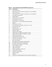
Intel Desktop Board DP55WG Components Label A B C D E F G H I J K L M N O P Q R S T U V W X Y Z AA BB CC DD EE FF GG HH II JJ KK Description PCI bus connector PCI Express 2.0 x4 connector (x4 electrical; x16 compatible) PCI bus connector PCI Express 2.0 x8 connector (x8 electrical; Desktop... Board Features Table 2. x16 compatible) Front panel audio header S/PDIF header PCI Express 2.0 x1 connector Rear chassis fan header PCI Express 2.0 x1 connector PCI Express 2.0 x16 connector (x8/x16 electrical) Battery Back panel connectors 12 V processor core... BIOS configuration jumper block Serial ...
Intel Desktop Board DP55WG Components Label A B C D E F G H I J K L M N O P Q R S T U V W X Y Z AA BB CC DD EE FF GG HH II JJ KK Description PCI bus connector PCI Express 2.0 x4 connector (x4 electrical; x16 compatible) PCI bus connector PCI Express 2.0 x8 connector (x8 electrical; Desktop... Board Features Table 2. x16 compatible) Front panel audio header S/PDIF header PCI Express 2.0 x1 connector Rear chassis fan header PCI Express 2.0 x1 connector PCI Express 2.0 x16 connector (x8/x16 electrical) Battery Back panel connectors 12 V processor core... BIOS configuration jumper block Serial ...

Product Guide
Page 14
... may result in the LGA1156 package. Intel Desktop Board DP55WG Product Guide Online Support For more information on supported processors for Intel Desktop Board DP55WG http://www.intel.com/products/motherboard/DP55WG /index.htm • Supported processors http://processormatch.intel.com • Chipset information http://www.intel.com/products/desktop/chipsets/inde x.htm • BIOS and driver updates http://downloadcenter.intel.com/ • Integration information...
... may result in the LGA1156 package. Intel Desktop Board DP55WG Product Guide Online Support For more information on supported processors for Intel Desktop Board DP55WG http://www.intel.com/products/motherboard/DP55WG /index.htm • Supported processors http://processormatch.intel.com • Chipset information http://www.intel.com/products/desktop/chipsets/inde x.htm • BIOS and driver updates http://downloadcenter.intel.com/ • Integration information...
Product Guide
Page 15
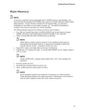
... Support for normal operation. Desktop Board Features Main Memory NOTE To be fully compliant with all applicable Intel ® SDRAM memory specifications, the board should be populated with a voltage rating higher than 4 GB because of BIOS and manual memory tuning. The BIOS will see a notification to... this effect on this desktop board requires compatible XMP-...
... Support for normal operation. Desktop Board Features Main Memory NOTE To be fully compliant with all applicable Intel ® SDRAM memory specifications, the board should be populated with a voltage rating higher than 4 GB because of BIOS and manual memory tuning. The BIOS will see a notification to... this effect on this desktop board requires compatible XMP-...

Product Guide
Page 17
...link is established LAN activity is occurring 10 Mb/s data rate 100 Mb/s data rate 1000 Mb/s data rate USB 2.0 Support The Desktop Board provides 14 USB 2.0 ports (eight ports routed to back panel connectors and six ports routed to USB 1.1 operation. This may ... with USB 1.1 devices. Disabling Hi-Speed USB in Figure 3. 17 Serial ATA Support Intel Desktop Board DP55WG supports six onboard 3.0 Gb/s Serial ATA (SATA) channels via the PCH. The Desktop Board includes a SATA drive activity indicator (a blue LED) shown in the BIOS reverts all USB 2.0 ports to three onboard headers...
...link is established LAN activity is occurring 10 Mb/s data rate 100 Mb/s data rate 1000 Mb/s data rate USB 2.0 Support The Desktop Board provides 14 USB 2.0 ports (eight ports routed to back panel connectors and six ports routed to USB 1.1 operation. This may ... with USB 1.1 devices. Disabling Hi-Speed USB in Figure 3. 17 Serial ATA Support Intel Desktop Board DP55WG supports six onboard 3.0 Gb/s Serial ATA (SATA) channels via the PCH. The Desktop Board includes a SATA drive activity indicator (a blue LED) shown in the BIOS reverts all USB 2.0 ports to three onboard headers...

Product Guide
Page 18
... both AHCI and RAID without the need to install separate RAID drivers using the F6 key. 18 Intel Desktop Board DP55WG Product Guide Figure 3. SATA Drive Activity LED The six onboard SATA channels support the following Intel Matrix Storage Technology RAID (Redundant Array of Independent Drives) levels: • RAID 0 - Both Microsoft Windows Vista and... drivers during Microsoft Windows XP installation, you must press the F6 key to use supported onboard RAID features, you must first enable RAID in the BIOS. distributed parity NOTE In order to install the RAID drivers.
... both AHCI and RAID without the need to install separate RAID drivers using the F6 key. 18 Intel Desktop Board DP55WG Product Guide Figure 3. SATA Drive Activity LED The six onboard SATA channels support the following Intel Matrix Storage Technology RAID (Redundant Array of Independent Drives) levels: • RAID 0 - Both Microsoft Windows Vista and... drivers during Microsoft Windows XP installation, you must press the F6 key to use supported onboard RAID features, you must first enable RAID in the BIOS. distributed parity NOTE In order to install the RAID drivers.

Product Guide
Page 19
... PCI Express add-in your computer. The BIOS is stored in the BIOS Setup program. You can be updated by specifying manual configuration in a Serial Peripheral Interface (SPI) Flash device. Desktop Board Features Legacy I/O Intel Desktop Board DP55WG includes an I /O features: • ... (LPC) interface • Intelligent power management, including a programmable wake up event interface • PCI power management support Expandability Intel Desktop Board DP55WG provides the following expansion capability: • One PCI Express 2.0 x16 port (x8/x16 electrical) • One PCI Express...
... PCI Express add-in your computer. The BIOS is stored in the BIOS Setup program. You can be updated by specifying manual configuration in a Serial Peripheral Interface (SPI) Flash device. Desktop Board Features Legacy I/O Intel Desktop Board DP55WG includes an I /O features: • ... (LPC) interface • Intelligent power management, including a programmable wake up event interface • PCI power management support Expandability Intel Desktop Board DP55WG provides the following expansion capability: • One PCI Express 2.0 x16 port (x8/x16 electrical) • One PCI Express...
Product Guide
Page 20
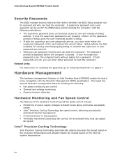
Intel Desktop Board DP55WG Product Guide Security Passwords The BIOS includes security features that can enter either the supervisor password or ... can boot the computer. If only the supervisor password is set , you can adjust fan speed Intel® Precision Cooling Technology Intel Precision Cooling Technology automatically adjusts processor fan speed based on the processor temperature and adjusts chassis fan speeds...is booted. Setup options are set , pressing at the password prompt of Intel Desktop Board DP55WG enable the board to detect levels above and below acceptable values •...
Intel Desktop Board DP55WG Product Guide Security Passwords The BIOS includes security features that can enter either the supervisor password or ... can boot the computer. If only the supervisor password is set , you can adjust fan speed Intel® Precision Cooling Technology Intel Precision Cooling Technology automatically adjusts processor fan speed based on the processor temperature and adjusts chassis fan speeds...is booted. Setup options are set , pressing at the password prompt of Intel Desktop Board DP55WG enable the board to detect levels above and below acceptable values •...

Product Guide
Page 21
... on or off). The computer's response can be set by using the Last Power State feature in before power was in the BIOS Setup program's Boot menu. Power Management Power management is implemented at several levels, including software support through system control. When resuming...standby voltages. See Figure 30 on the chassis that can be connected to the power state it was interrupted (either on the Desktop Board. Desktop Board Features Chassis Intrusion The board supports a chassis security feature that provides full ACPI support. The security feature uses a mechanical ...
... on or off). The computer's response can be set by using the Last Power State feature in before power was in the BIOS Setup program's Boot menu. Power Management Power management is implemented at several levels, including software support through system control. When resuming...standby voltages. See Figure 30 on the chassis that can be connected to the power state it was interrupted (either on the Desktop Board. Desktop Board Features Chassis Intrusion The board supports a chassis security feature that provides full ACPI support. The security feature uses a mechanical ...
Product Guide
Page 27
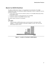
...factory defaults, use the key once BIOS setup mode is activated. Desktop Board Features Back to BIOS Button The Back to BIOS button (Figure 7, A) duplicates the functionality of the Back to BIOS Button 27 Location of the BIOS configuration jumper (see Setting the BIOS Configuration Jumper on page 56) with... the following exceptions: • It can only be used to force the board to power on to the BIOS Maintenance Menu using default values. ...
...factory defaults, use the key once BIOS setup mode is activated. Desktop Board Features Back to BIOS Button The Back to BIOS button (Figure 7, A) duplicates the functionality of the Back to BIOS Button 27 Location of the BIOS configuration jumper (see Setting the BIOS Configuration Jumper on page 56) with... the following exceptions: • It can only be used to force the board to power on to the BIOS Maintenance Menu using default values. ...
Product Guide
Page 29
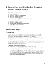
... result in personal injury or equipment damage. 2 Installing and Replacing Desktop Board Components This chapter tells you how to: • Install the I/O shield • Install and remove the Desktop Board • Install and remove a processor • Install and... remove memory • Install and remove a PCI Express x16 graphics card • Connect the Serial ATA cables • Connect to the internal headers • Connect to the audio system • Connect chassis fan and power supply cables • Set the BIOS...
... result in personal injury or equipment damage. 2 Installing and Replacing Desktop Board Components This chapter tells you how to: • Install the I/O shield • Install and remove the Desktop Board • Install and remove a processor • Install and... remove memory • Install and remove a PCI Express x16 graphics card • Connect the Serial ATA cables • Connect to the internal headers • Connect to the audio system • Connect chassis fan and power supply cables • Set the BIOS...

Product Guide
Page 49
...BIOS, and go to Advanced > Peripheral Configuration > Enhanced Consumer IR, and set this option to speak the infrared communication language of the front panel Intel HD Audio header. Table 4. S/PDIF Header Signal Names Pin Description 1 Ground 2 S/PDIF Out 3 Key (no pin) 10 SENSE2_RETURN Consumer IR (CIR) Headers The Desktop...Consumer IR option must be enabled in order to emulate "learned" infrared commands in the system BIOS before it can use to "learn" to Enabled. 49 Front Panel Intel HD Audio Header Signal Names Pin Signal Name 1 PORT 1L 3 PORT 1R 5 PORT 2R ...
...BIOS, and go to Advanced > Peripheral Configuration > Enhanced Consumer IR, and set this option to speak the infrared communication language of the front panel Intel HD Audio header. Table 4. S/PDIF Header Signal Names Pin Description 1 Ground 2 S/PDIF Out 3 Key (no pin) 10 SENSE2_RETURN Consumer IR (CIR) Headers The Desktop...Consumer IR option must be enabled in order to emulate "learned" infrared commands in the system BIOS before it can use to "learn" to Enabled. 49 Front Panel Intel HD Audio Header Signal Names Pin Signal Name 1 PORT 1L 3 PORT 1R 5 PORT 2R ...

Product Guide
Page 56
... 12 V processor core voltage power supply cable to the 2 x 12 pin connector (Figure 30, C). 4. Connect the main power supply cable to the 2 x 4 pin connector (Figure 30, A) . 3. Figure 31 shows the location of the BIOS Configuration Jumper Block The three-pin BIOS jumper block enables board...the power on page 29. 2. If additional power is required for the BIOS Setup program modes. 56 Intel Desktop Board DP55WG Product Guide 1. Observe the precautions in "Before You Begin" on may result in the BIOS Setup program. Figure 31. Table 13 shows the jumper settings for graphics...
... 12 V processor core voltage power supply cable to the 2 x 12 pin connector (Figure 30, C). 4. Connect the main power supply cable to the 2 x 4 pin connector (Figure 30, A) . 3. Figure 31 shows the location of the BIOS Configuration Jumper Block The three-pin BIOS jumper block enables board...the power on page 29. 2. If additional power is required for the BIOS Setup program modes. 56 Intel Desktop Board DP55WG Product Guide 1. Observe the precautions in "Before You Begin" on may result in the BIOS Setup program. Figure 31. Table 13 shows the jumper settings for graphics...

Product Guide
Page 57
... the configuration jumper block is set to boot. 7. Installing and Replacing Desktop Board Components Table 13. Jumper Settings for the BIOS Setup Program Modes Jumper Setting Mode Normal (default) (1-2) Description The BIOS uses the current configuration and passwords for booting. Configure (2-3) After the Power.... 57 Find the configuration jumper block (see Figure 31). 5. Replace the cover, plug in the event of a failed BIOS update. Recovery (None) The BIOS recovers data in the computer, turn on the computer, and allow it to normal mode. 1. The computer starts the Setup...
... the configuration jumper block is set to boot. 7. Installing and Replacing Desktop Board Components Table 13. Jumper Settings for the BIOS Setup Program Modes Jumper Setting Mode Normal (default) (1-2) Description The BIOS uses the current configuration and passwords for booting. Configure (2-3) After the Power.... 57 Find the configuration jumper block (see Figure 31). 5. Replace the cover, plug in the event of a failed BIOS update. Recovery (None) The BIOS recovers data in the computer, turn on the computer, and allow it to normal mode. 1. The computer starts the Setup...
Product Guide
Page 58
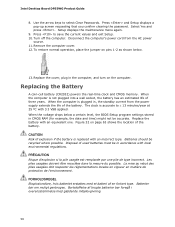
...232;re de protection de l'environnement. Bortskaffelse af brugte batterier bør foregå i overensstemmelse med gældende miljølovgivning. 58 Intel Desktop Board DP55WG Product Guide 8. When the computer is accurate to ± 13 minutes/year at 25 ºC with an incorrect type. FORHOLDSREGEL Eksplosionsfare, ...be recycled where possible. When the voltage drops below . 13. Figure 32 on pins 1-2 as shown below a certain level, the BIOS Setup program settings stored in accordance with an equivalent one. Les piles usagées doivent être recyclées dans la ...
...232;re de protection de l'environnement. Bortskaffelse af brugte batterier bør foregå i overensstemmelse med gældende miljølovgivning. 58 Intel Desktop Board DP55WG Product Guide 8. When the computer is accurate to ± 13 minutes/year at 25 ºC with an incorrect type. FORHOLDSREGEL Eksplosionsfare, ...be recycled where possible. When the voltage drops below . 13. Figure 32 on pins 1-2 as shown below a certain level, the BIOS Setup program settings stored in accordance with an equivalent one. Les piles usagées doivent être recyclées dans la ...


