

Product Specification
Page 6
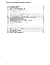
... PCI* Autoconfiguration 64 3.4 System Management BIOS (SMBIOS 65 3.5 Legacy USB Support 66 3.6 BIOS Updates 67 3.6.1 Language Support 67 3.6.2 Custom Splash Screen 67 3.7 BIOS Recovery 68 3.8 Boot Options 68 3.8.1 CD-ROM Boot 68 3.8.2 Network Boot 68 3.8.3 Booting Without Attached Devices 69 3.8.4 Changing the Default Boot Device During POST 69 3.9 Adjusting Boot Speed 69 3.9.1 Peripheral Selection and Configuration 69 3.9.2 BIOS Boot Optimizations 70 3.10 BIOS Security Features 71 4 Error Messages and Beep Codes 4.1 Speaker 73 4.2 BIOS Beep Codes 73 4.3 Front-panel Power LED...
... PCI* Autoconfiguration 64 3.4 System Management BIOS (SMBIOS 65 3.5 Legacy USB Support 66 3.6 BIOS Updates 67 3.6.1 Language Support 67 3.6.2 Custom Splash Screen 67 3.7 BIOS Recovery 68 3.8 Boot Options 68 3.8.1 CD-ROM Boot 68 3.8.2 Network Boot 68 3.8.3 Booting Without Attached Devices 69 3.8.4 Changing the Default Boot Device During POST 69 3.9 Adjusting Boot Speed 69 3.9.1 Peripheral Selection and Configuration 69 3.9.2 BIOS Boot Optimizations 70 3.10 BIOS Security Features 71 4 Error Messages and Beep Codes 4.1 Speaker 73 4.2 BIOS Beep Codes 73 4.3 Front-panel Power LED...

Product Specification
Page 7
...-side Connectors and Headers 46 11. Supported Memory Configurations 16 4. Effects of the BIOS Configuration Jumper Block 55 14. Back Panel Connectors 45 10. Connection Diagram for AC '97 Audio 48 14. Front Panel Audio Header for Front Panel Header 51 12. Processor Core Power Connector 50 vii Power States and Targeted System Power 32 9. Front, Rear, and Processor (4-Pin) Fan Header 49 18. Board Components Shown in Figure 10 47 12. Board Dimensions 57 15. Thermal Sensors and Fan Headers 30 7. Serial Port Header...
...-side Connectors and Headers 46 11. Supported Memory Configurations 16 4. Effects of the BIOS Configuration Jumper Block 55 14. Back Panel Connectors 45 10. Connection Diagram for AC '97 Audio 48 14. Front Panel Audio Header for Front Panel Header 51 12. Processor Core Power Connector 50 vii Power States and Targeted System Power 32 9. Front, Rear, and Processor (4-Pin) Fan Header 49 18. Board Components Shown in Figure 10 47 12. Board Dimensions 57 15. Thermal Sensors and Fan Headers 30 7. Serial Port Header...
Product Specification
Page 8
... 27. Boot Device Menu Options 69 34. BIOS Error Messages 74 37. Typical Port 80h POST Sequence 79 40. Lead-Free Board Markings 86 42. States for Components 60 29. Supervisor and User Password Functions 71 35. Beep Codes 73 36. Product Certification Markings 88 viii Main Power Connector 50 20. Thermal Considerations for a Two-Color Power LED 52 23. Intel Desktop Board DB43LD Technical Product Specification 19. Intel Desktop Board DB43LD Environmental Specifications 61 30. Front Panel Header 51 21...
... 27. Boot Device Menu Options 69 34. BIOS Error Messages 74 37. Typical Port 80h POST Sequence 79 40. Lead-Free Board Markings 86 42. States for Components 60 29. Supervisor and User Password Functions 71 35. Beep Codes 73 36. Product Certification Markings 88 viii Main Power Connector 50 20. Thermal Considerations for a Two-Color Power LED 52 23. Intel Desktop Board DB43LD Technical Product Specification 19. Intel Desktop Board DB43LD Environmental Specifications 61 30. Front Panel Header 51 21...

Product Specification
Page 10
... Controller • Intel® BIOS (resident in the SPI Flash device) • Support for Advanced Configuration and Power Interface (ACPI), Plug and Play, and SMBIOS Instantly Available PC Technology Expansion Capabilities Hardware Monitor Subsystem • Support for PCI* Local Bus Specification Revision 2.3 • Support for PCI Express* Revision 1.0a • Suspend to RAM support • Wake on PCI, PCI Express, PS/2 devices, serial port, front panel, USB ports, and LAN • One PCI Express x16 bus add-in card connector • One PCI Express x1 bus add-in card connector...
... Controller • Intel® BIOS (resident in the SPI Flash device) • Support for Advanced Configuration and Power Interface (ACPI), Plug and Play, and SMBIOS Instantly Available PC Technology Expansion Capabilities Hardware Monitor Subsystem • Support for PCI* Local Bus Specification Revision 2.3 • Support for PCI Express* Revision 1.0a • Suspend to RAM support • Wake on PCI, PCI Express, PS/2 devices, serial port, front panel, USB ports, and LAN • One PCI Express x16 bus add-in card connector • One PCI Express x1 bus add-in card connector...
Product Specification
Page 14
... Intel Desktop Board products, with specific changes including (but not limited to) the following: • No serial port on the back panel • No diskette drive connector • No parallel ATA connector • The serial port header is located near the 2 x 12 power connector and may require a specialized chassis or cabling solution to use 1.3 Online Support To find information about... Intel Desktop Board DB43LD Desktop Board Support Available configurations for the Intel Desktop Board DB43LD Supported processors Chipset information BIOS and driver updates Tested memory Integration...
... Intel Desktop Board products, with specific changes including (but not limited to) the following: • No serial port on the back panel • No diskette drive connector • No parallel ATA connector • The serial port header is located near the 2 x 12 power connector and may require a specialized chassis or cabling solution to use 1.3 Online Support To find information about... Intel Desktop Board DB43LD Desktop Board Support Available configurations for the Intel Desktop Board DB43LD Supported processors Chipset information BIOS and driver updates Tested memory Integration...

Product Specification
Page 16
Intel Desktop Board DB43LD Technical Product Specification 1.5 System Memory The board has two DIMM sockets and supports the following restriction: Double-sided DIMMs with x16 organization are not supported. • 8 GB maximum total system memory using DDR2 800 MHz or DDR2 667 MHz DIMMs; Table 3. Supported Memory Configurations DIMM Type SDRAM Technology Smallest usable DIMM (one x16 Single-sided DIMM) Largest usable DIMM (one x8 Double-sided DIMM...
Intel Desktop Board DB43LD Technical Product Specification 1.5 System Memory The board has two DIMM sockets and supports the following restriction: Double-sided DIMMs with x16 organization are not supported. • 8 GB maximum total system memory using DDR2 800 MHz or DDR2 667 MHz DIMMs; Table 3. Supported Memory Configurations DIMM Type SDRAM Technology Smallest usable DIMM (one x16 Single-sided DIMM) Largest usable DIMM (one x8 Double-sided DIMM...

Product Specification
Page 54
Connection Diagram for high-speed USB devices. Intel Desktop Board DB43LD Technical Product Specification 2.2.2.7 Front Panel USB Headers Figure 12 is a connection diagram for the front panel USB headers. # INTEGRATOR'S NOTES • The +5 V DC power on the USB headers is fused. • Use only a front panel USB connector that conforms to the USB 2.0 specification for Front Panel USB Headers 54 Figure 12.
Connection Diagram for high-speed USB devices. Intel Desktop Board DB43LD Technical Product Specification 2.2.2.7 Front Panel USB Headers Figure 12 is a connection diagram for the front panel USB headers. # INTEGRATOR'S NOTES • The +5 V DC power on the USB headers is fused. • Use only a front panel USB connector that conforms to the USB 2.0 specification for Front Panel USB Headers 54 Figure 12.
Product Specification
Page 63
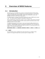
... BIOS Setup program, POST, the PCI auto-configuration utility, LAN EEPROM information, and Plug and Play support. When the BIOS Setup configuration jumper is set to configure mode and the computer is in the BIOS and reports if the two match. The BIOS Setup program can be used to put the board in the Serial Peripheral Interface Flash Memory (SPI Flash) and can be updated using a disk-based program. The BIOS displays a message during POST identifying the type of BIOS Features 3.1 Introduction The board uses an Intel BIOS...
... BIOS Setup program, POST, the PCI auto-configuration utility, LAN EEPROM information, and Plug and Play support. When the BIOS Setup configuration jumper is set to configure mode and the computer is in the BIOS and reports if the two match. The BIOS Setup program can be used to put the board in the Serial Peripheral Interface Flash Memory (SPI Flash) and can be updated using a disk-based program. The BIOS displays a message during POST identifying the type of BIOS Features 3.1 Introduction The board uses an Intel BIOS...
Product Specification
Page 64
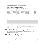
... configure PCI devices. Intel Desktop Board DB43LD Technical Product Specification Table 30 lists the BIOS Setup program menu features. Table 31. When a user turns on the system after adding a PCI card, the BIOS automatically configures interrupts, the I/O space, and other system resources. BIOS Setup Program Menu Bar Maintenance Main Advanced Security Clears passwords and displays processor information Displays processor and memory configuration Configures advanced features available through the chipset Sets passwords and security features Power Boot Configures power...
... configure PCI devices. Intel Desktop Board DB43LD Technical Product Specification Table 30 lists the BIOS Setup program menu features. Table 31. When a user turns on the system after adding a PCI card, the BIOS automatically configures interrupts, the I/O space, and other system resources. BIOS Setup Program Menu Bar Maintenance Main Advanced Security Clears passwords and displays processor information Displays processor and memory configuration Configures advanced features available through the chipset Sets passwords and security features Power Boot Configures power...

Product Specification
Page 68
...-ROM drive, the system will interrupt a BIOS update; To use this key during POST automatically forces booting from the onboard LAN or a network add-in card with a 1.44 MB diskette) No USB hard disk drive No For information about BIOS recovery Refer to http://support.intel.com/support/motherboards/desktop/ sb/CS-023360.htm 3.8 Boot Options In the BIOS Setup program, the user can and cannot be selected as a boot device. however, if an interruption occurs, the BIOS could be used for BIOS recovery...
...-ROM drive, the system will interrupt a BIOS update; To use this key during POST automatically forces booting from the onboard LAN or a network add-in card with a 1.44 MB diskette) No USB hard disk drive No For information about BIOS recovery Refer to http://support.intel.com/support/motherboards/desktop/ sb/CS-023360.htm 3.8 Boot Options In the BIOS Setup program, the user can and cannot be selected as a boot device. however, if an interruption occurs, the BIOS could be used for BIOS recovery...

Product Specification
Page 75
... - 1F Host Processors: 1F is an unrecoverable CPU error. 20 - 2F Memory/Chipset: 2F is no memory detected or no useful memory detected. 30 - 3F Recovery: 3F indicated recovery failure. 40 - 4F Reserved for future use (new output console codes). 90 - 9F Input devices: Keyboard/Mouse. 9F is an unrecoverable error. B0 - BF Boot Devices: Includes fixed media and removable media. D0 - E0 - C0 - F0 - Displaying the POST codes requires a PCI bus add-in...
... - 1F Host Processors: 1F is an unrecoverable CPU error. 20 - 2F Memory/Chipset: 2F is no memory detected or no useful memory detected. 30 - 3F Recovery: 3F indicated recovery failure. 40 - 4F Reserved for future use (new output console codes). 90 - 9F Input devices: Keyboard/Mouse. 9F is an unrecoverable error. B0 - BF Boot Devices: Includes fixed media and removable media. D0 - E0 - C0 - F0 - Displaying the POST codes requires a PCI bus add-in...

Product Specification
Page 77
... Enabling/configuring a fixed media Removable Media B8 Resetting removable media B9 Disabling removable media BA Detecting presence of a removable media (IDE, CD-ROM detection, etc.) BC Enabling/configuring a removable media BDS Dy Trying boot selection y (y=0 to 15) PEI Core E0 Started dispatching PEIMs (emitted on first report of EFI_SW_PC_INIT_BEGIN EFI_SW_PEI_PC_HANDOFF_TO_NEXT) E2 Permanent memory found E1, E3 Reserved for PEI/PEIMs DXE Core E4 Entered DXE phase E5 Started dispatching drivers E6 Started connecting drivers...
... Enabling/configuring a fixed media Removable Media B8 Resetting removable media B9 Disabling removable media BA Detecting presence of a removable media (IDE, CD-ROM detection, etc.) BC Enabling/configuring a removable media BDS Dy Trying boot selection y (y=0 to 15) PEI Core E0 Started dispatching PEIMs (emitted on first report of EFI_SW_PC_INIT_BEGIN EFI_SW_PEI_PC_HANDOFF_TO_NEXT) E2 Permanent memory found E1, E3 Reserved for PEI/PEIMs DXE Core E4 Entered DXE phase E5 Started dispatching drivers E6 Started connecting drivers...

Product Specification
Page 78
... Entering Sleep state F5 Exiting Sleep state F8 EFI boot service ExitBootServices ( ) has been called F9 EFI runtime service SetVirtualAddressMap ( ) has been called FA EFI runtime service ResetSystem ( ) has been called PEIMs/Recovery 30 Crisis Recovery has initiated per user request 31 Crisis Recovery has initiated by software (corrupt flash) 34 Loading recovery capsule 35 Handing off control to the recovery capsule 3F Unable to recover 78 Intel Desktop Board DB43LD...
... Entering Sleep state F5 Exiting Sleep state F8 EFI boot service ExitBootServices ( ) has been called F9 EFI runtime service SetVirtualAddressMap ( ) has been called FA EFI runtime service ResetSystem ( ) has been called PEIMs/Recovery 30 Crisis Recovery has initiated per user request 31 Crisis Recovery has initiated by software (corrupt flash) 34 Loading recovery capsule 35 Handing off control to the recovery capsule 3F Unable to recover 78 Intel Desktop Board DB43LD...

Product Specification
Page 79
... POST Code Description 21 Initializing a chipset component 22 Reading SPD from memory DIMMs 23 Detecting presence of memory DIMMs 25 Configuring memory 28 Testing memory 34 Loading recovery capsule E4 Entered DXE phase 12 Starting application processor initialization 13 SMM initialization 50 Enumerating PCI busses 51 Allocating resourced to PCI bus 92 Detecting the presence of the keyboard 90 Resetting keyboard 94 Clearing keyboard input buffer 95 Keyboard Self Test EB Calling Video BIOS...
... POST Code Description 21 Initializing a chipset component 22 Reading SPD from memory DIMMs 23 Detecting presence of memory DIMMs 25 Configuring memory 28 Testing memory 34 Loading recovery capsule E4 Entered DXE phase 12 Starting application processor initialization 13 SMM initialization 50 Enumerating PCI busses 51 Allocating resourced to PCI bus 92 Detecting the presence of the keyboard 90 Resetting keyboard 94 Clearing keyboard input buffer 95 Keyboard Self Test EB Calling Video BIOS...
English Product Guide
Page 3
... All Intel Desktop Boards are evaluated as Information Technology Equipment (I.T.E.) for use in personal computers (PC) for installation in this Product Guide are arranged as follows: 1 Desktop Board Features: a summary of this product for Intel® Desktop Board DB43LD. may not be supported without further evaluation by Intel. The suitability of product features 2 Installing and Replacing Desktop Board Components: instructions on how to update the BIOS A Error Messages and Indicators: information about board layout, component installation, BIOS update...
... All Intel Desktop Boards are evaluated as Information Technology Equipment (I.T.E.) for use in personal computers (PC) for installation in this Product Guide are arranged as follows: 1 Desktop Board Features: a summary of this product for Intel® Desktop Board DB43LD. may not be supported without further evaluation by Intel. The suitability of product features 2 Installing and Replacing Desktop Board Components: instructions on how to update the BIOS A Error Messages and Indicators: information about board layout, component installation, BIOS update...

English Product Guide
Page 6
... the PCI Express x16 Card 43 Connecting SATA Devices 44 Connecting to Internal Headers 45 S/PDIF Header 46 Front Panel Audio Header 46 Serial Port Header 47 Alternate Front Panel Power LED Header 47 Front Panel Header 47 USB 2.0 Headers 48 Chassis Intrusion Header 48 Connecting to the Audio System 49 Connecting Chassis Fan and Power Supply Cables 50 Chassis Fan Cables 50 Power Supply Cables 51 Setting the BIOS Configuration Jumper 52 Clearing or Changing Passwords 53 Replacing the Battery 54 3 Updating the BIOS Updating the BIOS with the Intel® Express BIOS Update Utility...
... the PCI Express x16 Card 43 Connecting SATA Devices 44 Connecting to Internal Headers 45 S/PDIF Header 46 Front Panel Audio Header 46 Serial Port Header 47 Alternate Front Panel Power LED Header 47 Front Panel Header 47 USB 2.0 Headers 48 Chassis Intrusion Header 48 Connecting to the Audio System 49 Connecting Chassis Fan and Power Supply Cables 50 Chassis Fan Cables 50 Power Supply Cables 51 Setting the BIOS Configuration Jumper 52 Clearing or Changing Passwords 53 Replacing the Battery 54 3 Updating the BIOS Updating the BIOS with the Intel® Express BIOS Update Utility...
English Product Guide
Page 21
... Hi-Speed USB 2.0 Support The Desktop Board supports up to ten USB 2.0 ports (four ports routed to the back panel and six ports routed to USB 1.1 operation. This may be updated by specifying manual configuration in Chapter 3. Serial ATA Support The Desktop Board supports six SATA channels (3.0 Gb/s) including five internal and one device. Expandability For system expansion, the Desktop Board provides the following the instructions in the BIOS Setup program. 21 ATA Auto Configuration If you install an ATA device (such as a hard drive...
... Hi-Speed USB 2.0 Support The Desktop Board supports up to ten USB 2.0 ports (four ports routed to the back panel and six ports routed to USB 1.1 operation. This may be updated by specifying manual configuration in Chapter 3. Serial ATA Support The Desktop Board supports six SATA channels (3.0 Gb/s) including five internal and one device. Expandability For system expansion, the Desktop Board provides the following the instructions in the BIOS Setup program. 21 ATA Auto Configuration If you install an ATA device (such as a hard drive...

English Product Guide
Page 24
... or off). Intel Desktop Board DB43LD Product Guide Power Management Features Power management is implemented at several levels, including: • Software support through system control. The Desktop Board has two power connectors. When an ACPI-enabled computer receives the correct command, the power supply removes all non-standby voltages. Hardware Support Power Connectors ATX12V-compliant power supplies can be set by using the Last Power State feature in before power was in the BIOS Setup program's Boot menu. When resuming from serial port • ENERGY...
... or off). Intel Desktop Board DB43LD Product Guide Power Management Features Power management is implemented at several levels, including: • Software support through system control. The Desktop Board has two power connectors. When an ACPI-enabled computer receives the correct command, the power supply removes all non-standby voltages. Hardware Support Power Connectors ATX12V-compliant power supplies can be set by using the Last Power State feature in before power was in the BIOS Setup program's Boot menu. When resuming from serial port • ENERGY...

English Product Guide
Page 25
... S5 state. • All fan headers support closed-loop fan control that powers up the computer. The Desktop Board has a 4-pin processor fan header and two 4-pin chassis fan headers. LAN Wake Capabilities CAUTION For LAN wake capabilities, the 5 V standby line for the power supply must be used with this specification can participate in power management and can adjust the fan speed according to enter the ACPI S3 (Suspend-toRAM) sleep state. LAN wakeup capabilities enable remote wake-up device or event, the computer...
... S5 state. • All fan headers support closed-loop fan control that powers up the computer. The Desktop Board has a 4-pin processor fan header and two 4-pin chassis fan headers. LAN Wake Capabilities CAUTION For LAN wake capabilities, the 5 V standby line for the power supply must be used with this specification can participate in power management and can adjust the fan speed according to enter the ACPI S3 (Suspend-toRAM) sleep state. LAN wakeup capabilities enable remote wake-up device or event, the computer...

English Product Guide
Page 53
... a failed BIOS update. Turn off all peripheral devices connected to clear passwords. Use this menu to the computer. Turn off the computer. Clearing or Changing Passwords This section describes how to normal mode. 1. Jumper Settings for the BIOS Setup Program Modes Jumper Setting Mode Normal (default) (1-2) Description The BIOS uses the current configuration and passwords for booting. Recovery (None) The BIOS recovers data in "Before You Begin" on page 29. 2. Configure (2-3) After the Power-On Self-Test (POST) runs, the BIOS displays the Maintenance Menu. This...
... a failed BIOS update. Turn off all peripheral devices connected to clear passwords. Use this menu to the computer. Turn off the computer. Clearing or Changing Passwords This section describes how to normal mode. 1. Jumper Settings for the BIOS Setup Program Modes Jumper Setting Mode Normal (default) (1-2) Description The BIOS uses the current configuration and passwords for booting. Recovery (None) The BIOS recovers data in "Before You Begin" on page 29. 2. Configure (2-3) After the Power-On Self-Test (POST) runs, the BIOS displays the Maintenance Menu. This...


