

D945PLNM Technical Product Specification
Page 5
... Summary 10 1.1.2 Board Layout 12 1.1.3 Block Diagram 14 1.2 Online Support ...15 1.3 Processor ...15 1.4 System Memory ...16 1.4.1 Memory Configurations 17 1.5 Intel® 945PL Chipset...20 1.5.1 USB ...20 1.5.2 IDE Support 21 1.5.3 Real-Time Clock, CMOS SRAM, and Battery 22 1.6 PCI Express* Connectors 27 1.7 Legacy I/O Controller 27 1.7.1 Serial Port...27 1.7.2 Parallel Port 28 1.7.3 Diskette Drive Controller 28 1.7.4 Keyboard and Mouse Interface 28 1.8 Audio Subsystem ...29 1.8.1 Audio Subsystem Software 29 1.8.2 Audio Connectors 29 1.8.3 6-Channel (5.1) Audio Subsystem 30...
... Summary 10 1.1.2 Board Layout 12 1.1.3 Block Diagram 14 1.2 Online Support ...15 1.3 Processor ...15 1.4 System Memory ...16 1.4.1 Memory Configurations 17 1.5 Intel® 945PL Chipset...20 1.5.1 USB ...20 1.5.2 IDE Support 21 1.5.3 Real-Time Clock, CMOS SRAM, and Battery 22 1.6 PCI Express* Connectors 27 1.7 Legacy I/O Controller 27 1.7.1 Serial Port...27 1.7.2 Parallel Port 28 1.7.3 Diskette Drive Controller 28 1.7.4 Keyboard and Mouse Interface 28 1.8 Audio Subsystem ...29 1.8.1 Audio Subsystem Software 29 1.8.2 Audio Connectors 29 1.8.3 6-Channel (5.1) Audio Subsystem 30...
D945PLNM Technical Product Specification
Page 6
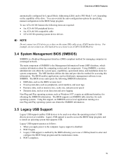
... PCI IDE Support 74 3.4 System Management BIOS (SMBIOS 75 3.5 Legacy USB Support...75 3.6 BIOS Updates ...76 3.6.1 Language Support 76 3.6.2 Custom Splash Screen 76 3.7 Boot Options ...77 3.7.1 CD-ROM Boot 77 3.7.2 Network Boot 77 3.7.3 Booting Without Attached Devices 77 3.7.4 Changing the Default Boot Device During POST 77 3.8 Adjusting Boot Speed 78 3.8.1 Peripheral Selection and Configuration 78 3.8.2 BIOS Boot Optimizations 78 3.9 BIOS Security Features 79 4 Error Messages and Beep Codes 4.1 Speaker ...81 4.2 BIOS Beep Codes...81 4.3 BIOS Error Messages 81 4.4 Port 80h POST...
... PCI IDE Support 74 3.4 System Management BIOS (SMBIOS 75 3.5 Legacy USB Support...75 3.6 BIOS Updates ...76 3.6.1 Language Support 76 3.6.2 Custom Splash Screen 76 3.7 Boot Options ...77 3.7.1 CD-ROM Boot 77 3.7.2 Network Boot 77 3.7.3 Booting Without Attached Devices 77 3.7.4 Changing the Default Boot Device During POST 77 3.8 Adjusting Boot Speed 78 3.8.1 Peripheral Selection and Configuration 78 3.8.2 BIOS Boot Optimizations 78 3.9 BIOS Security Features 79 4 Error Messages and Beep Codes 4.1 Speaker ...81 4.2 BIOS Beep Codes...81 4.3 BIOS Error Messages 81 4.4 Port 80h POST...

D945PLNM Technical Product Specification
Page 7
... 12 47 15. LAN Connector LED States 32 5. Effects of the Jumper Block 56 17. DMA Channels ...43 11. Front Panel Audio Connector 50 17. Auxiliary Front Panel Power/Sleep LED Connector 52 24. Front/Back Panel Audio Connector Options for Front Panel USB Connectors 55 16. Board Dimensions...57 18. Front and Rear Chassis Fan Connectors 50 21. Connection Diagram for 6-Channel (5.1) Audio Subsystem .... 30 8. 6-Channel (5.1) Audio Subsystem Block Diagram 30 9. Supported Memory Configurations 16 4. PCI Configuration Space Map 43 12. Processor Fan Connector 50 20...
... 12 47 15. LAN Connector LED States 32 5. Effects of the Jumper Block 56 17. DMA Channels ...43 11. Front Panel Audio Connector 50 17. Auxiliary Front Panel Power/Sleep LED Connector 52 24. Front/Back Panel Audio Connector Options for Front Panel USB Connectors 55 16. Board Dimensions...57 18. Front and Rear Chassis Fan Connectors 50 21. Connection Diagram for 6-Channel (5.1) Audio Subsystem .... 30 8. 6-Channel (5.1) Audio Subsystem Block Diagram 30 9. Supported Memory Configurations 16 4. PCI Configuration Space Map 43 12. Processor Fan Connector 50 20...
D945PLNM Technical Product Specification
Page 8
... POST Code Ranges 82 43. BIOS Setup Configuration Jumper Settings 56 28. Thermal Considerations for a Two-Color Power LED 54 27. Safety Regulations ...65 33. BIOS Setup Program Menu Bar 74 37. Boot Device Menu Options 77 39. Beep Codes ...81 41. DC Loading Characteristics 59 29. Environmental Specifications 64 32. EMC Regulations ...70 35. States for Components 63 31. Lead Free Desktop Board 69 34. BIOS Setup Program Function Keys 74 38. Intel Desktop Board D945PLNM Technical Product Specification 26. Fan Connector...
... POST Code Ranges 82 43. BIOS Setup Configuration Jumper Settings 56 28. Thermal Considerations for a Two-Color Power LED 54 27. Safety Regulations ...65 33. BIOS Setup Program Menu Bar 74 37. Boot Device Menu Options 77 39. Beep Codes ...81 41. DC Loading Characteristics 59 29. Environmental Specifications 64 32. EMC Regulations ...70 35. States for Components 63 31. Lead Free Desktop Board 69 34. BIOS Setup Program Function Keys 74 38. Intel Desktop Board D945PLNM Technical Product Specification 26. Fan Connector...
D945PLNM Technical Product Specification
Page 10
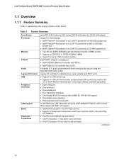
...6-channel (5.1) audio subsystem with three analog audio outputs using the Sigmatel* 9220 audio codec Legacy I/O Control Legacy I/O controller for diskette drive, serial, parallel, and PS/2* ports USB • Support for USB 2.0 devices • Support for USB anti-theft circuitry on back-panel USB connectors (requires the use of the board. Table 1. Intel Desktop Board D945PLNM Technical Product Specification 1.1 Overview 1.1.1 Feature Summary Table 1 summarizes the major features of Intel® Platform Administrator Technology software, available separately) Peripheral Interfaces LAN...
...6-channel (5.1) audio subsystem with three analog audio outputs using the Sigmatel* 9220 audio codec Legacy I/O Control Legacy I/O controller for diskette drive, serial, parallel, and PS/2* ports USB • Support for USB 2.0 devices • Support for USB anti-theft circuitry on back-panel USB connectors (requires the use of the board. Table 1. Intel Desktop Board D945PLNM Technical Product Specification 1.1 Overview 1.1.1 Feature Summary Table 1 summarizes the major features of Intel® Platform Administrator Technology software, available separately) Peripheral Interfaces LAN...

D945PLNM Technical Product Specification
Page 43
...port (Note 1) Intel High Definition Audio Controller PCI Express port 1 PCI Express port 2 PCI Express port 3 PCI Express port 4 USB UHCI controller 1 USB UHCI controller 2 USB UHCI controller 3 USB UHCI controller 4 EHCI controller PCI bridge PCI controller Parallel ATA IDE controller Serial ATA controller SMBus controller PCI Conventional bus connector 1 PCI Conventional bus connector 2 Intel® 82562 10/100 Mbits/sec LAN PLC PCI Express video controller (if present) (Note 1) Notes: 1. Present only when a PCI Express x16 graphics card is dynamic and can change based on add-in cards used...
...port (Note 1) Intel High Definition Audio Controller PCI Express port 1 PCI Express port 2 PCI Express port 3 PCI Express port 4 USB UHCI controller 1 USB UHCI controller 2 USB UHCI controller 3 USB UHCI controller 4 EHCI controller PCI bridge PCI controller Parallel ATA IDE controller Serial ATA controller SMBus controller PCI Conventional bus connector 1 PCI Conventional bus connector 2 Intel® 82562 10/100 Mbits/sec LAN PLC PCI Express video controller (if present) (Note 1) Notes: 1. Present only when a PCI Express x16 graphics card is dynamic and can change based on add-in cards used...

D945PLNM Technical Product Specification
Page 47
... 2.7.1 Back Panel Connectors Figure 12 shows the location of the back panel connectors. The back panel connectors are connected to power headphones or amplified speakers only. Poor audio quality occurs if passive (non-amplified) speakers are color-coded. Back Panel Connectors Shown in Figure 12 Item/callout from Figure 12 Description A PS/2 mouse port [Green] B PS/2 keyboard port [Purple] C Serial port A [Teal] D Parallel port [Burgundy] E USB ports (two) [Yellow] F LAN G USB ports (two) [Yellow] H Audio line in...
... 2.7.1 Back Panel Connectors Figure 12 shows the location of the back panel connectors. The back panel connectors are connected to power headphones or amplified speakers only. Poor audio quality occurs if passive (non-amplified) speakers are color-coded. Back Panel Connectors Shown in Figure 12 Item/callout from Figure 12 Description A PS/2 mouse port [Green] B PS/2 keyboard port [Purple] C Serial port A [Teal] D Parallel port [Burgundy] E USB ports (two) [Yellow] F LAN G USB ports (two) [Yellow] H Audio line in...

D945PLNM Technical Product Specification
Page 73
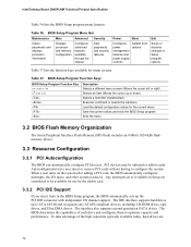
..., POST, the PCI auto-configuration utility, and Plug and Play support. The BIOS displays a message during POST identifying the type of BIOS Features What This Chapter Contains 3.1 Introduction ...73 3.2 BIOS Flash Memory Organization 74 3.3 Resource Configuration 74 3.4 System Management BIOS (SMBIOS 75 3.5 Legacy USB Support...75 3.6 BIOS Updates ...76 3.7 Boot Options ...77 3.8 Adjusting Boot Speed 78 3.9 BIOS Security Features 79 3.1 Introduction The boards use an Intel BIOS that is stored in configure mode. 73 The menu bar is accessed by pressing the key after the Power...
..., POST, the PCI auto-configuration utility, and Plug and Play support. The BIOS displays a message during POST identifying the type of BIOS Features What This Chapter Contains 3.1 Introduction ...73 3.2 BIOS Flash Memory Organization 74 3.3 Resource Configuration 74 3.4 System Management BIOS (SMBIOS 75 3.5 Legacy USB Support...75 3.6 BIOS Updates ...76 3.7 Boot Options ...77 3.8 Adjusting Boot Speed 78 3.9 BIOS Security Features 79 3.1 Introduction The boards use an Intel BIOS that is stored in configure mode. 73 The menu bar is accessed by pressing the key after the Power...
D945PLNM Technical Product Specification
Page 74
.../O channel support. Any interrupts set to Setup program options Table 37 lists the function keys available for use by the add-in card. 3.3.2 PCI IDE Support If you select Auto in cards. The interface also supports second-generation SATA drives. BIOS Setup Program Menu Bar Maintenance Main Advanced Security Clears passwords and displays processor information Displays processor and memory configuration Configures advanced features available through the chipset Sets passwords and security features Power Boot Configures power management features and power supply controls Selects boot...
.../O channel support. Any interrupts set to Setup program options Table 37 lists the function keys available for use by the add-in card. 3.3.2 PCI IDE Support If you select Auto in cards. The interface also supports second-generation SATA drives. BIOS Setup Program Menu Bar Maintenance Main Advanced Security Clears passwords and displays processor information Displays processor and memory configuration Configures advanced features available through the chipset Sets passwords and security features Power Boot Configures power management features and power supply controls Selects boot...
D945PLNM Technical Product Specification
Page 75
..., serial numbers, and asset tags • Resource data, such as memory size, cache size, and processor speed • Dynamic data, such as event detection and error logging Non-Plug and Play operating systems, such as third-party management software to use a USB keyboard to enter and configure the BIOS Setup program and the maintenance menu. 4. For example, do not connect an ATA hard drive as a slave to an ATAPI CD-ROM drive...
..., serial numbers, and asset tags • Resource data, such as memory size, cache size, and processor speed • Dynamic data, such as event detection and error logging Non-Plug and Play operating systems, such as third-party management software to use a USB keyboard to enter and configure the BIOS Setup program and the maintenance menu. 4. For example, do not connect an ATA hard drive as a slave to an ATAPI CD-ROM drive...

D945PLNM Technical Product Specification
Page 77
... displayed. This selection allows booting from the onboard LAN or a network add-in the CD-ROM drive, the system will attempt to boot from the LAN. Boot devices are not present: • Video adapter • Keyboard • Mouse 3.7.4 Changing the Default Boot Device During POST Pressing the key during POST automatically forces booting from the next defined drive. 3.7.2 Network Boot The network can choose to be the first boot device, the hard drive second, and the ATAPI CD-ROM third. Boot Device Menu Options Boot Device Menu...
... displayed. This selection allows booting from the onboard LAN or a network add-in the CD-ROM drive, the system will attempt to boot from the LAN. Boot devices are not present: • Video adapter • Keyboard • Mouse 3.7.4 Changing the Default Boot Device During POST Pressing the key during POST automatically forces booting from the next defined drive. 3.7.2 Network Boot The network can choose to be the first boot device, the hard drive second, and the ATAPI CD-ROM third. Boot Device Menu Options Boot Device Menu...

D945PLNM Technical Product Specification
Page 78
...-in adapter features, such as logo displays, screen repaints, or mode changes in the Drive Configuration Submenu of option ROM boot time. Intel Desktop Board D945PLNM Technical Product Specification 3.8 Adjusting Boot Speed These factors affect system boot speed: • Selecting and configuring peripherals properly • Optimized BIOS boot parameters 3.8.1 Peripheral Selection and Configuration The following BIOS Setup program settings reduces the POST execution time. • In the Boot Menu, set the hard disk drive as the first boot device. This can reduce up to...
...-in adapter features, such as logo displays, screen repaints, or mode changes in the Drive Configuration Submenu of option ROM boot time. Intel Desktop Board D945PLNM Technical Product Specification 3.8 Adjusting Boot Speed These factors affect system boot speed: • Selecting and configuring peripherals properly • Optimized BIOS boot parameters 3.8.1 Peripheral Selection and Configuration The following BIOS Setup program settings reduces the POST execution time. • In the Boot Menu, set the hard disk drive as the first boot device. This can reduce up to...

D945PLNM Technical Product Specification
Page 82
... an unrecoverable error. EF boot/S3: resume failure. 82 AF B0 - Recovery: 3F indicated recovery failure. EE: Miscellaneous codes. Reserved for new busses). Reserved for future use (for future use (new input console codes). Input devices: Keyboard/Mouse. 9F is an unrecoverable error. Boot Devices: Includes fixed media and removable media. Reserved for future use . Intel Desktop Board D945PLNM Technical Product Specification 4.4 Port 80h POST Codes During the POST, the BIOS generates diagnostic progress codes (POST-codes) to I /O Busses: PCI, USB, ISA...
... an unrecoverable error. EF boot/S3: resume failure. 82 AF B0 - Recovery: 3F indicated recovery failure. EE: Miscellaneous codes. Reserved for new busses). Reserved for future use (for future use (new input console codes). Input devices: Keyboard/Mouse. 9F is an unrecoverable error. Boot Devices: Includes fixed media and removable media. Reserved for future use . Intel Desktop Board D945PLNM Technical Product Specification 4.4 Port 80h POST Codes During the POST, the BIOS generates diagnostic progress codes (POST-codes) to I /O Busses: PCI, USB, ISA...

D945PLNM Technical Product Specification
Page 83
... the memory controller and the DIMMs Configuring memory Optimizing memory settings Initializing memory, such as ECC init Testing memory PCI Bus Enumerating PCI busses Allocating resources to PCI bus Hot Plug PCI controller initialization Reserved for PCI Bus USB Resetting USB bus Reserved for USB ATA/ATAPI/SATA Resetting PATA/SATA bus and all devices Reserved for ATA SMBus Resetting SMBUS Reserved for SMBUS Local Console Resetting the VGA controller Disabling the VGA controller Enabling the VGA controller Remote Console Resetting the console controller Disabling the console controller Enabling...
... the memory controller and the DIMMs Configuring memory Optimizing memory settings Initializing memory, such as ECC init Testing memory PCI Bus Enumerating PCI busses Allocating resources to PCI bus Hot Plug PCI controller initialization Reserved for PCI Bus USB Resetting USB bus Reserved for USB ATA/ATAPI/SATA Resetting PATA/SATA bus and all devices Reserved for ATA SMBus Resetting SMBUS Reserved for SMBUS Local Console Resetting the VGA controller Disabling the VGA controller Enabling the VGA controller Remote Console Resetting the console controller Disabling the console controller Enabling...
D945PLNM Desktop Board Specification Update
Page 12
Intel® Desktop Board D945PLNM Specification Update ERRATA 1. IMPLICATION: Some PCI Express x1 add-in cards may not fully connect to the PCI Express x1 connector slot, due to interference between capacitors in the keep-out zone and I/O connectors on the add-in card that are located on the I/O bracket, in the keep-out zone behind the PCI Express* x1 connector slot. The Placement of Capacitors Behind the PCI Express* x1 Connector Slot May Prohibit Some...
Intel® Desktop Board D945PLNM Specification Update ERRATA 1. IMPLICATION: Some PCI Express x1 add-in cards may not fully connect to the PCI Express x1 connector slot, due to interference between capacitors in the keep-out zone and I/O connectors on the add-in card that are located on the I/O bracket, in the keep-out zone behind the PCI Express* x1 connector slot. The Placement of Capacitors Behind the PCI Express* x1 Connector Slot May Prohibit Some...
English Product Guide
Page 3
... about board layout, component installation, BIOS update, and regulatory requirements for Intel® Desktop Board D945PLNM. iii NOTE Notes call attention to important information. may not be supported without further evaluation by Intel. Preface This Product Guide gives information about BIOS error messages and beep codes B Regulatory Compliance: safety and EMC regulations, product certification Conventions The following conventions are evaluated as Information Technology Equipment (I.T.E.) for use in personal...
... about board layout, component installation, BIOS update, and regulatory requirements for Intel® Desktop Board D945PLNM. iii NOTE Notes call attention to important information. may not be supported without further evaluation by Intel. Preface This Product Guide gives information about BIOS error messages and beep codes B Regulatory Compliance: safety and EMC regulations, product certification Conventions The following conventions are evaluated as Information Technology Equipment (I.T.E.) for use in personal...
English Product Guide
Page 6
...Express x16 Card 35 Removing the PCI Express x16 Card 36 Connecting the IDE Cable...37 Connecting the Serial ATA (SATA) Cable 38 Connecting Internal Headers 39 Installing a Front Panel Audio Solution for Intel® High Definition Audio 40 Connecting to the USB 2.0 Header 41 Connecting to the Front Panel Header 41 Connecting to the Flexible Audio System 42 Connecting Chassis Fan and Power Cables 43 Connecting Chassis Fan Cables 43 Connecting Power Cables 44 Other Connectors...45 Setting the BIOS Configuration Jumper 46 Clearing Passwords ...47 Back Panel Connectors...48 3 Updating...
...Express x16 Card 35 Removing the PCI Express x16 Card 36 Connecting the IDE Cable...37 Connecting the Serial ATA (SATA) Cable 38 Connecting Internal Headers 39 Installing a Front Panel Audio Solution for Intel® High Definition Audio 40 Connecting to the USB 2.0 Header 41 Connecting to the Front Panel Header 41 Connecting to the Flexible Audio System 42 Connecting Chassis Fan and Power Cables 43 Connecting Chassis Fan Cables 43 Connecting Power Cables 44 Other Connectors...45 Setting the BIOS Configuration Jumper 46 Clearing Passwords ...47 Back Panel Connectors...48 3 Updating...
English Product Guide
Page 18
... access to the chassis intrusion header on the desktop board. Related Links: For instructions on resetting the password, see Clearing Passwords on page 47. If only the supervisor password is booted. The security feature uses a mechanical switch on the chassis that restrict whether the BIOS Setup program can be accessed and who can be connected to view and change all Setup options. PCI and PCI Express* Auto Configuration If you install a PCI/PCI Express add-in card in your computer, the PCI/PCI Express autoconfiguration utility...
... access to the chassis intrusion header on the desktop board. Related Links: For instructions on resetting the password, see Clearing Passwords on page 47. If only the supervisor password is booted. The security feature uses a mechanical switch on the chassis that restrict whether the BIOS Setup program can be accessed and who can be connected to view and change all Setup options. PCI and PCI Express* Auto Configuration If you install a PCI/PCI Express add-in card in your computer, the PCI/PCI Express autoconfiguration utility...

English Product Guide
Page 47
... and press . Setup displays the maintenance menu again. 9. Disconnect the computer's power cord from the AC power source (wall outlet or power adapter). 3. Installing and Replacing Desktop Board Components Clearing Passwords This procedure assumes that you confirm clearing the password. Disconnect the computer's power cord from the AC power source. 11. The computer starts the Setup program. Turn off the computer. Turn off all peripheral devices connected to normal mode. 1. Remove the computer cover...
... and press . Setup displays the maintenance menu again. 9. Disconnect the computer's power cord from the AC power source (wall outlet or power adapter). 3. Installing and Replacing Desktop Board Components Clearing Passwords This procedure assumes that you confirm clearing the password. Disconnect the computer's power cord from the AC power source. 11. The computer starts the Setup program. Turn off the computer. Turn off all peripheral devices connected to normal mode. 1. Remove the computer cover...

Simplified Chinese Product Guide
Page 10
... Framework • 4 Mbit SMBIOS • Intel® Rapid BIOS Boot BIOS Intel® Express BIOS Update BIOS 更新) 电源管理 ACPI RAM (STR) • USB、PCI Express、PS/2、LAN 硬件管理 Intel® Precision Cooling Technology D945PLNM TPS)、BIOS http://support.intel.com/support/motherboards/desktop/ Microsoft Windows* XP Media Center Edition 2005 • Microsoft Windows XP Professional • Microsoft Windows XP Professional x64 Edition • Microsoft...
... Framework • 4 Mbit SMBIOS • Intel® Rapid BIOS Boot BIOS Intel® Express BIOS Update BIOS 更新) 电源管理 ACPI RAM (STR) • USB、PCI Express、PS/2、LAN 硬件管理 Intel® Precision Cooling Technology D945PLNM TPS)、BIOS http://support.intel.com/support/motherboards/desktop/ Microsoft Windows* XP Media Center Edition 2005 • Microsoft Windows XP Professional • Microsoft Windows XP Professional x64 Edition • Microsoft...


