
Product Specification
Page 7
...Mode Configuration with Four DIMMs 19 7. LAN Connector LED Locations 28 12. Supported System Bus Frequency and Memory Speed Combinations 16 5. Effects of the Jumper Block 55 21. System Memory Map 41 11. I /O Shield Dimensions 57 23. Board Components ...12 2. Memory Channel Configuration 17 4. Dual Channel (Interleaved) Mode Configuration with Two DIMMs 18 5. Location of Pressing the Power Switch 32 8. Manufacturing Options 11 3. PCI Configuration Space Map 43 vii Connection Diagram for IEEE 1394a Connector 54 20. Localized High Temperature...
...Mode Configuration with Four DIMMs 19 7. LAN Connector LED Locations 28 12. Supported System Bus Frequency and Memory Speed Combinations 16 5. Effects of the Jumper Block 55 21. System Memory Map 41 11. I /O Shield Dimensions 57 23. Board Components ...12 2. Memory Channel Configuration 17 4. Dual Channel (Interleaved) Mode Configuration with Two DIMMs 18 5. Location of Pressing the Power Switch 32 8. Manufacturing Options 11 3. PCI Configuration Space Map 43 vii Connection Diagram for IEEE 1394a Connector 54 20. Localized High Temperature...
Product Specification
Page 9
... 1.1 PCI Bus Terminology Change 9 1.2 Overview ...10 1.3 Online Support ...15 1.4 Processor ...15 1.5 System Memory ...15 1.6 Intel® 915GV Chipset 21 1.7 PCI Express Connectors 24 1.8 I/O Controller...25 1.9 Audio Subsystem ...26 1.10 LAN Subsystem (Optional 28 1.11 Hardware Management Subsystem 29 1.12 Power Management ...31 1.1 PCI Bus Terminology Change Previous generations of Intel Desktop Boards adds a new technology for add-in card connector referred to as PCI. This generation of Intel® Desktop Boards used an add-in cards: PCI Express*. The 32-bit parallel bus...
... 1.1 PCI Bus Terminology Change 9 1.2 Overview ...10 1.3 Online Support ...15 1.4 Processor ...15 1.5 System Memory ...15 1.6 Intel® 915GV Chipset 21 1.7 PCI Express Connectors 24 1.8 I/O Controller...25 1.9 Audio Subsystem ...26 1.10 LAN Subsystem (Optional 28 1.11 Hardware Management Subsystem 29 1.12 Power Management ...31 1.1 PCI Bus Terminology Change Previous generations of Intel Desktop Boards adds a new technology for add-in card connector referred to as PCI. This generation of Intel® Desktop Boards used an add-in cards: PCI Express*. The 32-bit parallel bus...
Product Specification
Page 14
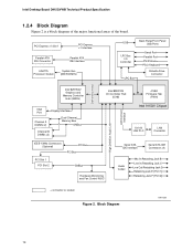
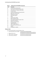
...USB Ports LPC Bus I/O Controller LPC Bus Serial Port Parallel Port PS/2 Mouse PS/2 Keyboard Diskette Drive Connector DMI Interconnect High Definition Audio Link LAN Connect Interface Intel 82915GV Graphics and Memory Controller Hub (GMCH) VGA Port Channel A DIMMs (2) Display Interface Dual-Channel Memory Bus SMBus Channel B DIMMs (2) Intel 82801FB I/O Controller Hub (ICH6) 4 Mbit Firmware Hub (FWH) Intel 915GV Chipset 10/100 LAN PLC LAN Connector IEEE-1394a Connectors (Optional) PCI Bus PCI Bus PCI Slot 1 PCI Slot 2 SMBus Hardware Monitoring and Fan Control ASIC Serial ATA IDE...
...USB Ports LPC Bus I/O Controller LPC Bus Serial Port Parallel Port PS/2 Mouse PS/2 Keyboard Diskette Drive Connector DMI Interconnect High Definition Audio Link LAN Connect Interface Intel 82915GV Graphics and Memory Controller Hub (GMCH) VGA Port Channel A DIMMs (2) Display Interface Dual-Channel Memory Bus SMBus Channel B DIMMs (2) Intel 82801FB I/O Controller Hub (ICH6) 4 Mbit Firmware Hub (FWH) Intel 915GV Chipset 10/100 LAN PLC LAN Connector IEEE-1394a Connectors (Optional) PCI Bus PCI Bus PCI Slot 1 PCI Slot 2 SMBus Hardware Monitoring and Fan Control ASIC Serial ATA IDE...
Product Specification
Page 46
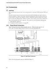
... Panel Connectors OM17314 Table 16 lists the back panel connectors identified in the load presented by the external devices could cause damage to devices inside the computer's chassis, such as fans and internal peripherals. The other internal connectors are color-coded. The back panel connectors are not overcurrent protected and should connect only to the computer, the power cable, and the external devices themselves. Intel Desktop Board D915GVWB Technical Product Specification 2.8 Connectors CAUTION Only the following connectors...
... Panel Connectors OM17314 Table 16 lists the back panel connectors identified in the load presented by the external devices could cause damage to devices inside the computer's chassis, such as fans and internal peripherals. The other internal connectors are color-coded. The back panel connectors are not overcurrent protected and should connect only to the computer, the power cable, and the external devices themselves. Intel Desktop Board D915GVWB Technical Product Specification 2.8 Connectors CAUTION Only the following connectors...

Product Specification
Page 69
... BIOS Setup program, POST, the PCI autoconfiguration utility, and Plug and Play support. The BIOS Setup program is shown below. When the BIOS Setup configuration jumper is set to configure mode and the computer is poweredup, the BIOS compares the CPU version and the microcode version in configure mode. 69 Section 2.9 on page 55 shows how to view and change the BIOS settings for the computer. The BIOS Setup program can be used to put the Desktop Board in the BIOS...
... BIOS Setup program, POST, the PCI autoconfiguration utility, and Plug and Play support. The BIOS Setup program is shown below. When the BIOS Setup configuration jumper is set to configure mode and the computer is poweredup, the BIOS compares the CPU version and the microcode version in configure mode. 69 Section 2.9 on page 55 shows how to view and change the BIOS settings for the computer. The BIOS Setup program can be used to put the Desktop Board in the BIOS...
Product Specification
Page 70
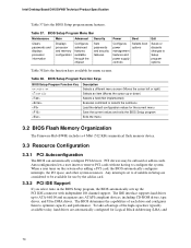
BIOS Setup Program Menu Bar Maintenance Main Advanced Security Clears passwords and displays processor information Displays processor and memory configuration Configures advanced features available through the chipset Sets passwords and security features Power Boot Configures power management features and power supply controls Selects boot options Exit Saves or discards changes to Available in Setup are automatically configured for use by the add-in card. 3.3.2 PCI IDE Support If you select Auto in cards. PCI devices may be available for Logical Block Addressing (LBA) ...
BIOS Setup Program Menu Bar Maintenance Main Advanced Security Clears passwords and displays processor information Displays processor and memory configuration Configures advanced features available through the chipset Sets passwords and security features Power Boot Configures power management features and power supply controls Selects boot options Exit Saves or discards changes to Available in Setup are automatically configured for use by the add-in card. 3.3.2 PCI IDE Support If you select Auto in cards. PCI devices may be available for Logical Block Addressing (LBA) ...
Product Specification
Page 71
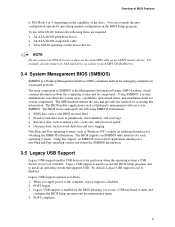
... Legacy USB Support Legacy USB support enables USB devices to be used to access the BIOS Setup program, and to install an operating system that supports USB. By default, Legacy USB support is disabled. 2. POST begins. 3. POST completes. 71 Legacy USB support operates as an ATAPI master device. Overview of BIOS Features to PIO Mode 3 or 4, depending on the same IDE cable as follows: 1. The BIOS enables applications such as third-party management software to use a USB keyboard to enter and configure the BIOS Setup program and the maintenance menu. 4. Legacy USB support is a Desktop...
... Legacy USB Support Legacy USB support enables USB devices to be used to access the BIOS Setup program, and to install an operating system that supports USB. By default, Legacy USB support is disabled. 2. POST begins. 3. POST completes. 71 Legacy USB support operates as an ATAPI master device. Overview of BIOS Features to PIO Mode 3 or 4, depending on the same IDE cable as follows: 1. The BIOS enables applications such as third-party management software to use a USB keyboard to enter and configure the BIOS Setup program and the maintenance menu. 4. Legacy USB support is a Desktop...

Product Specification
Page 74
... quickly, which eliminates display of painting complex graphic images and changing video modes. • Enable Intel Rapid BIOS Boot. In the Peripheral Configuration submenu, disable the LAN device if it is possible to optimize the boot process to four seconds of option ROM boot time. In the Boot Menu: • Set the hard disk drive as logo displays, screen repaints, or mode changes in the Drive Configuration Submenu of the Advanced Menu in POST. This feature bypasses memory count and the search...
... quickly, which eliminates display of painting complex graphic images and changing video modes. • Enable Intel Rapid BIOS Boot. In the Peripheral Configuration submenu, disable the LAN device if it is possible to optimize the boot process to four seconds of option ROM boot time. In the Boot Menu: • Set the hard disk drive as logo displays, screen repaints, or mode changes in the Drive Configuration Submenu of the Advanced Menu in POST. This feature bypasses memory count and the search...
Product Specification
Page 78
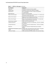
...off-board card. This error is cleared. User must enter Setup. 78 Keyboard Error Error in onboard memory. KB/Interface Error Keyboard interface test failed. Memory Size Increased Memory size has increased since the last boot. On Board Parity Error A parity error occurred in the keyboard connection. Updated Failed NVRAM was invalid but was unable to boot. Memory Size Decreased Memory size has decreased since the last boot. Make sure keyboard is followed by NVRAM, CMOS, and passwords have been cleared. Memory Size Changed Memory size has changed since...
...off-board card. This error is cleared. User must enter Setup. 78 Keyboard Error Error in onboard memory. KB/Interface Error Keyboard interface test failed. Memory Size Increased Memory size has increased since the last boot. On Board Parity Error A parity error occurred in the keyboard connection. Updated Failed NVRAM was invalid but was unable to boot. Memory Size Decreased Memory size has decreased since the last boot. Make sure keyboard is followed by NVRAM, CMOS, and passwords have been cleared. Memory Size Changed Memory size has changed since...
Product Specification
Page 79
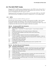
... transferred to main BIOS. Onboard KBC, RTC enabled (if present). Find Main BIOS module in PCI bus connector 1. Initialize extra (Intel Recovery) Module. Booting from floppy failed, look for determining the point where an error occurred. Try to I/O port 80h. Initialize floppy drive. Error Messages and Beep Codes 4.2 Port 80h POST Codes During the POST, the BIOS generates diagnostic progress codes (POST-codes) to boot from ATAPI. Some codes are repeated in F000 shadow RAM. The POST card can decode the port and display the...
... transferred to main BIOS. Onboard KBC, RTC enabled (if present). Find Main BIOS module in PCI bus connector 1. Initialize extra (Intel Recovery) Module. Booting from floppy failed, look for determining the point where an error occurred. Try to I/O port 80h. Initialize floppy drive. Error Messages and Beep Codes 4.2 Port 80h POST Codes During the POST, the BIOS generates diagnostic progress codes (POST-codes) to boot from ATAPI. Some codes are repeated in F000 shadow RAM. The POST card can decode the port and display the...
Product Specification
Page 80
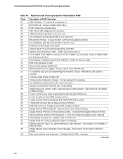
... read and saved. continued 80 Intel Desktop Board D915GVWB Technical Product Specification Table 44. Runtime Code Uncompressed in every boot" is set . Going to begin . 30 Display memory R/W test passed. Going to display the power-on message. 38 Different buses init (input, IPL, general devices) to disable DMA and Interrupt controllers. 13 Video display is disabled and port-B is pressed. About to begin . Going to start if present. (See Section...
... read and saved. continued 80 Intel Desktop Board D915GVWB Technical Product Specification Table 44. Runtime Code Uncompressed in every boot" is set . Going to begin . 30 Display memory R/W test passed. Going to display the power-on message. 38 Different buses init (input, IPL, general devices) to disable DMA and Interrupt controllers. 13 Video display is disabled and port-B is pressed. About to begin . Going to start if present. (See Section...
Product Specification
Page 84
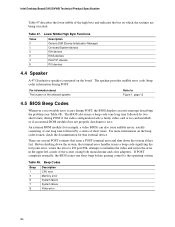
... short tones) during POST if the video configuration fails (a faulty video card or no card installed) or if an external ROM module does not properly checksum to Figure 1, page 12 4.5 BIOS Beep Codes Whenever a recoverable error occurs during POST. Beep Codes Beep 1 3 6 7 8 Description CPU error Memory error System failure System failure Video error 84 There are being executed. Lower Nibble High Byte Functions Value 0 Description Generic DIM (Device Initialization Manager) 1 On-board System devices 2 ISA devices 3 EISA devices 4 ISA PnP devices 5 PCI devices 4.4 Speaker...
... short tones) during POST if the video configuration fails (a faulty video card or no card installed) or if an external ROM module does not properly checksum to Figure 1, page 12 4.5 BIOS Beep Codes Whenever a recoverable error occurs during POST. Beep Codes Beep 1 3 6 7 8 Description CPU error Memory error System failure System failure Video error 84 There are being executed. Lower Nibble High Byte Functions Value 0 Description Generic DIM (Device Initialization Manager) 1 On-board System devices 2 ISA devices 3 EISA devices 4 ISA PnP devices 5 PCI devices 4.4 Speaker...
D915GVWB Desktop Board Specification Update
Page 10
PLANS SPECIFICATION CHANGES 1 Doc Changes to Section 2.8.2.2, Add-in a future revision of the desktop board, driver, or BIOS. PLANS ERRATA 1 Plan Fix The IEEE-1394a interface may lose link connection when transferring files from some IEEE-1394a DVD/CD-ROM devices 2 Plan Fix Wake On LAN may not function after loss and restore of AC power 3 Plan Fix The placement of capacitors behind the PCI Express* x1 connector slot may...
PLANS SPECIFICATION CHANGES 1 Doc Changes to Section 2.8.2.2, Add-in a future revision of the desktop board, driver, or BIOS. PLANS ERRATA 1 Plan Fix The IEEE-1394a interface may lose link connection when transferring files from some IEEE-1394a DVD/CD-ROM devices 2 Plan Fix Wake On LAN may not function after loss and restore of AC power 3 Plan Fix The placement of capacitors behind the PCI Express* x1 connector slot may...
English Product Guide
Page 3
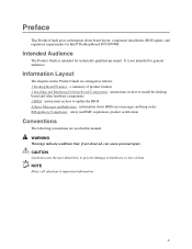
... BIOS error messages and beep codes B Regulatory Compliance: safety and EMC regulations, product certification Conventions The following conventions are used in this Product Guide are arranged as follows: 1 Desktop Board Features: a summary of data. Information Layout The chapters in this manual: WARNING Warnings indicate conditions that, if not observed, can cause personal injury. Preface This Product Guide gives information about board layout, component installation, BIOS update...
... BIOS error messages and beep codes B Regulatory Compliance: safety and EMC regulations, product certification Conventions The following conventions are used in this Product Guide are arranged as follows: 1 Desktop Board Features: a summary of data. Information Layout The chapters in this manual: WARNING Warnings indicate conditions that, if not observed, can cause personal injury. Preface This Product Guide gives information about board layout, component installation, BIOS update...
English Product Guide
Page 6
... Panel Audio Header 39 Connecting to the Flexible 6-Channel Audio System 40 Connecting Fan and Power Cables 41 Connecting Fan Cables 41 Connecting Power Cables 42 Other Connectors...44 Setting the BIOS Configuration Jumper Block 45 Clearing Passwords ...46 Back Panel Connectors...47 Replacing the Battery...48 3 BIOS Updating the BIOS with the Intel® Express BIOS Update Utility 53 Updating the BIOS with the Iflash Memory Update Utility 54 Obtaining the BIOS Update File 54 Updating the BIOS ...54 Recovering the BIOS 55 A Error Messages and Indicators BIOS Beep Code...57 BIOS Error...
... Panel Audio Header 39 Connecting to the Flexible 6-Channel Audio System 40 Connecting Fan and Power Cables 41 Connecting Fan Cables 41 Connecting Power Cables 42 Other Connectors...44 Setting the BIOS Configuration Jumper Block 45 Clearing Passwords ...46 Back Panel Connectors...47 Replacing the Battery...48 3 BIOS Updating the BIOS with the Intel® Express BIOS Update Utility 53 Updating the BIOS with the Iflash Memory Update Utility 54 Obtaining the BIOS Update File 54 Updating the BIOS ...54 Recovering the BIOS 55 A Error Messages and Indicators BIOS Beep Code...57 BIOS Error...
English Product Guide
Page 9
... I/O Controller Hub (ICH6) Intel 915GV Express Chipset with Intel® Graphics Media Accelerator 900 • Intel 915GV Express Chipset • Intel® High Definition Audio codec • Two PCI bus add-in card connectors (SMBus routed to slot 2) • One PCI Express* x1 connector • Up to eight USB 2.0 ports: ⎯ Four ports routed to the back panel ⎯ Four ports routed to two USB headers • Four Serial ATA (SATA) channels, via the ICH6, one device per channel • One IDE interface...
... I/O Controller Hub (ICH6) Intel 915GV Express Chipset with Intel® Graphics Media Accelerator 900 • Intel 915GV Express Chipset • Intel® High Definition Audio codec • Two PCI bus add-in card connectors (SMBus routed to slot 2) • One PCI Express* x1 connector • Up to eight USB 2.0 ports: ⎯ Four ports routed to the back panel ⎯ Four ports routed to two USB headers • Four Serial ATA (SATA) channels, via the ICH6, one device per channel • One IDE interface...
English Product Guide
Page 12
...core voltage connector (2x2) Processor socket Processor fan header (4-pin, fan speed control) Main power connector (2x12) Diskette drive connector Primary IDE connector Battery Chassis intrusion header BIOS configuration jumper Front chassis fan header (fan speed control) Serial ATA connectors (4) Alternate power LED header Front panel header USB 2.0 headers (black, 2) PCI bus add-in card connectors (2) Speaker PCI Express x1 connector Related Links: Go to the following links for more information about: • Intel Desktop Board D915GVWB http://www.intel.com/design/motherbd http://support...
...core voltage connector (2x2) Processor socket Processor fan header (4-pin, fan speed control) Main power connector (2x12) Diskette drive connector Primary IDE connector Battery Chassis intrusion header BIOS configuration jumper Front chassis fan header (fan speed control) Serial ATA connectors (4) Alternate power LED header Front panel header USB 2.0 headers (black, 2) PCI bus add-in card connectors (2) Speaker PCI Express x1 connector Related Links: Go to the following links for more information about: • Intel Desktop Board D915GVWB http://www.intel.com/design/motherbd http://support...

English Product Guide
Page 18
... booted. Intel Desktop Board D915GVWB Product Guide BIOS The BIOS provides the Power-On Self-Test (POST), the BIOS Setup program, the PCI/PCI Express and IDE auto-configuration utilities, and the video BIOS. You do not need to Setup. • If both passwords are set, you install a PCI/PCI Express add-in the BIOS Setup program. See Figure 18 on whether the supervisor or user password was entered. • Setting a user password restricts who can be set , pressing at the password prompt of the chassis intrusion header. 18 A supervisor password...
... booted. Intel Desktop Board D915GVWB Product Guide BIOS The BIOS provides the Power-On Self-Test (POST), the BIOS Setup program, the PCI/PCI Express and IDE auto-configuration utilities, and the video BIOS. You do not need to Setup. • If both passwords are set, you install a PCI/PCI Express add-in the BIOS Setup program. See Figure 18 on whether the supervisor or user password was entered. • Setting a user password restricts who can be set , pressing at the password prompt of the chassis intrusion header. 18 A supervisor password...
English Product Guide
Page 40
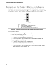
.../subwoofer speakers to connector (C). ⎯ Using the audio driver interface, retask connector (A) to be Center/LFE Out. 40 Typical connector assignments are retaskable using the audio driver interface. The back panel audio connectors support up to be Rear Left/Right Out and retask connector (C) to six speakers and are shown in the table in Figure 19. Intel Desktop Board D915GVWB Product Guide Connecting to the Flexible 6-Channel Audio System Installing the audio driver from the Intel Express Installer CD-ROM enables the...
.../subwoofer speakers to connector (C). ⎯ Using the audio driver interface, retask connector (A) to be Center/LFE Out. 40 Typical connector assignments are retaskable using the audio driver interface. The back panel audio connectors support up to be Rear Left/Right Out and retask connector (C) to six speakers and are shown in the table in Figure 19. Intel Desktop Board D915GVWB Product Guide Connecting to the Flexible 6-Channel Audio System Installing the audio driver from the Intel Express Installer CD-ROM enables the...
English Product Guide
Page 45
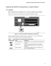
...pin BIOS jumper block enables all board configurations to clear passwords. 1 3 Recovery (None) The BIOS recovers data from the computer before changing the jumper. Table 8 shows the jumper settings for booting. 1 3 Configure (2-3) After the Power-On Self-Test (POST) runs, the BIOS displays the Maintenance Menu. Table 8. Jumper Settings for the BIOS Setup Program Modes Jumper Setting Mode Description 1 3 Normal (default) (1-2) The BIOS uses the current configuration and passwords for the Setup program modes. Installing and Replacing Desktop Board Components Setting the BIOS...
...pin BIOS jumper block enables all board configurations to clear passwords. 1 3 Recovery (None) The BIOS recovers data from the computer before changing the jumper. Table 8 shows the jumper settings for booting. 1 3 Configure (2-3) After the Power-On Self-Test (POST) runs, the BIOS displays the Maintenance Menu. Table 8. Jumper Settings for the BIOS Setup Program Modes Jumper Setting Mode Description 1 3 Normal (default) (1-2) The BIOS uses the current configuration and passwords for the Setup program modes. Installing and Replacing Desktop Board Components Setting the BIOS...


