
Product Guide
Page 16
... a password. Intel Desktop Boards D845HV and D845WN Product Guide IDE Auto Configuration If you install an IDE device (such as a hard drive) in your computer. To use ATA-66/100 features, the following functions: • Basic 10/100 Ethernet LAN connectivity • Supports RJ-45 connector with status indicator LEDs • Programmable transit threshold • Configurable EEPROM that restrict whether the BIOS Setup program can be set for the Setup and for your computer, the IDE auto-configuration utility...
... a password. Intel Desktop Boards D845HV and D845WN Product Guide IDE Auto Configuration If you install an IDE device (such as a hard drive) in your computer. To use ATA-66/100 features, the following functions: • Basic 10/100 Ethernet LAN connectivity • Supports RJ-45 connector with status indicator LEDs • Programmable transit threshold • Configurable EEPROM that restrict whether the BIOS Setup program can be set for the Setup and for your computer, the IDE auto-configuration utility...
Product Guide
Page 37
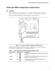
... Jumper Settings for the BIOS Setup Program Modes (J9G1) Function / Mode Normal Configure Jumper Setting 1-2 1 3 2-3 1 3 Configuration The BIOS uses current configuration information and passwords for the Setup program modes. Recovery None 1 3 The BIOS attempts to clear passwords. Installing and Replacing Desktop Board Components Setting the BIOS Configuration Jumper Block CAUTION Always turn off the power and unplug the power cord from the computer before changing the jumper. Table 5. Table 5 shows the jumper settings for booting. After the POST runs, the BIOS displays...
... Jumper Settings for the BIOS Setup Program Modes (J9G1) Function / Mode Normal Configure Jumper Setting 1-2 1 3 2-3 1 3 Configuration The BIOS uses current configuration information and passwords for the Setup program modes. Recovery None 1 3 The BIOS attempts to clear passwords. Installing and Replacing Desktop Board Components Setting the BIOS Configuration Jumper Block CAUTION Always turn off the power and unplug the power cord from the computer before changing the jumper. Table 5. Table 5 shows the jumper settings for booting. After the POST runs, the BIOS displays...
Product Guide
Page 38
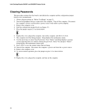
... devices connected to the computer. Find the configuration jumper block (see Figure 17). 5. Place the jumper on pins 2-3 as shown below . 1 3 6. Setup displays the maintenance menu again. 9. Replace the cover, plug in the computer and the configuration jumper block is set to boot. 7. Intel Desktop Boards D845HV and D845WN Product Guide Clearing Passwords This procedure assumes that you confirm clearing the password. Turn off the computer. Setup displays the maintenance menu. 8. Remove the computer cover. 12. Disconnect the computer's power...
... devices connected to the computer. Find the configuration jumper block (see Figure 17). 5. Place the jumper on pins 2-3 as shown below . 1 3 6. Setup displays the maintenance menu again. 9. Replace the cover, plug in the computer and the configuration jumper block is set to boot. 7. Intel Desktop Boards D845HV and D845WN Product Guide Clearing Passwords This procedure assumes that you confirm clearing the password. Turn off the computer. Setup displays the maintenance menu. 8. Remove the computer cover. 12. Disconnect the computer's power...
Product Guide
Page 47
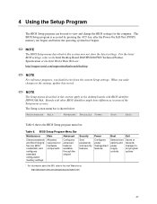
... the chipset Security Sets passwords and security features Power Configures power management features Boot Selects boot options and power supply controls Exit Saves or discards changes to set program options * For information about the BIS, refer to the Intel Web site at: http://developer.intel.com/design/security/index1.htm 47 Boards with BIOS identifier HV84510A.86A. The Setup screen menu bar is accessed by pressing the key after the Power-On Self-Test (POST) memory test...
... the chipset Security Sets passwords and security features Power Configures power management features Boot Selects boot options and power supply controls Exit Saves or discards changes to set program options * For information about the BIS, refer to the Intel Web site at: http://developer.intel.com/design/security/index1.htm 47 Boards with BIOS identifier HV84510A.86A. The Setup screen menu bar is accessed by pressing the key after the Power-On Self-Test (POST) memory test...
Product Guide
Page 49
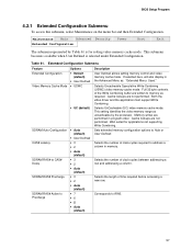
... Menu: Used." Selects UnCacheable (UC) video memory cache mode. Cache lookups are written to memory as uncacheable by the processor. This setting identifies the video memory range as required. Sets extended memory configuration options to CAS# Delay SDRAM RAS# Precharge Options • Default (default) • User-Defined • USWC • UC (default) • Auto (default) • User Defined • 3 • 2 • Auto (default) • 3 • 2 • Auto (default) • 3 • 2 • Auto (default) Description User Defined allows setting memory...
... Menu: Used." Selects UnCacheable (UC) video memory cache mode. Cache lookups are written to memory as uncacheable by the processor. This setting identifies the video memory range as required. Sets extended memory configuration options to CAS# Delay SDRAM RAS# Precharge Options • Default (default) • User-Defined • USWC • UC (default) • Auto (default) • User Defined • 3 • 2 • Auto (default) • 3 • 2 • Auto (default) • 3 • 2 • Auto (default) Description User Defined allows setting memory...

Product Guide
Page 50
... current default language used to configure the system date and system time. This menu reports processor and memory information and is ECC-capable. Displays processor speed. Displays the size of second-level cache and whether it is used by the BIOS. • Espanol • Disabled (default) Enables and disables the processor serial number. • Enabled Hour, minute, and second Specifies the current time. Intel Desktop Boards D845HV and D845WN Product Guide Main Menu Maintenance Main Advanced Security Power Boot Exit...
... current default language used to configure the system date and system time. This menu reports processor and memory information and is ECC-capable. Displays processor speed. Displays the size of second-level cache and whether it is used by the BIOS. • Espanol • Disabled (default) Enables and disables the processor serial number. • Enabled Hour, minute, and second Specifies the current time. Intel Desktop Boards D845HV and D845WN Product Guide Main Menu Maintenance Main Advanced Security Power Boot Exit...
Product Guide
Page 55
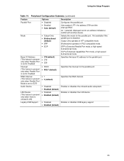
... operates in AT†-compatible mode. EPP is Enhanced Capabilities Port mode, a high-speed bi-directional mode. Specifies the DMA channel. Selects the mode for the parallel port. ECP is Extended Parallel Port mode, a high-speed bi-directional mode. Auto assigns LPT1 the address 378h and the interrupt IRQ7. Enables or disables USB legacy support. 55 Enables or disables the onboard audio subsystem. Not available if the parallel port is onboard LAN) Legacy USB Support Options • Disabled • Enabled • Auto (default) • Output Only...
... operates in AT†-compatible mode. EPP is Enhanced Capabilities Port mode, a high-speed bi-directional mode. Specifies the DMA channel. Selects the mode for the parallel port. ECP is Extended Parallel Port mode, a high-speed bi-directional mode. Auto assigns LPT1 the address 378h and the interrupt IRQ7. Enables or disables USB legacy support. 55 Enables or disables the onboard audio subsystem. Not available if the parallel port is onboard LAN) Legacy USB Support Options • Disabled • Enabled • Auto (default) • Output Only...
Product Guide
Page 57
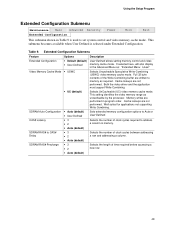
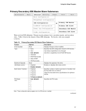
... IDE configuration mode for optimum setting. User allows capabilities to memory. Note: These configuration options appear only if an IDE device is shown. Enables or disables LBA mode control. For brevity, only one example is installed. Specifies number of these IDE submenus. Using the Setup Program Primary/Secondary IDE Master/Slave Submenus Maintenance Main Advanced Security Boot Configuration Power Boot Exit Peripheral Configuration IDE Configuration Diskette Configuration ➜ Primary IDE Master Primary IDE Slave Event Log Configuration Secondary IDE Master Video...
... IDE configuration mode for optimum setting. User allows capabilities to memory. Note: These configuration options appear only if an IDE device is shown. Enables or disables LBA mode control. For brevity, only one example is installed. Specifies number of these IDE submenus. Using the Setup Program Primary/Secondary IDE Master/Slave Submenus Maintenance Main Advanced Security Boot Configuration Power Boot Exit Peripheral Configuration IDE Configuration Diskette Configuration ➜ Primary IDE Master Primary IDE Slave Event Log Configuration Secondary IDE Master Video...
Product Guide
Page 61
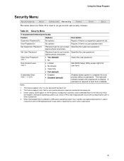
... (default) Clears the user password. • No • Limited • No Access Sets BIOS Setup Utility access rights for user level. • View Only • Full (default) • Enabled • Disabled (default) Enabled allows system to complete the boot process without requiring the user to seven Specifies the supervisor password. When Unattended Start is enabled, a USB aware operating system may override user password protection if used to boot from a diskette. Using the Setup Program Security Menu Maintenance Main Advanced Security Power Boot...
... (default) Clears the user password. • No • Limited • No Access Sets BIOS Setup Utility access rights for user level. • View Only • Full (default) • Enabled • Disabled (default) Enabled allows system to complete the boot process without requiring the user to seven Specifies the supervisor password. When Unattended Start is enabled, a USB aware operating system may override user password protection if used to boot from a diskette. Using the Setup Program Security Menu Maintenance Main Advanced Security Power Boot...

Product Guide
Page 63
... Scan User Flash Area Boot Device Priority Hard Disk Drives Removable Devices Options • Disabled • Enabled (default) • Disabled • Enabled (default) • Disabled (default) • Enabled No options No options No options Description Disabled displays normal POST messages. Enables the BIOS to set the boot features and the boot sequence. Specifies the boot sequence from the available types of POST messages. Specifies the boot sequence from the available removable devices. Using the Setup Program Boot Menu Maintenance Main Advanced Security Power Boot...
... Scan User Flash Area Boot Device Priority Hard Disk Drives Removable Devices Options • Disabled • Enabled (default) • Disabled • Enabled (default) • Disabled (default) • Enabled No options No options No options Description Disabled displays normal POST messages. Enables the BIOS to set the boot features and the boot sequence. Specifies the boot sequence from the available types of POST messages. Specifies the boot sequence from the available removable devices. Using the Setup Program Boot Menu Maintenance Main Advanced Security Power Boot...

Product Guide
Page 64
... Network Device Interface), PXE device. Notes: 1. Select the boot device with respect to each boot device in the order listed. Changing the order of boot • Hard Drive devices. After the predefined boot device types (removable devices, hard drives, and ATAPI CD-ROM drives), the entries in this level. 64 For example, assume that seven boot devices of five) (Note 2). Intel Desktop Boards D845HV and D845WN Product Guide Boot Device Priority Submenu Maintenance Main Advanced Security Power Boot Exit Boot Device Priority Hard Disk Drives Removable Devices...
... Network Device Interface), PXE device. Notes: 1. Select the boot device with respect to each boot device in the order listed. Changing the order of boot • Hard Drive devices. After the predefined boot device types (removable devices, hard drives, and ATAPI CD-ROM drives), the entries in this level. 64 For example, assume that seven boot devices of five) (Note 2). Intel Desktop Boards D845HV and D845WN Product Guide Boot Device Priority Submenu Maintenance Main Advanced Security Power Boot Exit Boot Device Priority Hard Disk Drives Removable Devices...
Product Specification
Page 8
... the Jumper Block 72 17. Specifications ...18 5. Supported Processors 21 6. LAN Connector (optional 54 23. Auxiliary Line In Connector (Optional 57 28. Back Panel Connectors 52 11. Localized High Temperature Zones 82 Tables 1. LAN Connector LED States 34 8. PCI Configuration Space Map 48 16. PCI Interrupt Routing Map 50 18. PS/2 Mouse/Keyboard Connector 53 19. Audio Line In Connector (Optional 54 24. Mic In Connector (Optional 54 26. Chassis Intrusion Connector 60 viii Audio Connectors ...56 12. D845HV Add-in Board...
... the Jumper Block 72 17. Specifications ...18 5. Supported Processors 21 6. LAN Connector (optional 54 23. Auxiliary Line In Connector (Optional 57 28. Back Panel Connectors 52 11. Localized High Temperature Zones 82 Tables 1. LAN Connector LED States 34 8. PCI Configuration Space Map 48 16. PCI Interrupt Routing Map 50 18. PS/2 Mouse/Keyboard Connector 53 19. Audio Line In Connector (Optional 54 24. Mic In Connector (Optional 54 26. Chassis Intrusion Connector 60 viii Audio Connectors ...56 12. D845HV Add-in Board...
Product Specification
Page 27
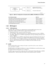
... is device driver compatible. • ATA-100: DMA protocol on the back panel The signal names of the back panel USB connectors The location of the front panel USB connector The signal names of the USB connectors on IDE bus allows host and target throttling. The drive reports the transfer rate and translation mode to the audio connectors USB ports (2) Front panel USB connector OM12389 Figure 6. USB Port Configuration for Boards with the SMSC LPC47M132 I /O Controller Hub (ICH2) USB USB ports (2) Back panel USB connectors...
... is device driver compatible. • ATA-100: DMA protocol on the back panel The signal names of the back panel USB connectors The location of the front panel USB connector The signal names of the USB connectors on IDE bus allows host and target throttling. The drive reports the transfer rate and translation mode to the audio connectors USB ports (2) Front panel USB connector OM12389 Figure 6. USB Port Configuration for Boards with the SMSC LPC47M132 I /O Controller Hub (ICH2) USB USB ports (2) Back panel USB connectors...
Product Specification
Page 28
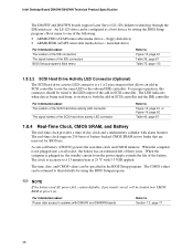
Intel Desktop Board D845HV/D845WN Technical Product Specification The D845HV and D845WN boards support Laser Servo (LS-120) diskette technology through the IDE interfaces. A coin-cell battery (CR2032) powers the real-time clock and CMOS memory. For proper operation, this connector should be configured as the onboard IDE controller. When the computer is not plugged into CMOS RAM at 25 ºC with D845HV and D845WN boards Refer to , both the add-in the BIOS Setup program. The time...
Intel Desktop Board D845HV/D845WN Technical Product Specification The D845HV and D845WN boards support Laser Servo (LS-120) diskette technology through the IDE interfaces. A coin-cell battery (CR2032) powers the real-time clock and CMOS memory. For proper operation, this connector should be configured as the onboard IDE controller. When the computer is not plugged into CMOS RAM at 25 ºC with D845HV and D845WN boards Refer to , both the add-in the BIOS Setup program. The time...
Product Specification
Page 35
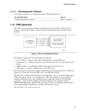
...-channel audio using a CNR audio upgrade card in multiple configurations from Intel's World Wide Web site. Product Description 1.11.3 LAN Subsystem Software LAN software and drivers are available from several different vendors supporting analog or S/P-DIF digital connections. The CNR connector includes power signals required for power management and for the CNR board. CNR Connector Intel 82801BA I/O Controller Hub (ICH2) AC '97 Interface LAN Interface SMBus USB Communication and Networking Riser (Up to the CNR specification. A list...
...-channel audio using a CNR audio upgrade card in multiple configurations from Intel's World Wide Web site. Product Description 1.11.3 LAN Subsystem Software LAN software and drivers are available from several different vendors supporting analog or S/P-DIF digital connections. The CNR connector includes power signals required for power management and for the CNR board. CNR Connector Intel 82801BA I/O Controller Hub (ICH2) AC '97 Interface LAN Interface SMBus USB Communication and Networking Riser (Up to the CNR specification. A list...
Product Specification
Page 88
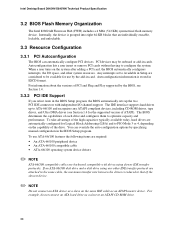
... onboard or add-in cards. The BIOS determines the capabilities of PCI and Plug and Play supported by specifying manual configuration in ESCD format. If an ATA-66/100 disk drive and a disk drive using slower IDE transfer protocols. For information about the versions of each drive and configures them to configure the system. Intel Desktop Board D845HV/D845WN Technical Product Specification 3.2 BIOS Flash Memory Organization The Intel 82802AB Firmware Hub (FWH) includes a 4 Mbit (512 KB) symmetrical flash memory device. Internally, the device...
... onboard or add-in cards. The BIOS determines the capabilities of PCI and Plug and Play supported by specifying manual configuration in ESCD format. If an ATA-66/100 disk drive and a disk drive using slower IDE transfer protocols. For information about the versions of each drive and configures them to configure the system. Intel Desktop Board D845HV/D845WN Technical Product Specification 3.2 BIOS Flash Memory Organization The Intel 82802AB Firmware Hub (FWH) includes a 4 Mbit (512 KB) symmetrical flash memory device. Internally, the device...
Product Specification
Page 95
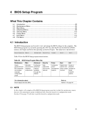
... Main Menu...98 4.4 Advanced Menu...99 4.5 Security Menu ...110 4.6 Power Menu ...111 4.7 Boot Menu ...113 4.8 Exit Menu ...117 4.1 Introduction The BIOS Setup program can be used to view and change the BIOS settings for hardware components Configures advanced features available through the chipset Sets passwords and security features Power Boot Exit Configures power management features Selects boot options and power supply controls Saves or discards changes to Setup program options For information about Boot Integrity Services (BIS) Refer to put the board in configuration mode...
... Main Menu...98 4.4 Advanced Menu...99 4.5 Security Menu ...110 4.6 Power Menu ...111 4.7 Boot Menu ...113 4.8 Exit Menu ...117 4.1 Introduction The BIOS Setup program can be used to view and change the BIOS settings for hardware components Configures advanced features available through the chipset Sets passwords and security features Power Boot Exit Configures power management features Selects boot options and power supply controls Saves or discards changes to Setup program options For information about Boot Integrity Services (BIS) Refer to put the board in configuration mode...
Product Specification
Page 97
...; Auto (default) User Defined allows setting memory control and video memory cache mode. Cache lookups are not performed. Selects Uncacheable Speculative Write-Combining (USWC) video memory cache mode. This setting identifies the video memory range as uncacheable by Table 61 is selected under Extended Configuration. Maintenance Main Advanced Security Extended Configuration Power Boot Exit The submenu represented by the processor. This submenu becomes available when User Defined is for applications not supporting Write...
...; Auto (default) User Defined allows setting memory control and video memory cache mode. Cache lookups are not performed. Selects Uncacheable Speculative Write-Combining (USWC) video memory cache mode. This setting identifies the video memory range as uncacheable by Table 61 is selected under Extended Configuration. Maintenance Main Advanced Security Extended Configuration Power Boot Exit The submenu represented by the processor. This submenu becomes available when User Defined is for applications not supporting Write...
Product Specification
Page 104
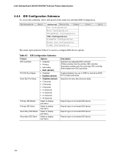
... Log Configuration Video Configuration Boot Exit The menu represented in Table 67 is used to display sub-menu Description Specifies the integrated IDE controller. Table 67. Enables/disables the use of connected IDE device. Reports type of DMA for hard drive BIOS INT13 reads and writes. Reports type of connected IDE device. Both enables both IDE controllers. Reports type of connected IDE device. Secondary enables only the secondary IDE controller. Reports type of connected IDE device. 104 Specifies the hard disk drive pre-delay. Intel Desktop Board D845HV/D845WN...
... Log Configuration Video Configuration Boot Exit The menu represented in Table 67 is used to display sub-menu Description Specifies the integrated IDE controller. Table 67. Enables/disables the use of connected IDE device. Reports type of DMA for hard drive BIOS INT13 reads and writes. Reports type of connected IDE device. Both enables both IDE controllers. Reports type of connected IDE device. Secondary enables only the secondary IDE controller. Reports type of connected IDE device. 104 Specifies the hard disk drive pre-delay. Intel Desktop Board D845HV/D845WN...
Product Specification
Page 121
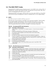
.... Do necessary chipset initialization, start memory refresh, and do memory sizing. Uncompress the main BIOS module. Copy main BIOS image to F000 shadow RAM and give control to segment 0. Initialize extra (Intel Recovery) Module. Table 83. Init code to be copied to segment 0 and control to be installed in ROM image. Table 82. Displaying the POST-codes requires a PCI bus add-in F000 shadow RAM. The POST card can decode the port and display the contents on...
.... Do necessary chipset initialization, start memory refresh, and do memory sizing. Uncompress the main BIOS module. Copy main BIOS image to F000 shadow RAM and give control to segment 0. Initialize extra (Intel Recovery) Module. Table 83. Init code to be copied to segment 0 and control to be installed in ROM image. Table 82. Displaying the POST-codes requires a PCI bus add-in F000 shadow RAM. The POST card can decode the port and display the contents on...


