
Product Guide
Page 2
... between the equipment and the receiver. • Connect the equipment to an outlet on a circuit other Intel literature, may be claimed as the property of the Intel® Desktop Boards D845HV and D845WN Product Guide. Copyright © 2001, Intel Corporation. Revision History Revision -001 Revision History First release of others. These limits are trademarks or...
... between the equipment and the receiver. • Connect the equipment to an outlet on a circuit other Intel literature, may be claimed as the property of the Intel® Desktop Boards D845HV and D845WN Product Guide. Copyright © 2001, Intel Corporation. Revision History Revision -001 Revision History First release of others. These limits are trademarks or...
Product Guide
Page 3
Contents 1 Desktop Board Features Components...9 Processor ...11 Main Memory ...11 Intel® 845 Chipset ...12 Intel® 82845 Memory Controller Hub (MCH 12 Intel® 82801BA I/O Controller Hub (ICH2 13 Firmware Hub (FWH 13 Input/Output (I/O) Controller 13 Real-Time ...Management Features 17 Resume on Ring...18 Instantly Available Technology 18 2 Installing and Replacing Desktop Board Components Before You Begin ...21 Installing the I/O Shield ...22 Installing and Removing the Desktop Board 23 Installing and Removing a Processor 25 Installing the Processor Fan Heatsink Retention ...
Contents 1 Desktop Board Features Components...9 Processor ...11 Main Memory ...11 Intel® 845 Chipset ...12 Intel® 82845 Memory Controller Hub (MCH 12 Intel® 82801BA I/O Controller Hub (ICH2 13 Firmware Hub (FWH 13 Input/Output (I/O) Controller 13 Real-Time ...Management Features 17 Resume on Ring...18 Instantly Available Technology 18 2 Installing and Replacing Desktop Board Components Before You Begin ...21 Installing the I/O Shield ...22 Installing and Removing the Desktop Board 23 Installing and Removing a Processor 25 Installing the Processor Fan Heatsink Retention ...
Product Guide
Page 4
Intel Desktop Boards D845HV and D845WN Product Guide Installing and Removing Memory 29 DIMM Installation Guidelines 29 Installing DIMMs ...29 Removing DIMMs ...31 Installing and Removing the AGP Retention ... Configuration Jumper Block 37 Clearing Passwords ...38 Replacing the Battery ...39 3 Updating the BIOS Updating the BIOS with the Intel® Express BIOS Update Utility 43 Updating the BIOS with the Intel® Flash Memory Update Utility 44 Obtaining the BIOS Update File 44 Updating the BIOS...44 Recovering the BIOS 45...
Intel Desktop Boards D845HV and D845WN Product Guide Installing and Removing Memory 29 DIMM Installation Guidelines 29 Installing DIMMs ...29 Removing DIMMs ...31 Installing and Removing the AGP Retention ... Configuration Jumper Block 37 Clearing Passwords ...38 Replacing the Battery ...39 3 Updating the BIOS Updating the BIOS with the Intel® Express BIOS Update Utility 43 Updating the BIOS with the Intel® Flash Memory Update Utility 44 Obtaining the BIOS Update File 44 Updating the BIOS...44 Recovering the BIOS 45...

Product Guide
Page 5
...9. Back Panel Connectors 68 20. Contents 5 Technical Reference Board Connectors ...67 Back Panel Connectors 68 Midboard Connectors 69 Front Panel Connectors 73 Desktop Board Resources 74 Memory Map ...74 DMA Channels ...74 I /O Shield 22 5. Installing a Processor...27 10. Installing the AGP Card ... Mechanism 33 14. Removing the AGP Card 34 15. Removing the AGP Card Retention Mechanism 35 16. Connecting the IDE Cable 36 17. D845HV Board Components 9 2. Installing the I /O Map ...75 Interrupts ...77 A Error Messages and Indicators BIOS Beep Codes ...79 BIOS Error Messages...
...9. Back Panel Connectors 68 20. Contents 5 Technical Reference Board Connectors ...67 Back Panel Connectors 68 Midboard Connectors 69 Front Panel Connectors 73 Desktop Board Resources 74 Memory Map ...74 DMA Channels ...74 I /O Shield 22 5. Installing a Processor...27 10. Installing the AGP Card ... Mechanism 33 14. Removing the AGP Card 34 15. Removing the AGP Card Retention Mechanism 35 16. Connecting the IDE Cable 36 17. D845HV Board Components 9 2. Installing the I /O Map ...75 Interrupts ...77 A Error Messages and Indicators BIOS Beep Codes ...79 BIOS Error Messages...

Product Guide
Page 6
Intel Desktop Boards D845HV and D845WN Product Guide 21. D845WN Board Add-in Card and Peripheral Interface Connectors 71 23. Processors Supported by the Desktop Board 11 3. BIOS Setup Program Menu Bar 47 7. Extended Configuration Submenu 49 10. Peripheral Configuration Submenu 54 15. Event...56 16. Security Menu...61 21. Beep Codes ...79 34. ATAPI CD-ROM Drives Submenu 66 28. Safety Regulations...83 36. D845HV Board Add-in Card and Peripheral Interface Connectors 72 24. Video Configuration Submenu 60 20. BIOS Setup Program Function Keys 48 8. Main ...
Intel Desktop Boards D845HV and D845WN Product Guide 21. D845WN Board Add-in Card and Peripheral Interface Connectors 71 23. Processors Supported by the Desktop Board 11 3. BIOS Setup Program Menu Bar 47 7. Extended Configuration Submenu 49 10. Peripheral Configuration Submenu 54 15. Event...56 16. Security Menu...61 21. Beep Codes ...79 34. ATAPI CD-ROM Drives Submenu 66 28. Safety Regulations...83 36. D845HV Board Add-in Card and Peripheral Interface Connectors 72 24. Video Configuration Submenu 60 20. BIOS Setup Program Function Keys 48 8. Main ...
Product Guide
Page 7
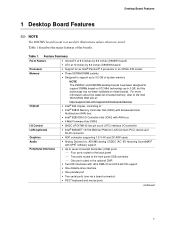
...) • ATX at 12 inches by 9.6 inches (D845WN board) • Support for illustrations unless otherwise noted. Desktop Board Features 1 Desktop Board Features ✏ NOTE The D845HV board layout was used for an Intel® Pentium® 4 processor in an mPGA-478 socket • Three SDRAM DIMM sockets. • Designed to support up to 3.0 GB...
...) • ATX at 12 inches by 9.6 inches (D845WN board) • Support for illustrations unless otherwise noted. Desktop Board Features 1 Desktop Board Features ✏ NOTE The D845HV board layout was used for an Intel® Pentium® 4 processor in an mPGA-478 socket • Three SDRAM DIMM sockets. • Designed to support up to 3.0 GB...
Product Guide
Page 8
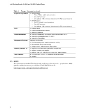
Intel Desktop Boards D845HV and D845WN Product Guide Table 1. Feature Summary (continued) Expansion Capabilities • D845HV board: Three PCI bus add-in card connectors &#...63719; One AGP connector One optional CNR connector (slot shared with PCI bus connector 6) BIOS • Intel/AMI BIOS. • 4 Mbit symmetrical flash memory • Support for SMBIOS Power Management • Support for Advanced... • Speaker ✏ NOTE For information about Intel® desktop boards, including technical product specifications, BIOS updates, and device drivers, go to the...
Intel Desktop Boards D845HV and D845WN Product Guide Table 1. Feature Summary (continued) Expansion Capabilities • D845HV board: Three PCI bus add-in card connectors &#...63719; One AGP connector One optional CNR connector (slot shared with PCI bus connector 6) BIOS • Intel/AMI BIOS. • 4 Mbit symmetrical flash memory • Support for SMBIOS Power Management • Support for Advanced... • Speaker ✏ NOTE For information about Intel® desktop boards, including technical product specifications, BIOS updates, and device drivers, go to the...
Product Guide
Page 9
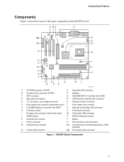
Desktop Board Features Components Figure 1 shows the location of the major components on the D845HV board. D845HV Board Components 9 A BC D BB E F AA G Z H Y X I W J V K U T SQ N R PO ML OM11978 A CD-ROM connector (ATAPI) O Secondary IDE connector B Auxiliary line-in connector (ATAPI) P Speaker C AGP connector Q Intel... connector S Chassis intrusion connector F Rear chassis fan connector (tachometer input) T Front chassis fan connector G Intel 82845 Memory Controller Hub (MCH) U Alternate power/sleep LED connector H Processor socket V Front panel connector...
Desktop Board Features Components Figure 1 shows the location of the major components on the D845HV board. D845HV Board Components 9 A BC D BB E F AA G Z H Y X I W J V K U T SQ N R PO ML OM11978 A CD-ROM connector (ATAPI) O Secondary IDE connector B Auxiliary line-in connector (ATAPI) P Speaker C AGP connector Q Intel... connector S Chassis intrusion connector F Rear chassis fan connector (tachometer input) T Front chassis fan connector G Intel 82845 Memory Controller Hub (MCH) U Alternate power/sleep LED connector H Processor socket V Front panel connector...

Product Guide
Page 10
...Intel Desktop Boards D845HV and D845WN Product Guide Figure 2 shows the location of the major components on the D845WN board. A BC D BB E F AA G Z H Y X I W J V K U T SQ N R PO ML OM12039 A CD-ROM connector (ATAPI) O Secondary IDE connector B Auxiliary line-in connector (ATAPI) P Speaker C AGP connector Q Intel... voltage connector S Chassis intrusion connector F Rear chassis fan connector (tachometer input) T Front chassis fan connector G Intel 82845 Memory Controller Hub (MCH) U Alternate power/sleep LED connector H Processor socket V Front panel connector I ...
...Intel Desktop Boards D845HV and D845WN Product Guide Figure 2 shows the location of the major components on the D845WN board. A BC D BB E F AA G Z H Y X I W J V K U T SQ N R PO ML OM12039 A CD-ROM connector (ATAPI) O Secondary IDE connector B Auxiliary line-in connector (ATAPI) P Speaker C AGP connector Q Intel... voltage connector S Chassis intrusion connector F Rear chassis fan connector (tachometer input) T Front chassis fan connector G Intel 82845 Memory Controller Hub (MCH) U Alternate power/sleep LED connector H Processor socket V Front panel connector I ...
Product Guide
Page 11
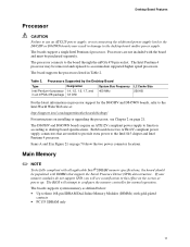
...memory as defined below: • Up to the desktop board and/or power supply. If your memory modules do not support SPD, you will attempt to configure the memory controller for the D845HV and D845WN boards, refer to the Intel World Wide Web site at power up. Processors are... needed to provide extra power to this effect on the screen at : http://support.intel.com/support/motherboards/desktop/ For instructions on processor support for normal ...
...memory as defined below: • Up to the desktop board and/or power supply. If your memory modules do not support SPD, you will attempt to configure the memory controller for the D845HV and D845WN boards, refer to the Intel World Wide Web site at power up. Processors are... needed to provide extra power to this effect on the screen at : http://support.intel.com/support/motherboards/desktop/ For instructions on processor support for normal ...

Product Guide
Page 12
...; 82845 Memory Controller Hub (MCH) The MCH provides the processor, system memory, AGP, and hub interfaces in the Intel 845 chipset platform. Intel Desktop Boards D845HV and D845WN Product Guide • 64 Mbit, 128 Mbit, and 256 Mbit technologies for up to 1.5 GB (with 4X...more information about installing memory, see Chapter 2 starting on these memory requirements, refer to the D845HV or D845WN link on this Intel World Wide Web site: http://support.intel.com/support/motherboards/desktop/ For information about the latest list of the following memory configurations: 32 MB to...
...; 82845 Memory Controller Hub (MCH) The MCH provides the processor, system memory, AGP, and hub interfaces in the Intel 845 chipset platform. Intel Desktop Boards D845HV and D845WN Product Guide • 64 Mbit, 128 Mbit, and 256 Mbit technologies for up to 1.5 GB (with 4X...more information about installing memory, see Chapter 2 starting on these memory requirements, refer to the D845HV or D845WN link on this Intel World Wide Web site: http://support.intel.com/support/motherboards/desktop/ For information about the latest list of the following memory configurations: 32 MB to...

Product Guide
Page 13
...D845HV and D845WN boards includes: • Integrated IDE controller supports two Ultra DMA-33 and ATA-66/100 channels, BMIDE and PIO modes • SMBus interface • FWH interface • Low Pin Count (LPC) interface • AC'97 2.1 compliant link for audio and telephony CODECs • Integrated Intel... inputs Real-Time Clock The desktop boards have a time-of the platform. ICH2 features on the desktop board keeps the clock current when the computer is turned off. 13 Desktop Board Features Intel® 82801BA I/O Controller Hub (ICH2) The Intel 82801BA I/O Controller Hub integrates ...
...D845HV and D845WN boards includes: • Integrated IDE controller supports two Ultra DMA-33 and ATA-66/100 channels, BMIDE and PIO modes • SMBus interface • FWH interface • Low Pin Count (LPC) interface • AC'97 2.1 compliant link for audio and telephony CODECs • Integrated Intel... inputs Real-Time Clock The desktop boards have a time-of the platform. ICH2 features on the desktop board keeps the clock current when the computer is turned off. 13 Desktop Board Features Intel® 82801BA I/O Controller Hub (ICH2) The Intel 82801BA I/O Controller Hub integrates ...

Product Guide
Page 14
...; One AGP connector • One optional CNR connector (slot shared with UHCI. The interface supports: • Up to the optional CNR. Intel Desktop Boards D845HV and D845WN Product Guide USB Support ✏ NOTE Computer systems that meets the requirements for a full-speed USB device. Use a shielded cable ...that have the following add-in card connectors: The D845HV board has: • Three PCI bus add-in card connectors (PCI bus connector 3 slot shared with CNR) • One AGP connector &#...
...; One AGP connector • One optional CNR connector (slot shared with UHCI. The interface supports: • Up to the optional CNR. Intel Desktop Boards D845HV and D845WN Product Guide USB Support ✏ NOTE Computer systems that meets the requirements for a full-speed USB device. Use a shielded cable ...that have the following add-in card connectors: The D845HV board has: • Three PCI bus add-in card connectors (PCI bus connector 3 slot shared with CNR) • One AGP connector &#...

Product Guide
Page 15
.... PCI Auto Configuration If you install a PCI add-in cards. You do not need to this output. Desktop Board Features Accelerated Graphics Port (AGP) ✏ NOTE The D845HV and D845WN boards are only compatible with retention notches (see Chapter 2 on page 43. Poor audio quality may... occur if passive (non-amplified) speakers are available from Intel's World Wide Web site: http://support.intel.com/support/motherboards/desktop/ BIOS The BIOS provides ...
.... PCI Auto Configuration If you install a PCI add-in cards. You do not need to this output. Desktop Board Features Accelerated Graphics Port (AGP) ✏ NOTE The D845HV and D845WN boards are only compatible with retention notches (see Chapter 2 on page 43. Poor audio quality may... occur if passive (non-amplified) speakers are available from Intel's World Wide Web site: http://support.intel.com/support/motherboards/desktop/ BIOS The BIOS provides ...
Product Guide
Page 16
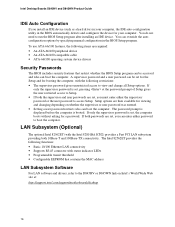
If only the supervisor password is set, pressing at : http://support.intel.com/support/motherboards/desktop 16 If both 10Base-T and 100Base-TX connectivity. The password prompt is displayed before the computer is set for the Setup and for booting ...8226; Programmable transit threshold • Configurable EEPROM that restrict whether the BIOS Setup program can be set , the computer boots without asking for a password. Intel Desktop Boards D845HV and D845WN Product Guide IDE Auto Configuration If you install an IDE device (such as a hard drive) in your computer. To use ATA-66/100...
If only the supervisor password is set, pressing at : http://support.intel.com/support/motherboards/desktop 16 If both 10Base-T and 100Base-TX connectivity. The password prompt is displayed before the computer is set for the Setup and for booting ...8226; Programmable transit threshold • Configurable EEPROM that restrict whether the BIOS Setup program can be set , the computer boots without asking for a password. Intel Desktop Boards D845HV and D845WN Product Guide IDE Auto Configuration If you install an IDE device (such as a hard drive) in your computer. To use ATA-66/100...
Product Guide
Page 17
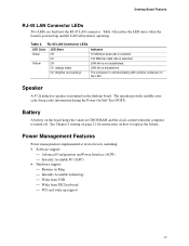
... in CMOS RAM and the clock current when the computer is operating. Table 3 describes the LED states when the board is mounted on the desktop board. Yellow Off LAN link is selected. RJ-45 LAN Connector LEDs LED Color LED State Indicates Green Off 10 Mbit/sec data rate is... not established. Battery A battery on how to replace the battery. Desktop Board Features RJ-45 LAN Connector LEDs Two LEDs are built into the RJ-45 LAN connector. Speaker A 47 Ω inductive speaker is powered up...
... in CMOS RAM and the clock current when the computer is operating. Table 3 describes the LED states when the board is mounted on the desktop board. Yellow Off LAN link is selected. RJ-45 LAN Connector LEDs LED Color LED State Indicates Green Off 10 Mbit/sec data rate is... not established. Battery A battery on how to replace the battery. Desktop Board Features RJ-45 LAN Connector LEDs Two LEDs are built into the RJ-45 LAN connector. Speaker A 47 Ω inductive speaker is powered up...
Product Guide
Page 18
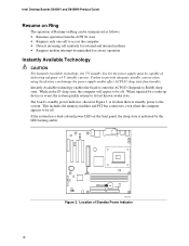
... only one call to be off . Instantly Available technology enables the board to enter the ACPI S3 (Suspend-to its last known awake state. Intel Desktop Boards D845HV and D845WN Product Guide Resume on Ring The operation of Resume on the front panel, the sleep state is standby power to be capable of...
... only one call to be off . Instantly Available technology enables the board to enter the ACPI S3 (Suspend-to its last known awake state. Intel Desktop Boards D845HV and D845WN Product Guide Resume on Ring The operation of Resume on the front panel, the sleep state is standby power to be capable of...

Product Guide
Page 19
...non-wake enabled) USB ports** Standby Current Requirements (mA) 770* 345 375 100 875 40 700 * Refer to the Intel Desktop Board D845HV/D845WN Technical Product Specification for a particular system configuration, standby current requirements of all additional wake-enabled devices' and nonwake-enabled ...enabled device is connected. 3. Actual measurements may lose register settings stored in memory. Note the total D845HV or D845WN board standby current requirement. 2. Desktop Board Features CAUTION If the standby current necessary to support multiple wake events from steps 1 through 5...
...non-wake enabled) USB ports** Standby Current Requirements (mA) 770* 345 375 100 875 40 700 * Refer to the Intel Desktop Board D845HV/D845WN Technical Product Specification for a particular system configuration, standby current requirements of all additional wake-enabled devices' and nonwake-enabled ...enabled device is connected. 3. Actual measurements may lose register settings stored in memory. Note the total D845HV or D845WN board standby current requirement. 2. Desktop Board Features CAUTION If the standby current necessary to support multiple wake events from steps 1 through 5...

Product Guide
Page 20
...; The USB ports are calculated by totaling the following : • One wake-enabled device @ 375 mA. • Five non wake-enabled devices @ 20 mA each. Intel Desktop Boards D845HV and D845WN Product Guide ✏ NOTE PCI requirements are limited to a combined total of 700 mA. 20
...; The USB ports are calculated by totaling the following : • One wake-enabled device @ 375 mA. • Five non wake-enabled devices @ 20 mA each. Intel Desktop Boards D845HV and D845WN Product Guide ✏ NOTE PCI requirements are limited to a combined total of 700 mA. 20
Product Guide
Page 21
... injury or equipment damage. Some circuitry on the board can result in this chapter. 2 Installing and Replacing Desktop Board Components This chapter tells you how to: • Install the I/O shield • Install and remove the desktop board • Install and remove a processor • Install and remove memory • Install and remove an...
... injury or equipment damage. Some circuitry on the board can result in this chapter. 2 Installing and Replacing Desktop Board Components This chapter tells you how to: • Install the I/O shield • Install and remove the desktop board • Install and remove a processor • Install and remove memory • Install and remove an...


