
Product Guide
Page 3
Contents 1 Desktop Board Features Components...9 Processor ...11 Main Memory ...11 Intel® 845 Chipset ...12 Intel® 82845 Memory Controller Hub (MCH 12 Intel® 82801BA I/O Controller Hub (ICH2 13 Firmware Hub (FWH 13 Input/Output (I/O) Controller 13 Real-Time Clock...13 USB Support ...14 PCI Enhanced IDE Interface ...
Contents 1 Desktop Board Features Components...9 Processor ...11 Main Memory ...11 Intel® 845 Chipset ...12 Intel® 82845 Memory Controller Hub (MCH 12 Intel® 82801BA I/O Controller Hub (ICH2 13 Firmware Hub (FWH 13 Input/Output (I/O) Controller 13 Real-Time Clock...13 USB Support ...14 PCI Enhanced IDE Interface ...
Product Guide
Page 4
Intel Desktop Boards D845HV and D845WN Product Guide Installing and Removing Memory 29 DIMM Installation Guidelines 29 Installing DIMMs ...29 Removing DIMMs ...31 Installing and Removing the AGP Retention Mechanism and Card 32 Installing the AGP Card ... Jumper Block 37 Clearing Passwords ...38 Replacing the Battery ...39 3 Updating the BIOS Updating the BIOS with the Intel® Express BIOS Update Utility 43 Updating the BIOS with the Intel® Flash Memory Update Utility 44 Obtaining the BIOS Update File 44 Updating the BIOS...44 Recovering the BIOS 45 4 Using the...
Intel Desktop Boards D845HV and D845WN Product Guide Installing and Removing Memory 29 DIMM Installation Guidelines 29 Installing DIMMs ...29 Removing DIMMs ...31 Installing and Removing the AGP Retention Mechanism and Card 32 Installing the AGP Card ... Jumper Block 37 Clearing Passwords ...38 Replacing the Battery ...39 3 Updating the BIOS Updating the BIOS with the Intel® Express BIOS Update Utility 43 Updating the BIOS with the Intel® Flash Memory Update Utility 44 Obtaining the BIOS Update File 44 Updating the BIOS...44 Recovering the BIOS 45 4 Using the...

Product Guide
Page 5
... 15. Removing the AGP Card Retention Mechanism 35 16. Location of Standby Power Indicator 18 4. Installing a Processor...27 10. D845HV Board Components 9 2. AGP Card with Retention Notch 32 13. Contents 5 Technical Reference Board Connectors ...67 Back Panel Connectors 68... Midboard Connectors 69 Front Panel Connectors 73 Desktop Board Resources 74 Memory Map ...74 DMA Channels ...74 I /O Shield 22 5. D845WN Board Components 10 3. D845HV Board Mounting Holes 23 6. Installing the I /O Map ...75 Interrupts ...77 A Error Messages...
... 15. Removing the AGP Card Retention Mechanism 35 16. Location of Standby Power Indicator 18 4. Installing a Processor...27 10. D845HV Board Components 9 2. AGP Card with Retention Notch 32 13. Contents 5 Technical Reference Board Connectors ...67 Back Panel Connectors 68... Midboard Connectors 69 Front Panel Connectors 73 Desktop Board Resources 74 Memory Map ...74 DMA Channels ...74 I /O Shield 22 5. D845WN Board Components 10 3. D845HV Board Mounting Holes 23 6. Installing the I /O Map ...75 Interrupts ...77 A Error Messages...

Product Guide
Page 6
Intel Desktop Boards D845HV and D845WN Product Guide 21. D845WN Board Add-in Card and...4. Diskette Configuration Submenu 58 18. BIOS Error Messages 80 35. Power and Hardware Control Connectors 70 22. D845HV Board Add-in Card and Peripheral Interface Connectors 72 24. Primary/Secondary IDE Master/Slave Submenus 57 17. ... 31. Interrupts ...77 33. Beep Codes ...79 34. Main Menu...50 11. Peripheral Configuration Submenu 54 15. System Memory Map...74 30. Feature Summary ...7 2. I/O Map...75 32. Standby Current Requirements 19 5. Advanced Menu...51 12. ...
Intel Desktop Boards D845HV and D845WN Product Guide 21. D845WN Board Add-in Card and...4. Diskette Configuration Submenu 58 18. BIOS Error Messages 80 35. Power and Hardware Control Connectors 70 22. D845HV Board Add-in Card and Peripheral Interface Connectors 72 24. Primary/Secondary IDE Master/Slave Submenus 57 17. ... 31. Interrupts ...77 33. Beep Codes ...79 34. Main Menu...50 11. Peripheral Configuration Submenu 54 15. System Memory Map...74 30. Feature Summary ...7 2. I/O Map...75 32. Standby Current Requirements 19 5. Advanced Menu...51 12. ...
Product Guide
Page 7
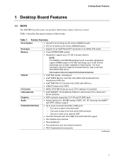
...memory, refer to the Intel World Wide Web site at: http://support.intel.com/support/motherboards/desktop/ • Intel® 845 chipset, consisting of: • Intel® 82845 Memory Controller Hub (MCH) with Accelerated Hub Architecture (AHA) bus • Intel® 82801BA I /O Control LAN (optional) Graphics Audio • microATX at 9.6 inches by 9.6 inches (D845HV... layout was used for an Intel® Pentium® 4 processor in an mPGA-478 socket • Three SDRAM DIMM sockets. • Designed to support up to 3.0 GB of system memory NOTE The D845HV and D845WN desktop boards have ...
...memory, refer to the Intel World Wide Web site at: http://support.intel.com/support/motherboards/desktop/ • Intel® 845 chipset, consisting of: • Intel® 82845 Memory Controller Hub (MCH) with Accelerated Hub Architecture (AHA) bus • Intel® 82801BA I /O Control LAN (optional) Graphics Audio • microATX at 9.6 inches by 9.6 inches (D845HV... layout was used for an Intel® Pentium® 4 processor in an mPGA-478 socket • Three SDRAM DIMM sockets. • Designed to support up to 3.0 GB of system memory NOTE The D845HV and D845WN desktop boards have ...
Product Guide
Page 8
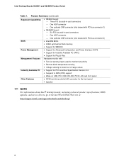
Intel Desktop Boards D845HV and D845WN Product Guide Table 1. Feature Summary (continued) Expansion Capabilities • D845HV board: Three PCI bus add-in card connectors One AGP connector One optional CNR connector (slot shared ...card connectors One AGP connector One optional CNR connector (slot shared with PCI bus connector 6) BIOS • Intel/AMI BIOS. • 4 Mbit symmetrical flash memory • Support for SMBIOS Power Management • Support for Advanced Configuration and Power Interface (ACPI) • Support for Instantly ...
Intel Desktop Boards D845HV and D845WN Product Guide Table 1. Feature Summary (continued) Expansion Capabilities • D845HV board: Three PCI bus add-in card connectors One AGP connector One optional CNR connector (slot shared ...card connectors One AGP connector One optional CNR connector (slot shared with PCI bus connector 6) BIOS • Intel/AMI BIOS. • 4 Mbit symmetrical flash memory • Support for SMBIOS Power Management • Support for Advanced Configuration and Power Interface (ACPI) • Support for Instantly ...
Product Guide
Page 9
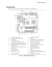
... major components on the D845HV board. D845HV Board Components 9 A BC D BB E F AA G Z H Y X I W J V K U T SQ N R PO ML OM11978 A CD-ROM connector (ATAPI) O Secondary IDE connector B Auxiliary line-in connector (ATAPI) P Speaker C AGP connector Q Intel 82801BA I/O Controller Hub ... core voltage connector S Chassis intrusion connector F Rear chassis fan connector (tachometer input) T Front chassis fan connector G Intel 82845 Memory Controller Hub (MCH) U Alternate power/sleep LED connector H Processor socket V Front panel connector I Processor fan connector ...
... major components on the D845HV board. D845HV Board Components 9 A BC D BB E F AA G Z H Y X I W J V K U T SQ N R PO ML OM11978 A CD-ROM connector (ATAPI) O Secondary IDE connector B Auxiliary line-in connector (ATAPI) P Speaker C AGP connector Q Intel 82801BA I/O Controller Hub ... core voltage connector S Chassis intrusion connector F Rear chassis fan connector (tachometer input) T Front chassis fan connector G Intel 82845 Memory Controller Hub (MCH) U Alternate power/sleep LED connector H Processor socket V Front panel connector I Processor fan connector ...

Product Guide
Page 10
... LED connector E 12 V processor core voltage connector S Chassis intrusion connector F Rear chassis fan connector (tachometer input) T Front chassis fan connector G Intel 82845 Memory Controller Hub (MCH) U Alternate power/sleep LED connector H Processor socket V Front panel connector I Processor fan connector (tachometer input) W Front panel ... (CNR) (optional) N Primary IDE connector BB Front panel audio connector Figure 2. D845WN Board Components 10 Intel Desktop Boards D845HV and D845WN Product Guide Figure 2 shows the location of the major components on the D845WN board.
... LED connector E 12 V processor core voltage connector S Chassis intrusion connector F Rear chassis fan connector (tachometer input) T Front chassis fan connector G Intel 82845 Memory Controller Hub (MCH) U Alternate power/sleep LED connector H Processor socket V Front panel connector I Processor fan connector (tachometer input) W Front panel ... (CNR) (optional) N Primary IDE connector BB Front panel audio connector Figure 2. D845WN Board Components 10 Intel Desktop Boards D845HV and D845WN Product Guide Figure 2 shows the location of the major components on the D845WN board.
Product Guide
Page 11
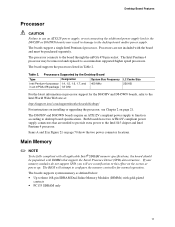
... E in damage to the desktop board and/or power supply. If your memory modules do not support SPD, you will attempt to configure the memory controller for the D845HV and D845WN boards, refer to the Intel World Wide Web site at power up. Table 2. Processors are needed to ...provide extra power to the Intel 845 chipset and Intel Pentium 4 processor. Processors Supported by the ...
... E in damage to the desktop board and/or power supply. If your memory modules do not support SPD, you will attempt to configure the memory controller for the D845HV and D845WN boards, refer to the Intel World Wide Web site at power up. Table 2. Processors are needed to ...provide extra power to the Intel 845 chipset and Intel Pentium 4 processor. Processors Supported by the ...

Product Guide
Page 12
... technologies for up to 3 GB, but this technology has not been validated on these memory requirements, refer to the D845HV or D845WN link on this Intel World Wide Web site: http://support.intel.com/support/motherboards/desktop/ For information about installing memory, see Chapter 2 starting on 512 Mbit technology up to 1.5 GB (with 256 Mbit...
... technologies for up to 3 GB, but this technology has not been validated on these memory requirements, refer to the D845HV or D845WN link on this Intel World Wide Web site: http://support.intel.com/support/motherboards/desktop/ For information about installing memory, see Chapter 2 starting on 512 Mbit technology up to 1.5 GB (with 256 Mbit...
Product Guide
Page 18
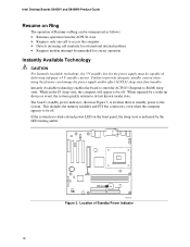
... on Ring can damage the power supply and/or effect ACPI S3 sleep state functionality. This includes the memory modules and PCI bus connectors, even when the computer appears to be off . Intel Desktop Boards D845HV and D845WN Product Guide Resume on Ring The operation of Resume on the front panel, the sleep...
... on Ring can damage the power supply and/or effect ACPI S3 sleep state functionality. This includes the memory modules and PCI bus connectors, even when the computer appears to be off . Intel Desktop Boards D845HV and D845WN Product Guide Resume on Ring The operation of Resume on the front panel, the sleep...

Product Guide
Page 19
...as outlined in and follow the steps outlined below: 1. Refer to the descriptions in Table 4. Add to the Intel Desktop Board D845HV/D845WN Technical Product Specification for the exact standby current requirements ** Dependent upon system configuration 19 Standby Current Requirements Instantly ... the standby current requirement. 4. Values are determined by specifications such as applicable. 6. Actual measurements may lose register settings stored in memory. Add, from the PCI 2.2 slots (nonwake-enabled) row, the total of the number of wake-enabled devices installed (PCI ...
...as outlined in and follow the steps outlined below: 1. Refer to the descriptions in Table 4. Add to the Intel Desktop Board D845HV/D845WN Technical Product Specification for the exact standby current requirements ** Dependent upon system configuration 19 Standby Current Requirements Instantly ... the standby current requirement. 4. Values are determined by specifications such as applicable. 6. Actual measurements may lose register settings stored in memory. Add, from the PCI 2.2 slots (nonwake-enabled) row, the total of the number of wake-enabled devices installed (PCI ...
Product Guide
Page 21
... chapter tells you how to: • Install the I/O shield • Install and remove the desktop board • Install and remove a processor • Install and remove memory • Install and remove an AGP retention mechanism and card • Connect the IDE cable • Set the BIOS jumper • Clear passwords • Replace...
... chapter tells you how to: • Install the I/O shield • Install and remove the desktop board • Install and remove a processor • Install and remove memory • Install and remove an AGP retention mechanism and card • Connect the IDE cable • Set the BIOS jumper • Clear passwords • Replace...
Product Guide
Page 29
... "Before You Begin" on page 21. 2. To install DIMMs, follow these documents through the Internet at : http://www.intel.com/technology/memory/pcsdram/spec/ The boards have three 168-pin DIMM sockets arranged as banks 0, 1, and 2 as shown in Figure 11. Remove the AGP video ...and closed). 29 Observe the precautions in the DIMM sockets prior to installing the AGP video card to the computer. Turn off all applicable Intel® SDRAM memory specifications, the boards require DIMMs that support the Serial Presence Detect (SPD) data structure. Remove the computer's cover and locate the DIMM ...
... "Before You Begin" on page 21. 2. To install DIMMs, follow these documents through the Internet at : http://www.intel.com/technology/memory/pcsdram/spec/ The boards have three 168-pin DIMM sockets arranged as banks 0, 1, and 2 as shown in Figure 11. Remove the AGP video ...and closed). 29 Observe the precautions in the DIMM sockets prior to installing the AGP video card to the computer. Turn off all applicable Intel® SDRAM memory specifications, the boards require DIMMs that support the Serial Presence Detect (SPD) data structure. Remove the computer's cover and locate the DIMM ...

Product Guide
Page 30
... the clips are pushed outward to installing the DIMMs. 11. Installing a Memory Module 5. When the DIMM is inserted, push down on the top edge of the DIMM with the keys in the socket (see inset in place. 10. Intel Desktop Boards D845HV and D845WN Product Guide 0 1 2 OM11986 Figure 11. Holding the DIMM by...
... the clips are pushed outward to installing the DIMMs. 11. Installing a Memory Module 5. When the DIMM is inserted, push down on the top edge of the DIMM with the keys in the socket (see inset in place. 10. Intel Desktop Boards D845HV and D845WN Product Guide 0 1 2 OM11986 Figure 11. Holding the DIMM by...

Product Guide
Page 31
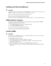
... of the socket. 7. Reinstall and reconnect any parts you removed it before installing the DIMMs). 9. Installing and Replacing Desktop Board Components Removing DIMMs To remove a memory module, follow these steps: 1. Observe the precautions in an anti-static package. 8. The DIMM pops out of the DIMM socket. Turn off the computer. 3. Remove...
... of the socket. 7. Reinstall and reconnect any parts you removed it before installing the DIMMs). 9. Installing and Replacing Desktop Board Components Removing DIMMs To remove a memory module, follow these steps: 1. Observe the precautions in an anti-static package. 8. The DIMM pops out of the DIMM socket. Turn off the computer. 3. Remove...
Product Guide
Page 39
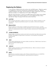
Installing and Replacing Desktop Board Components Replacing the Battery A coin-cell battery (CR2032) powers the real-time clock and CMOS memory. When the voltage drops below a certain level, the BIOS Setup program settings stored in CMOS RAM (for example, the date and time) might not be ...
Installing and Replacing Desktop Board Components Replacing the Battery A coin-cell battery (CR2032) powers the real-time clock and CMOS memory. When the voltage drops below a certain level, the BIOS Setup program settings stored in CMOS RAM (for example, the date and time) might not be ...

Product Guide
Page 43
...the file to a diskette. Close all other applications. This step is included in an automated update utility which combines the functionality of the Intel Flash Memory Update Utility and the ease-of use of Windows-based installation wizards. Your system will be rebooted at the last Express BIOS Update window. ... the executable file from the location on your hard drive. (You can update the system BIOS while in the dialog boxes to the D845HV or D845WN page and click the Express BIOS Update utility file for multiple identical systems.) 4. The BIOS file is required. Navigate to ...
...the file to a diskette. Close all other applications. This step is included in an automated update utility which combines the functionality of the Intel Flash Memory Update Utility and the ease-of use of Windows-based installation wizards. Your system will be rebooted at the last Express BIOS Update window. ... the executable file from the location on your hard drive. (You can update the system BIOS while in the dialog boxes to the D845HV or D845WN page and click the Express BIOS Update utility file for multiple identical systems.) 4. The BIOS file is required. Navigate to ...
Product Guide
Page 44
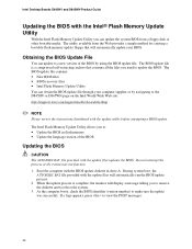
... run the BIOS update process. 2. The BIOS update file contains: • New BIOS files • BIOS recovery files • Intel Flash Memory Update Utility You can obtain the BIOS update file through your BIOS. As the computer boots, check the BIOS identifier (version number) ...update was successful. Intel Desktop Boards D845HV and D845WN Product Guide Updating the BIOS with the Intel® Flash Memory Update Utility With the Intel Flash Memory Update Utility you need to the D845HV or D845WN page on the Intel World Wide Web site: http://support.intel.com/support/motherboards/...
... run the BIOS update process. 2. The BIOS update file contains: • New BIOS files • BIOS recovery files • Intel Flash Memory Update Utility You can obtain the BIOS update file through your BIOS. As the computer boots, check the BIOS identifier (version number) ...update was successful. Intel Desktop Boards D845HV and D845WN Product Guide Updating the BIOS with the Intel® Flash Memory Update Utility With the Intel Flash Memory Update Utility you need to the D845HV or D845WN page on the Intel World Wide Web site: http://support.intel.com/support/motherboards/...
Product Guide
Page 47
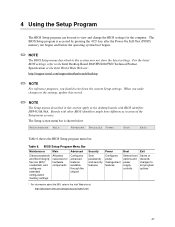
For the latest BIOS settings, refer to the Intel Desktop Board D845HV/D845WN Technical Product Specification or the Intel World Wide Web site: http://support.intel.com/support/motherboards/desktop ✏ NOTE For reference purposes, you make changes to the settings, update this record. ...Setup menu screens. BIOS Setup Program Menu Bar Maintenance Clears passwords and Boot Integrity Service (BIS)* credentials, and configures extended configuration memory settings Main Allocates resources for the computer. The BIOS Setup program is shown below. 4 Using the Setup Program The BIOS Setup...
For the latest BIOS settings, refer to the Intel Desktop Board D845HV/D845WN Technical Product Specification or the Intel World Wide Web site: http://support.intel.com/support/motherboards/desktop ✏ NOTE For reference purposes, you make changes to the settings, update this record. ...Setup menu screens. BIOS Setup Program Menu Bar Maintenance Clears passwords and Boot Integrity Service (BIS)* credentials, and configures extended configuration memory settings Main Allocates resources for the computer. The BIOS Setup program is shown below. 4 Using the Setup Program The BIOS Setup...


