
Technical Product Specification
Page 8
Intel NUC D53427RKE Technical Product Specification 2 Technical Reference 2.1 Memory Resources 41 2.1.1 Addressable Memory 41 2.2 Connectors and Headers 42 2.2.1 Back Panel Connectors 43 2.2.2 Connectors and Headers (Bottom 44 2.3 BIOS Setup Configuration Jumper 52 2.4 Intel® Management Engine BIOS Extension (Intel&#... Language Support 63 3.5.2 Custom Splash Screen 64 3.6 BIOS Recovery 64 3.7 Boot Options 65 3.7.1 Network Boot 65 3.7.2 Booting Without Attached Devices 65 3.7.3 Changing the Default Boot Device During POST 65 3.8 Hard Disk Drive Password Security Feature 66 3.9 ...
Intel NUC D53427RKE Technical Product Specification 2 Technical Reference 2.1 Memory Resources 41 2.1.1 Addressable Memory 41 2.2 Connectors and Headers 42 2.2.1 Back Panel Connectors 43 2.2.2 Connectors and Headers (Bottom 44 2.3 BIOS Setup Configuration Jumper 52 2.4 Intel® Management Engine BIOS Extension (Intel&#... Language Support 63 3.5.2 Custom Splash Screen 64 3.6 BIOS Recovery 64 3.7 Boot Options 65 3.7.1 Network Boot 65 3.7.2 Booting Without Attached Devices 65 3.7.3 Changing the Default Boot Device During POST 65 3.8 Hard Disk Drive Password Security Feature 66 3.9 ...

Technical Product Specification
Page 9
...Configuration Setup Jumper 52 13. Wake-up Devices and Events 33 10. Front Panel Header 49 15. Fan Header Current Capability 57 19. Boot Device Menu Options 65 24. Front-panel Power LED Blink Codes 69 ix LAN Connector LED Locations 28 6. Back Panel Connectors 43 9. ... Considerations for Front Panel USB 2.0 Dual-Port Header 51 12. Connection Diagram for a One-Color Power LED 50 16. Intel MEBX Reset Header Signals 54 18. Intel Visual BIOS Home Screen 61 Tables 1. Master Key and User Hard Drive Password Functions 66 25. Thermal Solution and Fan Header...
...Configuration Setup Jumper 52 13. Wake-up Devices and Events 33 10. Front Panel Header 49 15. Fan Header Current Capability 57 19. Boot Device Menu Options 65 24. Front-panel Power LED Blink Codes 69 ix LAN Connector LED Locations 28 6. Back Panel Connectors 43 9. ... Considerations for Front Panel USB 2.0 Dual-Port Header 51 12. Connection Diagram for a One-Color Power LED 50 16. Intel MEBX Reset Header Signals 54 18. Intel Visual BIOS Home Screen 61 Tables 1. Master Key and User Hard Drive Password Functions 66 25. Thermal Solution and Fan Header...
Technical Product Specification
Page 32
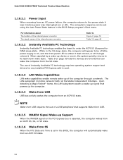
... Sleeping States Processor States Device States Targeted System Power (Note 1) G0 - sleeping state G1 - Context saved to disk. Suspend to the system. Cold boot is disconnected from applications and user settings to put the system as a whole into a low-power state. working S3 - D3 - Full power > ... the system chassis' power supply. 2. Suspend to the system. no power for wake-up logic. No power to RAM. Intel NUC D53427RKE Technical Product Specification 1.10.1.1 System States and Power States Under ACPI, the operating system directs all system and device power state ...
... Sleeping States Processor States Device States Targeted System Power (Note 1) G0 - sleeping state G1 - Context saved to disk. Suspend to the system. Cold boot is disconnected from applications and user settings to put the system as a whole into a low-power state. working S3 - D3 - Full power > ... the system chassis' power supply. 2. Suspend to the system. no power for wake-up logic. No power to RAM. Intel NUC D53427RKE Technical Product Specification 1.10.1.1 System States and Power States Under ACPI, the operating system directs all system and device power state ...
Technical Product Specification
Page 34
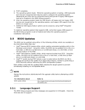
... computer from the S3 state. Table 9 on page 33 lists the devices and events that can be set in the BIOS Setup program's Boot menu. The LAN subsystem monitors network traffic at the Media Independent Interface. For information about The location of the internal power connector The signal... supply is off, and the front panel LED is amber if dual colored, or off ). The use of the computer through a network. Intel NUC D53427RKE Technical Product Specification 1.10.2.1 Power Input When resuming from an AC power failure, the computer returns to the power state it was in before ...
... computer from the S3 state. Table 9 on page 33 lists the devices and events that can be set in the BIOS Setup program's Boot menu. The LAN subsystem monitors network traffic at the Media Independent Interface. For information about The location of the internal power connector The signal... supply is off, and the front panel LED is amber if dual colored, or off ). The use of the computer through a network. Intel NUC D53427RKE Technical Product Specification 1.10.2.1 Power Input When resuming from an AC power failure, the computer returns to the power state it was in before ...

Technical Product Specification
Page 53
... MEBX Reset, a "CMOS battery failure" warning will accomplish the following: • Return all Intel ME parameters to reach end of POST before installing an MEBX reset jumper. The maintenance menu is... mode is required. 2.4 Intel® Management Engine BIOS Extension (Intel® MEBX) Reset Header The Intel® MEBX reset header (see Figure 13) allows you to reset the Intel ME configuration to clear the...restore the BIOS/CMOS settings to their default values. • Reset the Intel MEBX password to recover the BIOS configuration. After the POST runs, Setup runs automatically. Technical...
... MEBX Reset, a "CMOS battery failure" warning will accomplish the following: • Return all Intel ME parameters to reach end of POST before installing an MEBX reset jumper. The maintenance menu is... mode is required. 2.4 Intel® Management Engine BIOS Extension (Intel® MEBX) Reset Header The Intel® MEBX reset header (see Figure 13) allows you to reset the Intel ME configuration to clear the...restore the BIOS/CMOS settings to their default values. • Reset the Intel MEBX password to recover the BIOS configuration. After the POST runs, Setup runs automatically. Technical...

Technical Product Specification
Page 61
The BIOS Setup program is accessed by pressing the key after the Power-On Self-Test (POST) memory test begins and before the operating system boot begins. Figure 16. The SPI Flash contains the Visual BIOS Setup program, POST, the PCI auto-configuration utility, LAN EEPROM information, and Plug ...BIOSs are identified as RKPPT10H.86A. When the BIOS Setup configuration jumper is set to view and change the BIOS settings for the computer. Intel Visual BIOS Home Screen 61 The Visual BIOS Setup program can be used to configure mode and the computer is powered-up, the BIOS compares...
The BIOS Setup program is accessed by pressing the key after the Power-On Self-Test (POST) memory test begins and before the operating system boot begins. Figure 16. The SPI Flash contains the Visual BIOS Setup program, POST, the PCI auto-configuration utility, LAN EEPROM information, and Plug ...BIOSs are identified as RKPPT10H.86A. When the BIOS Setup configuration jumper is set to view and change the BIOS settings for the computer. Intel Visual BIOS Home Screen 61 The Visual BIOS Setup program can be used to configure mode and the computer is powered-up, the BIOS compares...
Technical Product Specification
Page 63
...; F7 switch during this utility, the BIOS can be updated from a file on the Intel World Wide Web site: • Intel® Express BIOS Update utility, which requires booting from the BIOS is set to Enabled and follow the operating system's installation instructions. 3.5 BIOS Updates ... USB support was set to Disabled in the BIOS Setup program.) 6. Overview of the following utilities, which are recognized by using Intel® Integrator Toolkit. The operating system loads. Similar to prevent accidentally installing an incompatible BIOS. Both utilities verify that Legacy USB ...
...; F7 switch during this utility, the BIOS can be updated from a file on the Intel World Wide Web site: • Intel® Express BIOS Update utility, which requires booting from the BIOS is set to Enabled and follow the operating system's installation instructions. 3.5 BIOS Updates ... USB support was set to Disabled in the BIOS Setup program.) 6. Overview of the following utilities, which are recognized by using Intel® Integrator Toolkit. The operating system loads. Similar to prevent accidentally installing an incompatible BIOS. Both utilities verify that Legacy USB ...
Technical Product Specification
Page 65
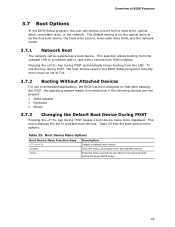
... menu must be set to Full. 3.7.2 Booting Without Attached Devices For use in card with a remote boot ROM installed. Table 23. Boot Device Menu Options Boot Device Menu Function Keys or Description Selects a default boot device Exits the menu, and boots from a hard drive, optical drive, removable...devices are not present: • Video adapter • Keyboard • Mouse 3.7.3 Changing the Default Boot Device During POST Pressing the key during POST automatically forces booting from the onboard LAN or a network add-in embedded applications, the BIOS has been designed so that...
... menu must be set to Full. 3.7.2 Booting Without Attached Devices For use in card with a remote boot ROM installed. Table 23. Boot Device Menu Options Boot Device Menu Function Keys or Description Selects a default boot device Exits the menu, and boots from a hard drive, optical drive, removable...devices are not present: • Video adapter • Keyboard • Mouse 3.7.3 Changing the Default Boot Device During POST Pressing the key during POST automatically forces booting from the onboard LAN or a network add-in embedded applications, the BIOS has been designed so that...
Technical Product Specification
Page 66
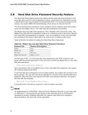
...the system will be locked upon each powercycle until the correct password is given. The passwords are prompted for during BIOS POST. Intel NUC D53427RKE Technical Product Specification 3.8 Hard Disk Drive Password Security Feature The Hard Disk Drive Password Security feature blocks read and write accesses to...A manual power cycle will automatically unlock drives on SATA port 0. Master Key and User Hard Drive Password Functions Password Set Password During Boot Neither Master only User only None None User only Master and User Set Master or User During every POST, if a User hard ...
...the system will be locked upon each powercycle until the correct password is given. The passwords are prompted for during BIOS POST. Intel NUC D53427RKE Technical Product Specification 3.8 Hard Disk Drive Password Security Feature The Hard Disk Drive Password Security feature blocks read and write accesses to...A manual power cycle will automatically unlock drives on SATA port 0. Master Key and User Hard Drive Password Functions Password Set Password During Boot Neither Master only User only None None User only Master and User Set Master or User During every POST, if a User hard ...
Technical Product Specification
Page 67
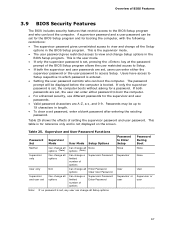
...of options Supervisor Password Enter Password Note: If no password is set, any user can change all Setup options. Table 25. Password to boot the computer. • For enhanced security, use different passwords for a password. Users have access to Setup respective to which password is ...all Enter Password options Clear User Password Supervisor and user set , the user can enter either password to Enter Setup None Password During Boot None Supervisor None User User Supervisor or Supervisor or user user 67 Passwords may be set , users can enter either the supervisor ...
...of options Supervisor Password Enter Password Note: If no password is set, any user can change all Setup options. Table 25. Password to boot the computer. • For enhanced security, use different passwords for a password. Users have access to Setup respective to which password is ...all Enter Password options Clear User Password Supervisor and user set , the user can enter either password to Enter Setup None Password During Boot None Supervisor None User User Supervisor or Supervisor or user user 67 Passwords may be set , users can enter either the supervisor ...
Technical Product Specification
Page 69
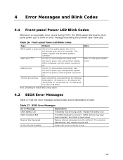
... CMOS Battery Low CMOS Checksum Bad The battery may have been corrupted. Memory Size Decreased Memory size has decreased since the last boot. No Boot Device Available System did not find a device to reset values. Table 27. The CMOS checksum is complete. Note: Disabled per...second each) two times, then 2.5-second pause (off), entire pattern repeats (blink and pause) until the BIOS update is incorrect. Run Setup to boot. 69 If no VGA option ROM is found. 4.2 BIOS Error Messages Table 27 lists the error messages and provides a brief description of 16 blinks...
... CMOS Battery Low CMOS Checksum Bad The battery may have been corrupted. Memory Size Decreased Memory size has decreased since the last boot. No Boot Device Available System did not find a device to reset values. Table 27. The CMOS checksum is complete. Note: Disabled per...second each) two times, then 2.5-second pause (off), entire pattern repeats (blink and pause) until the BIOS update is incorrect. Run Setup to boot. 69 If no VGA option ROM is found. 4.2 BIOS Error Messages Table 27 lists the error messages and provides a brief description of 16 blinks...


