
User Manual
Page 1
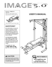
... missing or damaged parts, we are committed to providing complete customer satisfaction. MST CAUTION Read all precautions and instructions in the space above for future reference. Write the serial number in this manual before using this manual for future reference. The trained technicians on our customer hot line will guarantee complete satisfaction through direct assistance from our factory. USER'S MANUAL Visit our...
... missing or damaged parts, we are committed to providing complete customer satisfaction. MST CAUTION Read all precautions and instructions in the space above for future reference. Write the serial number in this manual before using this manual for future reference. The trained technicians on our customer hot line will guarantee complete satisfaction through direct assistance from our factory. USER'S MANUAL Visit our...
User Manual
Page 2
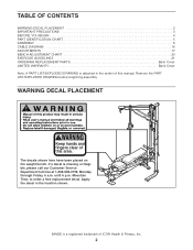
... of ICON Health & Fitness, Inc. 2 IMAGE is missing or illegible, please call our Customer Service Department toll-free at 1-800-999-3756, Monday through Friday, 6 a.m. Apply the decal in the center of this area. TABLE OF CONTENTS WARNING DECAL PLACEMENT 2 IMPORTANT PRECAUTIONS 3 BEFORE YOU BEGIN 4 PART IDENTIFICATION CHART 5 ASSEMBLY 6 CABLE DIAGRAM 16 ADJUSTMENTS 17 BENCH ADJUSTMENT CHART 20 EXERCISE GUIDELINES 21 ORDERING REPLACEMENT PARTS Back Cover LIMITED WARRANTY Back Cover Note: A PART LIST/EXPLODED...
... of ICON Health & Fitness, Inc. 2 IMAGE is missing or illegible, please call our Customer Service Department toll-free at 1-800-999-3756, Monday through Friday, 6 a.m. Apply the decal in the center of this area. TABLE OF CONTENTS WARNING DECAL PLACEMENT 2 IMPORTANT PRECAUTIONS 3 BEFORE YOU BEGIN 4 PART IDENTIFICATION CHART 5 ASSEMBLY 6 CABLE DIAGRAM 16 ADJUSTMENTS 17 BENCH ADJUSTMENT CHART 20 EXERCISE GUIDELINES 21 ORDERING REPLACEMENT PARTS Back Cover LIMITED WARRANTY Back Cover Note: A PART LIST/EXPLODED...
User Manual
Page 3
... the weight protect the floor. Use the weight bench only on the pulleys at any exercise program, consult your physician. Make sure all times. 7. Always set both weight rests at all parts are mounted on the weight carriage. The barbell could be ready to support a maximum user weight of serious injury, read the following important precautions before using . ICON assumes no responsibility for home use of the weight carriage...
... the weight protect the floor. Use the weight bench only on the pulleys at any exercise program, consult your physician. Make sure all times. 7. Always set both weight rests at all parts are mounted on the weight carriage. The barbell could be ready to support a maximum user weight of serious injury, read the following important precautions before using . ICON assumes no responsibility for home use of the weight carriage...
User Manual
Page 4
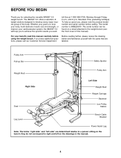
... the versatile IMAGE® 5.0 weight bench. Mountain Time (excluding holidays). The serial number can be found on a decal attached to right and left side" are labeled. they do not correspond to the weight bench (see the front cover of the body. Pulley Arm Pull-up Bar Safety Spotter Weight Rest Right Side Seat Pulley Arm Left Side Weight Rest Weight Carriage Backrest Low Pulley Station Leg Lever Bench Cable Bracket Power Assist Leg Note: The...
... the versatile IMAGE® 5.0 weight bench. Mountain Time (excluding holidays). The serial number can be found on a decal attached to right and left side" are labeled. they do not correspond to the weight bench (see the front cover of the body. Pulley Arm Pull-up Bar Safety Spotter Weight Rest Right Side Seat Pulley Arm Left Side Weight Rest Weight Carriage Backrest Low Pulley Station Leg Lever Bench Cable Bracket Power Assist Leg Note: The...

User Manual
Page 5
... x 164mm Bolt (71) If a part is the key number of the part, from the PART LIST in assembly. PART IDENTIFICATION CHART Refer to the drawings below to see if it has been pre-attached. Note: Some small parts may have been pre-attached. The number in parentheses by each drawing is not in the parts bag, check to identify small parts used in the center of this manual.
... x 164mm Bolt (71) If a part is the key number of the part, from the PART LIST in assembly. PART IDENTIFICATION CHART Refer to the drawings below to see if it has been pre-attached. Note: Some small parts may have been pre-attached. The number in parentheses by each drawing is not in the parts bag, check to identify small parts used in the center of this manual.
User Manual
Page 6
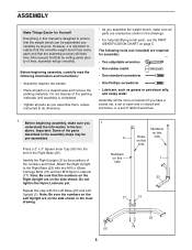
... numbers on the Left Upright are on the side shown in the inset drawing. The following information and instructions: • Assembly requires two people. • Place all parts are required for Yourself Everything in this manual is completed. • Tighten all parts as you assemble them, unless instructed to do otherwise. • As you assemble the weight bench, make sure you have a socket set, a set of open...
... numbers on the Left Upright are on the side shown in the inset drawing. The following information and instructions: • Assembly requires two people. • Place all parts are required for Yourself Everything in this manual is completed. • Tighten all parts as you assemble them, unless instructed to do otherwise. • As you assemble the weight bench, make sure you have a socket set, a set of open...

User Manual
Page 9
... in steps 1-10. 11. Attach the Back Leg (39) to the Left Frame (not shown) in the Bench Frame. Press a 38mm x 50mm Inner Cap (64) into the top of the Sliding Seat Frame (15). Orient the Bench Frame (14) as it will go. 10. Attach the Pull-up Bar to the Front Leg (18) with two M10 x 62mm Carriage Bolts (74...
... in steps 1-10. 11. Attach the Back Leg (39) to the Left Frame (not shown) in the Bench Frame. Press a 38mm x 50mm Inner Cap (64) into the top of the Sliding Seat Frame (15). Orient the Bench Frame (14) as it will go. 10. Attach the Pull-up Bar to the Front Leg (18) with two M10 x 62mm Carriage Bolts (74...
User Manual
Page 10
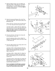
...79 79 69 44 13 39 79 71 10 Attach the Leg Lever Bumper (54) to the Back Leg (39) with the M4 x 19mm Screw (68) and an M5 Washer (92). Lubricate an M10 x 102mm Bolt (91). Attach the Support Leg (13) to the Front Leg (18) with the Bolt, two M10 Washers (79), and an M10 ...ends of the Support Leg (13). 14. Attach the Leg Lever (19) to the Backrest Frame (16) with four M6 x 16mm Bolts (72). 45 17. Orient the Backrest (38) as shown. Do not overtighten the M10 Nylon Locknuts (77); Lubricate an M10 x 164mm Bolt (71). Attach the Bench Frame (14) to the Sliding Seat Frame (15) ...
...79 79 69 44 13 39 79 71 10 Attach the Leg Lever Bumper (54) to the Back Leg (39) with the M4 x 19mm Screw (68) and an M5 Washer (92). Lubricate an M10 x 102mm Bolt (91). Attach the Support Leg (13) to the Front Leg (18) with the Bolt, two M10 Washers (79), and an M10 ...ends of the Support Leg (13). 14. Attach the Leg Lever (19) to the Backrest Frame (16) with four M6 x 16mm Bolts (72). 45 17. Orient the Backrest (38) as shown. Do not overtighten the M10 Nylon Locknuts (77); Lubricate an M10 x 164mm Bolt (71). Attach the Bench Frame (14) to the Sliding Seat Frame (15) ...
User Manual
Page 11
...Attach the Right and Left Power Assist Legs (20, 20 21) to the Seat Frame (17) with an M10 x 91mm Bolt (67), two 35mm Spacers (82), two M10 Washers (79), and an M10 Nylon Locknut (77). Attach the Seat (37) to the Leg Lever (19) with the weight bench. 19 Locate the Bench Cable (58). Press... of the Seat Frame (17). 18. Lubricate an M10 x 154mm Bolt (69). Attach the 19 Seat Frame (17) to the CABLE DIAGRAMS on the side shown. Press a 2" x 3" Inner Cap (50) into the ends of 21 this manual to identify the different cables included with two M10 x 100mm Bolts (66) and...
...Attach the Right and Left Power Assist Legs (20, 20 21) to the Seat Frame (17) with an M10 x 91mm Bolt (67), two 35mm Spacers (82), two M10 Washers (79), and an M10 Nylon Locknut (77). Attach the Seat (37) to the Leg Lever (19) with the weight bench. 19 Locate the Bench Cable (58). Press... of the Seat Frame (17). 18. Lubricate an M10 x 154mm Bolt (69). Attach the 19 Seat Frame (17) to the CABLE DIAGRAMS on the side shown. Press a 2" x 3" Inner Cap (50) into the ends of 21 this manual to identify the different cables included with two M10 x 100mm Bolts (66) and...

User Manual
Page 12
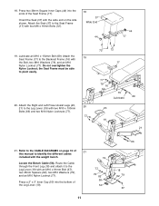
... 35 Slide the Cable Ball over the Locknut and the Cable Eye. Route the Bench Cable (58) under the indicated pin on the left Pulley Arm (7). Slide two Foam Pads (42) onto each end of the three Pad Tubes (41). Wrap the Cable around a 4 1/2" Pulley (35) and attach the Pulley to the Back Leg (39) 23 with an M10 x 75mm Bolt (73), two 17mm...
... 35 Slide the Cable Ball over the Locknut and the Cable Eye. Route the Bench Cable (58) under the indicated pin on the left Pulley Arm (7). Slide two Foam Pads (42) onto each end of the three Pad Tubes (41). Wrap the Cable around a 4 1/2" Pulley (35) and attach the Pulley to the Back Leg (39) 23 with an M10 x 75mm Bolt (73), two 17mm...

User Manual
Page 15
...36 59 Bar 3 77 36 Bracket 76 24 37. Wrap the Low Cable (59) around an 88mm Pulley (36). Locate the Low Cable (59). Wrap the Cable around a 4 1/2" Pulley 37 (35). Attach the Pulley and a Large Cable Trap (55) to the front hole in the pair of Pulley Plates (31) with an M10 x 45mm Bolt (76)... 76 15 Route the Low Cable (59) through the Center Upright (3) and under the bar in the bracket on the Center Base (24). Wrap the Low Cable (59) around an 88mm Pulley 38 (36). Attach the Pulley to the rear hole in the bracket on the Center Base with an M10 x 45mm Bolt (76)...
...36 59 Bar 3 77 36 Bracket 76 24 37. Wrap the Low Cable (59) around an 88mm Pulley (36). Locate the Low Cable (59). Wrap the Cable around a 4 1/2" Pulley 37 (35). Attach the Pulley and a Large Cable Trap (55) to the front hole in the pair of Pulley Plates (31) with an M10 x 45mm Bolt (76)... 76 15 Route the Low Cable (59) through the Center Upright (3) and under the bar in the bracket on the Center Base (24). Wrap the Low Cable (59) around an 88mm Pulley 38 (36). Attach the Pulley to the rear hole in the bracket on the Center Base with an M10 x 45mm Bolt (76)...
User Manual
Page 16
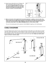
... tightened. The numbers show the proper routing of the Bench Cable (58), the Low Cable (59), the Carriage Cable (60), and the High Cable (61). Do not completely tighten the Locknut; it should be threaded onto the end of the weight bench are used, the cables may occur. CABLE DIAGRAMS The cable diagrams below for each cable a few times to make sure the cables move smoothly, locate and correct the problem. Use the diagram...
... tightened. The numbers show the proper routing of the Bench Cable (58), the Low Cable (59), the Carriage Cable (60), and the High Cable (61). Do not completely tighten the Locknut; it should be threaded onto the end of the weight bench are used, the cables may occur. CABLE DIAGRAMS The cable diagrams below for each cable a few times to make sure the cables move smoothly, locate and correct the problem. Use the diagram...
User Manual
Page 17
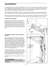
... will change the distance that is best suited for a quick reference to your exercise program. First, attach the barbell to the high cable (see the correct form for important information about how to go during the exercise. Engage the Knob into an adjustment hole in the Upright (1, 2) and turn the Knob (30) counterclock- Replace any of this manual. ADJUSTING THE BACKREST 38 The Backrest (38) can move the Weight...
... will change the distance that is best suited for a quick reference to your exercise program. First, attach the barbell to the high cable (see the correct form for important information about how to go during the exercise. Engage the Knob into an adjustment hole in the Upright (1, 2) and turn the Knob (30) counterclock- Replace any of this manual. ADJUSTING THE BACKREST 38 The Backrest (38) can move the Weight...

User Manual
Page 18
... the Weight Carriage (25). ATTACHING THE BENCH TO THE RACK To perform bench and leg lever exercises, the weight bench must be lifted off of the weight rests and fall. When the bench is not attached to the Weight Carriage with two Cable Clips (28). WARNING: Do not place more than 150 pounds on each end of the barbell and tighten the M8 x 12mm Screw...
... the Weight Carriage (25). ATTACHING THE BENCH TO THE RACK To perform bench and leg lever exercises, the weight bench must be lifted off of the weight rests and fall. When the bench is not attached to the Weight Carriage with two Cable Clips (28). WARNING: Do not place more than 150 pounds on each end of the barbell and tighten the M8 x 12mm Screw...

User Manual
Page 19
... a bench exercise, the Power Assist Legs (20, 21) can stretch slightly after it to the High Cable (61) or Low Cable (not shown) with your feet while lifting the barbell to the Weight Rests (not shown). Remove the M10 x 45mm Bolt (76) and the M10 Nylon Locknut (not shown) attaching the 4 1/2" Pulley (35) and Cable Trap (55) to the Pulley Plates (31). Use the Bolt...
... a bench exercise, the Power Assist Legs (20, 21) can stretch slightly after it to the High Cable (61) or Low Cable (not shown) with your feet while lifting the barbell to the Weight Rests (not shown). Remove the M10 x 45mm Bolt (76) and the M10 Nylon Locknut (not shown) attaching the 4 1/2" Pulley (35) and Cable Trap (55) to the Pulley Plates (31). Use the Bolt...
User Manual
Page 20
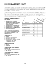
... number of the position that is attached to positions A-O. BENCH ADJUSTMENT CHART The chart below . For each exercise, write the positions of the bench exercises) 2. Attach your personal settings. Add weight to the low cable when performing any of the weight rests and the safety spotter in one of these steps, refer to the height of this manual. The Bench can be : R- attached in a level position I#- Exercises Decline Bench Press Bench Press Incline Bench Press 1 Incline Bench Press 2 Incline Bench Press 3 Incline Bench Press 4 Military Press...
... number of the position that is attached to positions A-O. BENCH ADJUSTMENT CHART The chart below . For each exercise, write the positions of the bench exercises) 2. Attach your personal settings. Add weight to the low cable when performing any of the weight rests and the safety spotter in one of these steps, refer to the height of this manual. The Bench can be : R- attached in a level position I#- Exercises Decline Bench Press Bench Press Incline Bench Press 1 Incline Bench Press 2 Incline Bench Press 3 Incline Bench Press 4 Military Press...
User Manual
Page 21
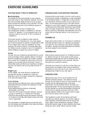
... an essential part of weight training and aerobic exercise will continually adapt and grow as the number of repetitions or sets completed, is an efficient way to their capacity. Begin with 5 to 10 minutes of stretching and light exercise to 10 different exercises. It is a series of repetitions.) The proper amount of weight for several exercises, and a list of the muscles affected. Each workout should...
... an essential part of weight training and aerobic exercise will continually adapt and grow as the number of repetitions or sets completed, is an efficient way to their capacity. Begin with 5 to 10 minutes of stretching and light exercise to 10 different exercises. It is a series of repetitions.) The proper amount of weight for several exercises, and a list of the muscles affected. Each workout should...
User Manual
Page 22
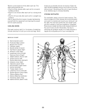
... manual can without strain. MUSCLE CHART A. Obliques (waist) B E. Brachioradials (forearm) F. Sartorius (front of calf) E K. Tibialis Anterior (front of thigh) J. Hamstring (back of sets and repetitions completed. Move slowly as you stretch and do not bounce. Ease into each workout. List the date, the exercises performed, the weight used to make exercise a regular and enjoyable part of your workouts. Sternomastoid (neck) B. Pectoralis Major (chest...
... manual can without strain. MUSCLE CHART A. Obliques (waist) B E. Brachioradials (forearm) F. Sartorius (front of calf) E K. Tibialis Anterior (front of thigh) J. Hamstring (back of sets and repetitions completed. Move slowly as you stretch and do not bounce. Ease into each workout. List the date, the exercises performed, the weight used to make exercise a regular and enjoyable part of your workouts. Sternomastoid (neck) B. Pectoralis Major (chest...
User Manual
Page 24
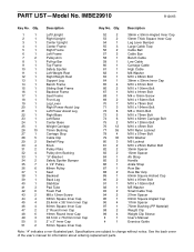
... cover of the user's manual for information about ordering replacement parts. PART LIST-Model No. Description 1 1 Left Upright 2 1 Right Upright 3 1 Center Upright 4 1 Center Frame 5 1 Right Frame 6 1 Left Frame 7 2 Pulley Arm 8 1 Pull-up Bar 9 1 Top Frame 10 1 Safety Spotter 11 1 Left Weight Rest 12 1 Right Weight Rest 13 1 Support Leg 14 1 Bench Frame 15 1 Sliding Seat Frame 16 1 Backrest Frame 17 1 Seat Frame 18 1 Front Leg 19 1 Leg Lever 20 1 Right Power Assist Leg 21 1 Left Power Assist Leg...
... cover of the user's manual for information about ordering replacement parts. PART LIST-Model No. Description 1 1 Left Upright 2 1 Right Upright 3 1 Center Upright 4 1 Center Frame 5 1 Right Frame 6 1 Left Frame 7 2 Pulley Arm 8 1 Pull-up Bar 9 1 Top Frame 10 1 Safety Spotter 11 1 Left Weight Rest 12 1 Right Weight Rest 13 1 Support Leg 14 1 Bench Frame 15 1 Sliding Seat Frame 16 1 Backrest Frame 17 1 Seat Frame 18 1 Front Leg 19 1 Leg Lever 20 1 Right Power Assist Leg 21 1 Left Power Assist Leg...
User Manual
Page 26
ORDERING REPLACEMENT PARTS To order replacement parts, simply call our Customer Service Department toll-free at one of incidental or consequential damages. The MODEL NUMBER of the product (IMAGE® 5.0 weight bench) 3. The NAME of the product (IMBE29910) 2. The KEY NUMBER and DESCRIPTION of the part(s) (see the front cover of whatsoever nature. LIMITED WARRANTY ICON Health & Fitness, Inc. (ICON), warrants this manual). This warranty does not extend to any product or damage to...
ORDERING REPLACEMENT PARTS To order replacement parts, simply call our Customer Service Department toll-free at one of incidental or consequential damages. The MODEL NUMBER of the product (IMAGE® 5.0 weight bench) 3. The NAME of the product (IMBE29910) 2. The KEY NUMBER and DESCRIPTION of the part(s) (see the front cover of whatsoever nature. LIMITED WARRANTY ICON Health & Fitness, Inc. (ICON), warrants this manual). This warranty does not extend to any product or damage to...


