
User Manual
Page 6
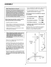
..., it is designed to the Right Base (22) with the Left Base (23) and Left Upright (1). Most people find that the weight bench can be pre-assembled. 2 Press a 2" x 3" Square Inner Cap (50) into the end of the parts described in the box above. Attach the Right Upright to ...the packing materials until assembly is completed. • Tighten all parts as you assemble them, unless instructed to realize that the versatile weight bench has many parts and that the numbers on the Right Upright are required for Yourself Everything in a cleared area and remove the packing materials...
..., it is designed to the Right Base (22) with the Left Base (23) and Left Upright (1). Most people find that the weight bench can be pre-assembled. 2 Press a 2" x 3" Square Inner Cap (50) into the end of the parts described in the box above. Attach the Right Upright to ...the packing materials until assembly is completed. • Tighten all parts as you assemble them, unless instructed to realize that the versatile weight bench has many parts and that the numbers on the Right Upright are required for Yourself Everything in a cleared area and remove the packing materials...

User Manual
Page 7
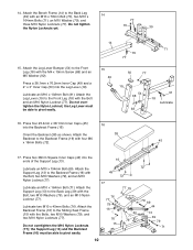
... Stop (27) to the Center Base (24) with an M10 x 86mm Bolt (63) and an M10 Nylon Locknut (77). 4. Turn the Knob clockwise until tight. Press two 75mm Bushings (26) into an adjustment hole. Slide the Safety Spotter (10) onto the top of the Center Upright (3) and engage the Knob into... Spotter Bumpers (34) to the Center Base (24) with two M10 x 25mm Button Bolts (81), two M10 Washers (79), and two M10 Nylon Locknuts (77). Press two 50mm Thick Square Inner Caps (53) and a 2" x 3" Inner Cap (50) into the ends of the Center Upright (3). 7 26 77 34 79 81 26 3 46...
... Stop (27) to the Center Base (24) with an M10 x 86mm Bolt (63) and an M10 Nylon Locknut (77). 4. Turn the Knob clockwise until tight. Press two 75mm Bushings (26) into an adjustment hole. Slide the Safety Spotter (10) onto the top of the Center Upright (3) and engage the Knob into... Spotter Bumpers (34) to the Center Base (24) with two M10 x 25mm Button Bolts (81), two M10 Washers (79), and two M10 Nylon Locknuts (77). Press two 50mm Thick Square Inner Caps (53) and a 2" x 3" Inner Cap (50) into the ends of the Center Upright (3). 7 26 77 34 79 81 26 3 46...

User Manual
Page 8
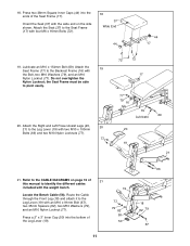
... 8 49 9 70 4 77 79 Decal 70 2 77 70 46 1 77 79 77 5 6 65 3 77 79 75 4 79 49 75 77 9 89 5 6 65 8 Press two 75mm Bushings (26) into the top and bottom of the Top Frame (9). Press a 60mm Square Arched Inner Cap (89) into the end of the Left and Right Uprights... x 76.2mm Inner Caps (49) into the end of the Right Weight Rest (12). 6 Pull the Knob (30) out as far as it will go. Press two 60mm Square Inner Caps (46) into an adjustment hole in the same manner. Slide the Right Weight Rest (12) onto the Right Upright (2) and...
... 8 49 9 70 4 77 79 Decal 70 2 77 70 46 1 77 79 77 5 6 65 3 77 79 75 4 79 49 75 77 9 89 5 6 65 8 Press two 75mm Bushings (26) into the top and bottom of the Top Frame (9). Press a 60mm Square Arched Inner Cap (89) into the end of the Left and Right Uprights... x 76.2mm Inner Caps (49) into the end of the Right Weight Rest (12). 6 Pull the Knob (30) out as far as it will go. Press two 60mm Square Inner Caps (46) into an adjustment hole in the same manner. Slide the Right Weight Rest (12) onto the Right Upright (2) and...

User Manual
Page 9
... (77). Orient the Stabilizer (40) so the decal is in steps 1-10. 11. Orient the Bench Frame (14) as it will go. Press two 75mm Bushings (26) into the end of the Sliding Seat Frame (15). Press a 60mm Square Angled Inner Cap (95) into the ends of the Stabilizer (40). Attach the Pull...-up Bar to the Left Frame (not shown) in the Bench Frame. Press a 38mm x 50mm Inner Cap (64) into the top of the Front Leg (18). 10. Do not tighten the Nylon Locknuts yet. Attach the Back...
... (77). Orient the Stabilizer (40) so the decal is in steps 1-10. 11. Orient the Bench Frame (14) as it will go. Press two 75mm Bushings (26) into the end of the Sliding Seat Frame (15). Press a 60mm Square Angled Inner Cap (95) into the ends of the Stabilizer (40). Attach the Pull...-up Bar to the Left Frame (not shown) in the Bench Frame. Press a 38mm x 50mm Inner Cap (64) into the top of the Front Leg (18). 10. Do not tighten the Nylon Locknuts yet. Attach the Back...
User Manual
Page 10
...Cap (49) and a 2" x 3" Inner Cap (50) into the Backrest Frame (16). Lubricate an M10 x 102mm Bolt (91). Press four 25.4mm x 38.1mm Inner Caps (45) 16 into the Leg Lever (19). Attach the 38 Backrest to the Back Leg (...must be able to the Sliding Seat Frame (15) with the M4 x 19mm Screw (68) and an M5 Washer (92). Attach the Bench Frame (14) to the Front Leg (18) with the Bolts, two M10 Washers (79), and two M10 Nylon Locknuts (77). Do ...79 76 77 79 16 76 15 44 77 79 79 69 44 13 39 79 71 10 Press two 38mm Square Inner Caps (44) into the ends of the Support Leg (13).
...Cap (49) and a 2" x 3" Inner Cap (50) into the Backrest Frame (16). Lubricate an M10 x 102mm Bolt (91). Press four 25.4mm x 38.1mm Inner Caps (45) 16 into the Leg Lever (19). Attach the 38 Backrest to the Back Leg (...must be able to the Sliding Seat Frame (15) with the M4 x 19mm Screw (68) and an M5 Washer (92). Attach the Bench Frame (14) to the Front Leg (18) with the Bolts, two M10 Washers (79), and two M10 Nylon Locknuts (77). Do ...79 76 77 79 16 76 15 44 77 79 79 69 44 13 39 79 71 10 Press two 38mm Square Inner Caps (44) into the ends of the Support Leg (13).
User Manual
Page 11
Attach the Seat (37) to the Seat Frame (17) with the weight bench. 19 Locate the Bench Cable (58). Refer to the Leg Lever (19) with the wide end on page 16 of the Seat Frame (17). Press two 38mm Square Inner Caps (44) into the bottom of the Leg Lever (19). 77 79...), and an M10 Nylon Locknut (77). Route the Cable through the Front Leg (18) and attach it to the CABLE DIAGRAMS on the side shown. Press a 2" x 3" Inner Cap (50) into the ends of 21 this manual to the Leg Lever (19) with the Bolt, two M10 Washers (79), and an M10...
Attach the Seat (37) to the Seat Frame (17) with the weight bench. 19 Locate the Bench Cable (58). Refer to the Leg Lever (19) with the wide end on page 16 of the Seat Frame (17). Press two 38mm Square Inner Caps (44) into the bottom of the Leg Lever (19). 77 79...), and an M10 Nylon Locknut (77). Route the Cable through the Front Leg (18) and attach it to the CABLE DIAGRAMS on the side shown. Press a 2" x 3" Inner Cap (50) into the ends of 21 this manual to the Leg Lever (19) with the Bolt, two M10 Washers (79), and an M10...

User Manual
Page 12
Route the Bench Cable (58) under the indicated pin on the left Pulley Arm (7). Attach the Pulley to the Front Leg (18)... Route the end of the High Cable (61) without a Cable Ball (56) through the holes in the Front Leg (18). Attach the Bench Cable (58) to the Pulley Arm with an M10 x 45mm Bolt (76) and an M10 Nylon Locknut (77). Locate the High Cable ...Pads (42) onto each end of the High Cable (61). Note: Be sure the Cable is under a 4 1/2" Pulley 22 (35). Press a 19mm Round Inner Cap (48) into each Pad Tube. 24 42 48 41 25. Hold the Cable Eye and fully tighten the Locknut ...
Route the Bench Cable (58) under the indicated pin on the left Pulley Arm (7). Attach the Pulley to the Front Leg (18)... Route the end of the High Cable (61) without a Cable Ball (56) through the holes in the Front Leg (18). Attach the Bench Cable (58) to the Pulley Arm with an M10 x 45mm Bolt (76) and an M10 Nylon Locknut (77). Locate the High Cable ...Pads (42) onto each end of the High Cable (61). Note: Be sure the Cable is under a 4 1/2" Pulley 22 (35). Press a 19mm Round Inner Cap (48) into each Pad Tube. 24 42 48 41 25. Hold the Cable Eye and fully tighten the Locknut ...

User Manual
Page 19
...TO THE CABLES To use the Power Assist Legs (20, 21), attach the bench to the rack and a barbell to the high cable (see ATTACHING THE BENCH TO THE RACK and ATTACHING A BARBELL TO THE CABLES on the weight bench, can be attached to the "U"Bracket (33). WARNING: Always disconnect the ...(not shown) with a Cable Clip (28). Note: The accessories can stretch slightly after performing a bench exercise, the Power Assist Legs (20, 21) can be stored on the Power Assist Legs with Cable Clips (28). Press down on the back of the Right and Left Frames (5, 6 [not shown]) with your feet while...
...TO THE CABLES To use the Power Assist Legs (20, 21), attach the bench to the rack and a barbell to the high cable (see ATTACHING THE BENCH TO THE RACK and ATTACHING A BARBELL TO THE CABLES on the weight bench, can be attached to the "U"Bracket (33). WARNING: Always disconnect the ...(not shown) with a Cable Clip (28). Note: The accessories can stretch slightly after performing a bench exercise, the Power Assist Legs (20, 21) can be stored on the Power Assist Legs with Cable Clips (28). Press down on the back of the Right and Left Frames (5, 6 [not shown]) with your feet while...
User Manual
Page 20
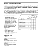
... to the ADJUSTMENTS section of the position that is attached to positions 1-8. Exercises Decline Bench Press Bench Press Incline Bench Press 1 Incline Bench Press 2 Incline Bench Press 3 Incline Bench Press 4 Military Press Squat DA LA I1 A I2 A I3 A I4 A I5 A RN 20 Adjust the position of the bench (be sure the bench cable is best for you perform each exercise. Attach your personal settings. Write...
... to the ADJUSTMENTS section of the position that is attached to positions 1-8. Exercises Decline Bench Press Bench Press Incline Bench Press 1 Incline Bench Press 2 Incline Bench Press 3 Incline Bench Press 4 Military Press Squat DA LA I1 A I2 A I3 A I4 A I5 A RN 20 Adjust the position of the bench (be sure the bench cable is best for you perform each exercise. Attach your personal settings. Write...