Hardware Maintenance Manual
Page 9
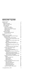
Netfinity 5500 - Type 8660 General Checkout 7 Diagnostic tools 10 Diagnostic programs 10 Power-on self-test (POST 11 POST beep codes 11 Error messages 12 POST error messages 12 Diagnostic error messages 12 Software-generated error messages . . . . . 12 System error log 12 Option diskettes 12 Diagnostic programs 13 Running Diagnostic programs 13 Viewing the test log 14 Features 15 Additional service information 17 Administration and Monitoring Utility Program . . 18 Before you begin 19 Installing the Server Utility Programs...
Netfinity 5500 - Type 8660 General Checkout 7 Diagnostic tools 10 Diagnostic programs 10 Power-on self-test (POST 11 POST beep codes 11 Error messages 12 POST error messages 12 Diagnostic error messages 12 Software-generated error messages . . . . . 12 System error log 12 Option diskettes 12 Diagnostic programs 13 Running Diagnostic programs 13 Viewing the test log 14 Features 15 Additional service information 17 Administration and Monitoring Utility Program . . 18 Before you begin 19 Installing the Server Utility Programs...

Hardware Maintenance Manual
Page 10
...Service with Netfinity Manager 66 Accessing the System Management Processor without Netfinity Manager 66 System Power menu selections . . . . . 68 Boot menu selections 69 Using remote video mode to monitor and access POST 71 Resolving configuration conflicts 73 Changing the software configuration setup . . 73 Changing the hardware configuration setup . 73 ServeRAID Configuration program 74 Software installation 74 Specifications 75 Starting the ServeRAID Configuration program . 77 During the initial startup of the server . . . . 77 After an operating system is installed . . . . 77 Using...
...Service with Netfinity Manager 66 Accessing the System Management Processor without Netfinity Manager 66 System Power menu selections . . . . . 68 Boot menu selections 69 Using remote video mode to monitor and access POST 71 Resolving configuration conflicts 73 Changing the software configuration setup . . 73 Changing the hardware configuration setup . 73 ServeRAID Configuration program 74 Software installation 74 Specifications 75 Starting the ServeRAID Configuration program . 77 During the initial startup of the server . . . . 77 After an operating system is installed . . . . 77 Using...

Hardware Maintenance Manual
Page 12
... Configuration/Setup Utility program . . . 145 Battery replacement 147 Before you begin 150 Changing jumper positions 151 Two-pin jumper blocks 151 Three-pin jumper blocks 153 Completing the installation 154 Installing the top cover 155 Installing the trim bezels and server door . . 156 Updating device records and reconfiguring the server 156 Controls and indicators 158 CD-ROM drive 161 Handling a CD 161 Loading a CD 161 DASD backplane removal 163 Diagnostics panel LEDs 164 External options 165 Connecting external SCSI devices . . . . . 165 Cabling...
... Configuration/Setup Utility program . . . 145 Battery replacement 147 Before you begin 150 Changing jumper positions 151 Two-pin jumper blocks 151 Three-pin jumper blocks 153 Completing the installation 154 Installing the top cover 155 Installing the trim bezels and server door . . 156 Updating device records and reconfiguring the server 156 Controls and indicators 158 CD-ROM drive 161 Handling a CD 161 Loading a CD 161 DASD backplane removal 163 Diagnostics panel LEDs 164 External options 165 Connecting external SCSI devices . . . . . 165 Cabling...

Hardware Maintenance Manual
Page 13
Type 8660 5 Installation procedure 165 Input/Output ports and connectors . . . . . 166 Serial ports 166 Management port C 167 Parallel port 167 Video port 168 Keyboard and auxiliary-device ports . . 169 Ethernet port 170 Universal serial bus ports 171 Front bezel removal 172 Hot-plug PCI adapter installation 173 Installing a non-hot-plug adapter 177 Verifying compatibility between network adapters and device drivers 180 Hot-swap power supply installation 181 Hot-swap power supply removal 185 Hot-swap fan assembly 187 Information LED panel 189 Information panel cover removal ...
Type 8660 5 Installation procedure 165 Input/Output ports and connectors . . . . . 166 Serial ports 166 Management port C 167 Parallel port 167 Video port 168 Keyboard and auxiliary-device ports . . 169 Ethernet port 170 Universal serial bus ports 171 Front bezel removal 172 Hot-plug PCI adapter installation 173 Installing a non-hot-plug adapter 177 Verifying compatibility between network adapters and device drivers 180 Hot-swap power supply installation 181 Hot-swap power supply removal 185 Hot-swap fan assembly 187 Information LED panel 189 Information panel cover removal ...

Hardware Maintenance Manual
Page 14
... unknown power-on password 258 System board removal 259 Top cover removal 262 Voltage regulator card removal 263 Symptom-to-FRU index 264 Beep symptoms 264 No beep symptoms 267 Control panel system error LED 267 Diagnostic error codes 270 Error symptoms 277 Power supply LED errors 278 POST error codes 280 SCSI error codes 285 ServeRAID II controller error codes/messages . 286 System board LEDs 290 System board SCSI LEDs 290 Undetermined problems 291 Parts listing (Type 8660 293 System 294 Hard disk drives and cables 302 Keyboards 303 Power cords 305 6 Netfinity Server...
... unknown power-on password 258 System board removal 259 Top cover removal 262 Voltage regulator card removal 263 Symptom-to-FRU index 264 Beep symptoms 264 No beep symptoms 267 Control panel system error LED 267 Diagnostic error codes 270 Error symptoms 277 Power supply LED errors 278 POST error codes 280 SCSI error codes 285 ServeRAID II controller error codes/messages . 286 System board LEDs 290 System board SCSI LEDs 290 Undetermined problems 291 Parts listing (Type 8660 293 System 294 Hard disk drives and cables 302 Keyboards 303 Power cords 305 6 Netfinity Server...

Hardware Maintenance Manual
Page 21
... server. You might have the system serviced. 3. The keyboard and mouse (pointing device) tests assume that a keyboard and mouse are attached to -FRU index" on page 264 and look for these ports. 5. Notes 1. Netfinity 5500 - If the problem persists, have to install a wrap connector on password and an administrator password is corrected, the other error messages usually will not occur the next time you run the test. If the diagnostic tests...
... server. You might have the system serviced. 3. The keyboard and mouse (pointing device) tests assume that a keyboard and mouse are attached to -FRU index" on page 264 and look for these ports. 5. Notes 1. Netfinity 5500 - If the problem persists, have to install a wrap connector on password and an administrator password is corrected, the other error messages usually will not occur the next time you run the test. If the diagnostic tests...
Hardware Maintenance Manual
Page 23
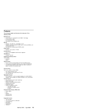
Dial back Predictive Failure Analysis (PFA) Alerts Power supplies Fans Memory Hard disk drives Microprocessors Integrated Functions Two serial ports Two universal serial bus (USB) ports One parallel port Mouse port Keyboard port Video port Netfinity 5500 - Read-only or read/write access - Four 32-bit hot-plug PCI slots Two standard (non-hot-plug) 32-bit PCI slots One 16-bit ISA slot Upgradable Firmware BIOS, diagnostics, system management processor, and ServeRAID II upgrades (when available) can be installed. Microprocessor Intel® Pentium® II microprocessor with MMX...
Dial back Predictive Failure Analysis (PFA) Alerts Power supplies Fans Memory Hard disk drives Microprocessors Integrated Functions Two serial ports Two universal serial bus (USB) ports One parallel port Mouse port Keyboard port Video port Netfinity 5500 - Read-only or read/write access - Four 32-bit hot-plug PCI slots Two standard (non-hot-plug) 32-bit PCI slots One 16-bit ISA slot Upgradable Firmware BIOS, diagnostics, system management processor, and ServeRAID II upgrades (when available) can be installed. Microprocessor Intel® Pentium® II microprocessor with MMX...
Hardware Maintenance Manual
Page 57
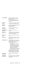
... controller. On - The current number of concurrent commands supported. The user chooses the recovery method when there is a ServeRAID controller startup error. The maximum numbers of defunct hard disk drives. Unattended Mode Code Block Version Boot Block Version Concurrent Commands Maximum Devices Supported Flash Program Count Defunct Disk Count Rebuild Rate Hot-Swap Rebuild Offline Logical Drive Count Configuration Update Count Off - The number of the defunct drive No rebuild, synchronization, or RAID level change operation is a startup error. Netfinity 5500...
... controller. On - The current number of concurrent commands supported. The user chooses the recovery method when there is a ServeRAID controller startup error. The maximum numbers of defunct hard disk drives. Unattended Mode Code Block Version Boot Block Version Concurrent Commands Maximum Devices Supported Flash Program Count Defunct Disk Count Rebuild Rate Hot-Swap Rebuild Offline Logical Drive Count Configuration Update Count Off - The number of the defunct drive No rebuild, synchronization, or RAID level change operation is a startup error. Netfinity 5500...
Hardware Maintenance Manual
Page 63
... small number of cases, minor tuning might have to set any jumpers or configure the controller for the different operating speeds, Fast Ethernet and standard Ethernet are currently hosted on the system board. that the cabling in the network be designed and implemented. This mixed network consists of standard Ethernet connections at the workstations and Fast Ethernet connections at the servers. If you need additional Ethernet connections, you must install a device driver to enable the operating system...
... small number of cases, minor tuning might have to set any jumpers or configure the controller for the different operating speeds, Fast Ethernet and standard Ethernet are currently hosted on the system board. that the cabling in the network be designed and implemented. This mixed network consists of standard Ethernet connections at the workstations and Fast Ethernet connections at the servers. If you need additional Ethernet connections, you must install a device driver to enable the operating system...

Hardware Maintenance Manual
Page 66
... switches on page 257. 3. Set jumpers or switches on the number and types of hardware devices and software programs that are typically, but not always, required to the ServeRAID controller on page 81 for installation and configuration. and change interrupt request (IRQ) settings; See the device installation instructions. 58 Netfinity Server HMM change the startup sequence for starting up the server and accessing the Configuration/Setup Utility program. Reading the instructions helps you to define and maintain the disk...
... switches on page 257. 3. Set jumpers or switches on the number and types of hardware devices and software programs that are typically, but not always, required to the ServeRAID controller on page 81 for installation and configuration. and change interrupt request (IRQ) settings; See the device installation instructions. 58 Netfinity Server HMM change the startup sequence for starting up the server and accessing the Configuration/Setup Utility program. Reading the instructions helps you to define and maintain the disk...

Hardware Maintenance Manual
Page 70
... Ethernet controller is an optional redundant network interface card (NIC adapter) that you want to upgrade the primary adapter hardware. In failover mode, if the primary Ethernet controller detects a link failure, all Ethernet traffic associated with the adapter and in the server. This can configure the server to install the AMD PCNet Ethernet Family adapter device driver. 62 Netfinity Server HMM You can configure either the integrated Ethernet controller or the NIC adapter as the primary Ethernet controller, you can be used...
... Ethernet controller is an optional redundant network interface card (NIC adapter) that you want to upgrade the primary adapter hardware. In failover mode, if the primary Ethernet controller detects a link failure, all Ethernet traffic associated with the adapter and in the server. This can configure the server to install the AMD PCNet Ethernet Family adapter device driver. 62 Netfinity Server HMM You can configure either the integrated Ethernet controller or the NIC adapter as the primary Ethernet controller, you can be used...

Hardware Maintenance Manual
Page 74
... password. Remote video mode enables you to the system management processor. The modem settings you will be accessed during POST. System requirements for the Advanced System Management Service with Netfinity Manager: The minimum system requirements for using the Advanced System Management service are: System management processor (built into the Netfinity 5500) Netfinity Manager or Client Services for Netfinity Manager, version 5.10.4 or later 2 MB of monitor, configuration, and error log data. While you are monitoring POST on the system management processor. Use...
... password. Remote video mode enables you to the system management processor. The modem settings you will be accessed during POST. System requirements for the Advanced System Management Service with Netfinity Manager: The minimum system requirements for using the Advanced System Management service are: System management processor (built into the Netfinity 5500) Netfinity Manager or Client Services for Netfinity Manager, version 5.10.4 or later 2 MB of monitor, configuration, and error log data. While you are monitoring POST on the system management processor. Use...

Hardware Maintenance Manual
Page 121
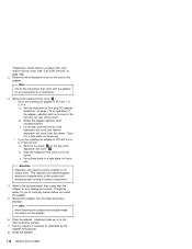
... disk-array configuration" on page 77). 2. then, press Enter. Change Adapter Host/SCSI ID 4. Enable Hot Swap Rebuild 2. To see "Starting the ServeRAID Configuration program" on page 126 for more information.) Viewing the disk-array configuration: To view the current configuration: 1. Back up the logical drives): a. enable or disable; Press Esc to return to the View Configuration screen. Netfinity 5500 - Press any key to return to the Advanced Functions menu. 7. Set BIOS...
... disk-array configuration" on page 77). 2. then, press Enter. Change Adapter Host/SCSI ID 4. Enable Hot Swap Rebuild 2. To see "Starting the ServeRAID Configuration program" on page 126 for more information.) Viewing the disk-array configuration: To view the current configuration: 1. Back up the logical drives): a. enable or disable; Press Esc to return to the View Configuration screen. Netfinity 5500 - Press any key to return to the Advanced Functions menu. 7. Set BIOS...
Hardware Maintenance Manual
Page 124
... on page 77). 116 Netfinity Server HMM Change Adapter Host/SCSI ID lets you specify which uses the settings to identify drives, to control power to specific drives, and to 20 MHz, the SCSI bus for the ServeRAID controller. If you are blocked or have a bad stripe. (See "Changing the RAID parameters" on page 126 for Unattended Mode, CD-ROM Boot, and Read Ahead. Set Channel → Bank...
... on page 77). 116 Netfinity Server HMM Change Adapter Host/SCSI ID lets you specify which uses the settings to identify drives, to control power to specific drives, and to 20 MHz, the SCSI bus for the ServeRAID controller. If you are blocked or have a bad stripe. (See "Changing the RAID parameters" on page 126 for Unattended Mode, CD-ROM Boot, and Read Ahead. Set Channel → Bank...
Hardware Maintenance Manual
Page 186
... the adapter for operation of the adapter retention latch on page 262). 2. Note Check the instructions that comes with the adapter for you will use . Rotate the adapter retention latch counterclockwise. b. c. Remove the screw 1 on page 220); See the illustration in "Hot-plug PCI adapter installation" on page 173 for any jumpers or switches as described by the adapter manufacturer. 8. Remove the adapter from the server. Set any cabling instructions. This...
... the adapter for operation of the adapter retention latch on page 262). 2. Note Check the instructions that comes with the adapter for you will use . Rotate the adapter retention latch counterclockwise. b. c. Remove the screw 1 on page 220); See the illustration in "Hot-plug PCI adapter installation" on page 173 for any jumpers or switches as described by the adapter manufacturer. 8. Remove the adapter from the server. Set any cabling instructions. This...

Hardware Maintenance Manual
Page 202
... connects here. External Connector Knockouts PCI Expansion Slots Mouse Connector Ethernet Connector Keyboard Connector Power Supply 1 Universal Serial Bus 1 Universal Serial Bus 2 ISA Expansion Slot Parallel Connector Serial A Connector Attention Lights for modems and other serial devices connect here to these two universal serial bus (USB) connectors. See "Devices and I /O devices to the two 9-pin serial connectors, ports A and B. You can attach I /O ports" on the rear of the Netfinity 5500 comes with the system management processor. Input/Output connectors and expansion slots...
... connects here. External Connector Knockouts PCI Expansion Slots Mouse Connector Ethernet Connector Keyboard Connector Power Supply 1 Universal Serial Bus 1 Universal Serial Bus 2 ISA Expansion Slot Parallel Connector Serial A Connector Attention Lights for modems and other serial devices connect here to these two universal serial bus (USB) connectors. See "Devices and I /O devices to the two 9-pin serial connectors, ports A and B. You can attach I /O ports" on the rear of the Netfinity 5500 comes with the system management processor. Input/Output connectors and expansion slots...

Hardware Maintenance Manual
Page 265
... pins 2 and 3 to disable the RAID controller. The default position is a jumper installed on pins 1 and 2. You do not need to move the jumper back to be turned on . Changing the position of this jumper bypasses the power-on password check if the jumper has been moved since the server was last powered on without a control panel or system management processor. In normal operation, there is set. Move the the jumper to pins 2 and 3 to disable the Ethernet controller. Changing...
... pins 2 and 3 to disable the RAID controller. The default position is a jumper installed on pins 1 and 2. You do not need to move the jumper back to be turned on . Changing the position of this jumper bypasses the power-on password check if the jumper has been moved since the server was last powered on without a control panel or system management processor. In normal operation, there is set. Move the the jumper to pins 2 and 3 to disable the Ethernet controller. Changing...

Hardware Maintenance Manual
Page 285
... device driver. The diskette contains the necessary files to bypass the diskette drive, replace the diskette drive. 1. Display Adapter/System Board Netfinity 5500 - CD-ROM drive tray is not working properly. If you have their own self-tests. Clean the optical-head lens. 3. CD-ROM Drive 1. Run Configuration/Setup, enabled primary IDE channel. 2. Clean the CD 2. If there is a diskette in the configuration programs. 2. FRU/Action 1. Check cables and jumpers. 3. Check for adjusting and testing instructions...
... device driver. The diskette contains the necessary files to bypass the diskette drive, replace the diskette drive. 1. Display Adapter/System Board Netfinity 5500 - CD-ROM drive tray is not working properly. If you have their own self-tests. Clean the optical-head lens. 3. CD-ROM Drive 1. Run Configuration/Setup, enabled primary IDE channel. 2. Clean the CD 2. If there is a diskette in the configuration programs. 2. FRU/Action 1. Check cables and jumpers. 3. Check for adjusting and testing instructions...

Hardware Maintenance Manual
Page 290
...Setup 3. System Board 1. Battery/CMOS Chip 3. Fixed Disk Adapter 4. System Board 282 Netfinity Server HMM Run Configuration/Setup 2. Keyboard 2. Drive Cable 4. Run Configuration/Setup 2. Disconnect external cable on page 98) 301 (Keyboard or keyboard controller error) 303 (Keyboard controller error) 602 (Invalid diskette boot record) 604 (Diskette drive error) 605 (Unlock failure) 662 (Diskette drive configuration error) 762 (Coprocessor configuration error) 962 (Parallel port error) 11XX (System board serial port 1 or 2 error) 1762 (Fixed Disk Configuration error...
...Setup 3. System Board 1. Battery/CMOS Chip 3. Fixed Disk Adapter 4. System Board 282 Netfinity Server HMM Run Configuration/Setup 2. Keyboard 2. Drive Cable 4. Run Configuration/Setup 2. Disconnect external cable on page 98) 301 (Keyboard or keyboard controller error) 303 (Keyboard controller error) 602 (Invalid diskette boot record) 604 (Diskette drive error) 605 (Unlock failure) 662 (Diskette drive configuration error) 762 (Coprocessor configuration error) 962 (Parallel port error) 11XX (System board serial port 1 or 2 error) 1762 (Fixed Disk Configuration error...
Hardware Maintenance Manual
Page 392
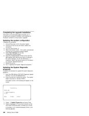
... the IBM Netfinity 5500 M20 Diagnostic Update Diskette 1 of 2 into the CD-ROM drive. Connect the power cord to "Updating the System Diagnostic programs." Connect all other server and device cables and connectors. 3. If necessary, refer to restart the server. Restart the server. 8. Insert the HardwareGuide CD that comes with the IBM Netfinity 5500 M20 Server Library contained in this procedure. 1. Press Ctrl+Alt+Del to the Server Library for this processor upgrade. Flash Utility Select one: 1. Update Diagnostics...
... the IBM Netfinity 5500 M20 Diagnostic Update Diskette 1 of 2 into the CD-ROM drive. Connect the power cord to "Updating the System Diagnostic programs." Connect all other server and device cables and connectors. 3. If necessary, refer to restart the server. Restart the server. 8. Insert the HardwareGuide CD that comes with the IBM Netfinity 5500 M20 Server Library contained in this procedure. 1. Press Ctrl+Alt+Del to the Server Library for this processor upgrade. Flash Utility Select one: 1. Update Diagnostics...


