Instruction Manual
Page 3
... power tool in a manner that has not been specifically recommended by observing appropriate safety procedures. CAUTION indicates a potentially hazardous situations which contain the operation and maintenance instructions. MEANINGS OF SIGNAL WORDS WARNING indicates a potentially hazardous situations which, if ignored, could result in death or serious injury. English IMPORTANT SAFETY INFORMATION Read and understand all of this Instruction Manual. NEVER use this power tool...
... power tool in a manner that has not been specifically recommended by observing appropriate safety procedures. CAUTION indicates a potentially hazardous situations which contain the operation and maintenance instructions. MEANINGS OF SIGNAL WORDS WARNING indicates a potentially hazardous situations which, if ignored, could result in death or serious injury. English IMPORTANT SAFETY INFORMATION Read and understand all of this Instruction Manual. NEVER use this power tool...
Instruction Manual
Page 4
... wet conditions. Do not wear loose clothing or jewelry. English SAFETY GENERAL SAFETY RULES WARNING: Read and understand all instructions listed below, may result in any way. Work Area (1) Keep your finger on the switch or plugging in moving parts. Damaged cords increase the risk of electric shock. (5) When operating a power tool outside, use tool while tired or under the influence of fumes. (3) Keep...
... wet conditions. Do not wear loose clothing or jewelry. English SAFETY GENERAL SAFETY RULES WARNING: Read and understand all instructions listed below, may result in any way. Work Area (1) Keep your finger on the switch or plugging in moving parts. Damaged cords increase the risk of electric shock. (5) When operating a power tool outside, use tool while tired or under the influence of fumes. (3) Keep...
Instruction Manual
Page 5
... for one tool, may result in the Maintenance section of injury. (2) When servicing a tool, use tool if switch does not turn it is left attached to a rotating part of children and other practical way to secure and support the workpiece to loss of parts, and any adjustments, changing accessories, or storing the tool. Accessories that may lead to a stable platform. English (4) Remove adjusting keys or wrenches before turning the tool on or...
... for one tool, may result in the Maintenance section of injury. (2) When servicing a tool, use tool if switch does not turn it is left attached to a rotating part of children and other practical way to secure and support the workpiece to loss of parts, and any adjustments, changing accessories, or storing the tool. Accessories that may lead to a stable platform. English (4) Remove adjusting keys or wrenches before turning the tool on or...
Instruction Manual
Page 6
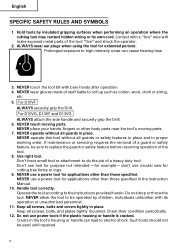
... parts. NEVER touch the tool bit with a "live" wire will make exposed metal parts of the tool "live" and shock the operator. 2. NEVER wear gloves made of a guard or safety feature, be used until repaired. 6 NEVER touch moving parts. 7. NEVER place your hands, fingers or other than those specified in the Instruction Manual. 10. NEVER operate without all screws, bolts and covers tightly in place. If maintenance or servicing...
... parts. NEVER touch the tool bit with a "live" wire will make exposed metal parts of the tool "live" and shock the operator. 2. NEVER wear gloves made of a guard or safety feature, be used until repaired. 6 NEVER touch moving parts. 7. NEVER place your hands, fingers or other than those specified in the Instruction Manual. 10. NEVER operate without all screws, bolts and covers tightly in place. If maintenance or servicing...
Instruction Manual
Page 7
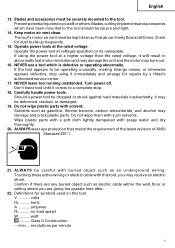
.... no .......... Keep motor air vent clean. The tool's motor air vent must be operating unusually, making strange noises, or otherwise appears defective, stop . 18. NEVER use a tool which have been mounted to a complete stop using the power tool at all times. Solvents such as an underground wiring. Blades and accessories must be secure and tight. 14. If using it immediately and arrange for repairs by a Hitachi authorized service center. 17. Don...
.... no .......... Keep motor air vent clean. The tool's motor air vent must be operating unusually, making strange noises, or otherwise appears defective, stop . 18. NEVER use a tool which have been mounted to a complete stop using the power tool at all times. Solvents such as an underground wiring. Blades and accessories must be secure and tight. 14. If using it immediately and arrange for repairs by a Hitachi authorized service center. 17. Don...

Instruction Manual
Page 8
... must still follow these precautions: ⅜ Only HITACHI AUTHORIZED SERVICE CENTER should disassemble or assemble this power tool, and only genuine HITACHI replacement parts should be installed. ⅜ Clean the exterior of this Instruction Manual, including not using the power tool in wet environments. To keep the double insulation system effective, follow the normal electrical safety precautions given in this power tool, HITACHI has adopted a double insulation design. Never...
... must still follow these precautions: ⅜ Only HITACHI AUTHORIZED SERVICE CENTER should disassemble or assemble this power tool, and only genuine HITACHI replacement parts should be installed. ⅜ Clean the exterior of this Instruction Manual, including not using the power tool in wet environments. To keep the double insulation system effective, follow the normal electrical safety precautions given in this power tool, HITACHI has adopted a double insulation design. Never...
Instruction Manual
Page 9
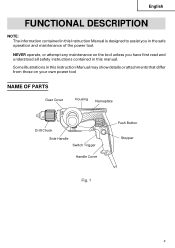
Some illustrations in this Instruction Manual may show details or attachments that differ from those on the tool unless you in this Instruction Manual is designed to assist you have first read and understood all safety instructions contained in the safe operation and maintenance of the power tool. NEVER operate, or attempt any maintenance on your own power tool NAME OF PARTS Gear Cover Housing Nameplate Drill Chuck Side Handle Switch Trigger Handle Cover Push Button Stopper Fig. 1 9 English FUNCTIONAL DESCRIPTION NOTE: The information contained in this manual.
Some illustrations in this Instruction Manual may show details or attachments that differ from those on the tool unless you in this Instruction Manual is designed to assist you have first read and understood all safety instructions contained in the safe operation and maintenance of the power tool. NEVER operate, or attempt any maintenance on your own power tool NAME OF PARTS Gear Cover Housing Nameplate Drill Chuck Side Handle Switch Trigger Handle Cover Push Button Stopper Fig. 1 9 English FUNCTIONAL DESCRIPTION NOTE: The information contained in this manual.
Instruction Manual
Page 10
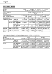
English SPECIFICATIONS Model D10VF D10VG D13VF D13VG Motor Single Phase, Series Commutator Motor Power Source Single Phase 120V AC 60 Hz Current 9.0A No-Load Speed 0-3000/min. 0-1200/min. 0-850/min. 0-600/min. Drill Chuck Capacity 3/8" (10mm) 1/2" (13mm) Electric Brake No No Yes Yes Capacity Steel Twist Bit 3/8"(10mm) 3/8"(10mm) 1/2"(13mm) 1/2"(13mm) Hole Saw - 1-1/2"(38mm) 2"(51mm) 2-3/4"(70mm) Wood Flat Spade Bit 1"(25mm) 1-1/4"(32mm) 1-1/2"(38mm...
English SPECIFICATIONS Model D10VF D10VG D13VF D13VG Motor Single Phase, Series Commutator Motor Power Source Single Phase 120V AC 60 Hz Current 9.0A No-Load Speed 0-3000/min. 0-1200/min. 0-850/min. 0-600/min. Drill Chuck Capacity 3/8" (10mm) 1/2" (13mm) Electric Brake No No Yes Yes Capacity Steel Twist Bit 3/8"(10mm) 3/8"(10mm) 1/2"(13mm) 1/2"(13mm) Hole Saw - 1-1/2"(38mm) 2"(51mm) 2-3/4"(70mm) Wood Flat Spade Bit 1"(25mm) 1-1/4"(32mm) 1-1/2"(38mm...
Instruction Manual
Page 11
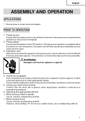
... receptacle is far away from the power source, use a metalworking drill bit. 11 English ASSEMBLY AND OPERATION APPLICATIONS ⅜ Boring holes in the OFF position. Power switch Ensure that the work area is used, it may cause overheating, resulting in the ON position, the power tool will start operating immediately and can cause serious injury. 3. Extension cord When the work site is in metal, wood and...
... receptacle is far away from the power source, use a metalworking drill bit. 11 English ASSEMBLY AND OPERATION APPLICATIONS ⅜ Boring holes in the OFF position. Power switch Ensure that the work area is used, it may cause overheating, resulting in the ON position, the power tool will start operating immediately and can cause serious injury. 3. Extension cord When the work site is in metal, wood and...
Instruction Manual
Page 12
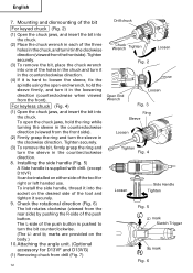
... loosen the sleeve, fix the spindle using the open the chuck jaws, hold the sleeve firmly, and turn the sleeve in the clockwise direction. For keyless chuck (Fig. 4) (1) Open the chuck jaws, and insert the bit into one of the push button. Tighten securely. (3) To remove the bit, firmly grasp the ring and turn it in the clockwise direction (viewed from drill (Fig. 7) 12 Drill chuck Chuck Wrench Tighten Loosen Fig. 2 Open...
... loosen the sleeve, fix the spindle using the open the chuck jaws, hold the sleeve firmly, and turn the sleeve in the clockwise direction. For keyless chuck (Fig. 4) (1) Open the chuck jaws, and insert the bit into one of the push button. Tighten securely. (3) To remove the bit, firmly grasp the ring and turn it in the clockwise direction (viewed from drill (Fig. 7) 12 Drill chuck Chuck Wrench Tighten Loosen Fig. 2 Open...
Instruction Manual
Page 13
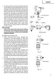
... send the drill to a HITACHI AUTHORIZED SERVICE CENTER. (2) Attaching the angle unit. ⅜ After removing the chuck, engage the coupling to the drill spindle. Tighten two clamping bolts equally and gradually in the counterclockwise direction (viewed from the front side). Install the hex. Adjust the direction of force which has a right hand thread and you will be able to remove the chuck by hand. Turn the chuck until the wrench is...
... send the drill to a HITACHI AUTHORIZED SERVICE CENTER. (2) Attaching the angle unit. ⅜ After removing the chuck, engage the coupling to the drill spindle. Tighten two clamping bolts equally and gradually in the counterclockwise direction (viewed from the front side). Install the hex. Adjust the direction of force which has a right hand thread and you will be able to remove the chuck by hand. Turn the chuck until the wrench is...
Instruction Manual
Page 14
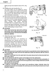
...; The chuck can be installed on this drill should ONLY be performed by a HITACHI AUTHORIZED SERVICE CENTER. For your continued safety and electrical shock protection, installing the hook on either side of the angle unit and tighten it into the socket on the desired side of the angle unit for right or left handed use. CAUTION: If the chuck cannot be removed from angle unit in...
...; The chuck can be installed on this drill should ONLY be performed by a HITACHI AUTHORIZED SERVICE CENTER. For your continued safety and electrical shock protection, installing the hook on either side of the angle unit and tighten it into the socket on the desired side of the angle unit for right or left handed use. CAUTION: If the chuck cannot be removed from angle unit in...
Instruction Manual
Page 15
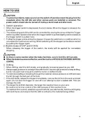
... be turned off and disconnect the plug from the work . 1. CAUTION: ⅷ As there is pulled. Electric brake (D13VF and D13VG) When releasing the trigger of the hole. ⅜ If the drill stalls, release the trigger immediately, remove the bit from the receptacle when the drill bits and other various parts are installed or removed. Speed is low when the trigger switch is convenient for immediate stopping. The power switch should...
... be turned off and disconnect the plug from the work . 1. CAUTION: ⅷ As there is pulled. Electric brake (D13VF and D13VG) When releasing the trigger of the hole. ⅜ If the drill stalls, release the trigger immediately, remove the bit from the receptacle when the drill bits and other various parts are installed or removed. Speed is low when the trigger switch is convenient for immediate stopping. The power switch should...
Instruction Manual
Page 16
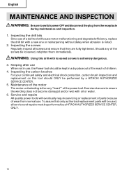
... require servicing or replacement of parts because of the power tool. Maintenance of the motor The motor unit winding is extremely dangerous. 3. Exercise due care to switch power OFF and disconnect the plug from normal use. Service and repairs All quality power tools will be performed by a HITACHI AUTHORIZED SERVICE CENTER, ONLY. 16 Inspecting the drill bits Since use , the Power tool should ONLY be used, all screws and ensure that they are fully tightened.
... require servicing or replacement of parts because of the power tool. Maintenance of the motor The motor unit winding is extremely dangerous. 3. Exercise due care to switch power OFF and disconnect the plug from normal use. Service and repairs All quality power tools will be performed by a HITACHI AUTHORIZED SERVICE CENTER, ONLY. 16 Inspecting the drill bits Since use , the Power tool should ONLY be used, all screws and ensure that they are fully tightened.
Parts List
Page 2
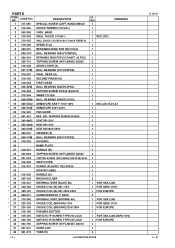
... 1 FOR EUROPE CARBON BRUSH (1 PAIR) 2 INTERNAL WIRE (BROWN) 86L 1 FOR USA,CAN CHOKE COIL (BROWN) 110V 1 FOR GBR (110V) CHOKE COIL (BROWN) 220V-240V 1 FOR EUROPE PUSHING BUTTON 1 SWITCH (1P SCREW TYPE) W/LOCK 1 FOR USA,CAN,GBR (110V) SWITCH (1P SCREW TYPE) W/LOCK 1 FOR EUROPE TAPPING SCREW (W/FLANGE) D4X16 2 CORD CLIP 1 TUBE (D) 2 --- 2 --- * ALTERNATIVE PARTS D 10VG 8 -- 01 USED 1 REMARKS CHUCK WRENCH 10VLR-J 1 VINYL BAND 1 DRILL CHUCK 10VLR-J 1 INCLUD.2 DRILL CHUCK 10VLRD-N (W/O CHUCK WRENCH) 1 SPINDLE (A) 1 RETAINING RING...
... 1 FOR EUROPE CARBON BRUSH (1 PAIR) 2 INTERNAL WIRE (BROWN) 86L 1 FOR USA,CAN CHOKE COIL (BROWN) 110V 1 FOR GBR (110V) CHOKE COIL (BROWN) 220V-240V 1 FOR EUROPE PUSHING BUTTON 1 SWITCH (1P SCREW TYPE) W/LOCK 1 FOR USA,CAN,GBR (110V) SWITCH (1P SCREW TYPE) W/LOCK 1 FOR EUROPE TAPPING SCREW (W/FLANGE) D4X16 2 CORD CLIP 1 TUBE (D) 2 --- 2 --- * ALTERNATIVE PARTS D 10VG 8 -- 01 USED 1 REMARKS CHUCK WRENCH 10VLR-J 1 VINYL BAND 1 DRILL CHUCK 10VLR-J 1 INCLUD.2 DRILL CHUCK 10VLRD-N (W/O CHUCK WRENCH) 1 SPINDLE (A) 1 RETAINING RING...
Parts List
Page 4
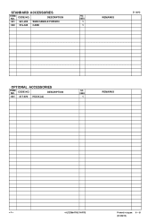
STANDARD ACCESSORIES ITEM NO. DESCRIPTION NO. USED 601 317-676 HOOK (A) 1 REMARKS --- 4 --- * ALTERNATIVE PARTS Printed in Japan 8 -- 01 (010821N) DESCRIPTION NO. CODE NO. USED 501 981-205 SIDE HANDLE FOR M10 1 502 319-543 CASE 1 REMARKS D 10VG OPTIONAL ACCESSORIES ITEM NO. CODE NO.
STANDARD ACCESSORIES ITEM NO. DESCRIPTION NO. USED 601 317-676 HOOK (A) 1 REMARKS --- 4 --- * ALTERNATIVE PARTS Printed in Japan 8 -- 01 (010821N) DESCRIPTION NO. CODE NO. USED 501 981-205 SIDE HANDLE FOR M10 1 502 319-543 CASE 1 REMARKS D 10VG OPTIONAL ACCESSORIES ITEM NO. CODE NO.

