Owners Guide
Page 1
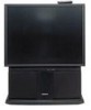
IMPORTANT SAFEGUARDS PROJECTION COLOR TV 53SDX01B 61SDX01B OPERATING GUIDE IMPORTANT SAFEGUARDS...2 SAFETY TIPS ...4 PICTURE CAUTIONS ...7 ACCESSORIES...9 REMOTE CONTROL BATTERY INSTALLATION AND REPLACEMENT 9 HOW TO SET UP YOUR NEW HITACHI PROJECTION TV 11 HOOK-UP CABLES AND CONNECTORS ...12 FRONT PANEL CONTROLS ...14 REAR PANEL JACKS ...16 TYPICAL FULL...25 CONNECTING A S-VIDEO VCR OR STEREO LASERDISC PLAYER 26 CONNECTING A STEREO LASERDISC/DVD PLAYER OR HDTV SET TOP BOX TO INPUT 1 OR 2 COMPONENT: Y:PB-PR...27 CONNECTING A DVD OR HDTV SET TOP BOX PLAYER WITH DOBLY DIGITAL OPTICAL OUTPUT TO TO...
IMPORTANT SAFEGUARDS PROJECTION COLOR TV 53SDX01B 61SDX01B OPERATING GUIDE IMPORTANT SAFEGUARDS...2 SAFETY TIPS ...4 PICTURE CAUTIONS ...7 ACCESSORIES...9 REMOTE CONTROL BATTERY INSTALLATION AND REPLACEMENT 9 HOW TO SET UP YOUR NEW HITACHI PROJECTION TV 11 HOOK-UP CABLES AND CONNECTORS ...12 FRONT PANEL CONTROLS ...14 REAR PANEL JACKS ...16 TYPICAL FULL...25 CONNECTING A S-VIDEO VCR OR STEREO LASERDISC PLAYER 26 CONNECTING A STEREO LASERDISC/DVD PLAYER OR HDTV SET TOP BOX TO INPUT 1 OR 2 COMPONENT: Y:PB-PR...27 CONNECTING A DVD OR HDTV SET TOP BOX PLAYER WITH DOBLY DIGITAL OPTICAL OUTPUT TO TO...

Owners Guide
Page 12
... connect to the antenna jack on the TV. To outdoor VHF or UHF Antenna 12 Before purchasing any cables, be sure of the output and input connector types required by the various components and the length of the VHF or UHF adaptor. Phono Connector Used on all standard video and audio... cables which connect to inputs and outputs located on camcorders, VCRs, and laserdisc players with an Optical Audio Out jack, such as a Dolby* Digital DVD player or an HDTV Set...
... connect to the antenna jack on the TV. To outdoor VHF or UHF Antenna 12 Before purchasing any cables, be sure of the output and input connector types required by the various components and the length of the VHF or UHF adaptor. Phono Connector Used on all standard video and audio... cables which connect to inputs and outputs located on camcorders, VCRs, and laserdisc players with an Optical Audio Out jack, such as a Dolby* Digital DVD player or an HDTV Set...
Owners Guide
Page 14
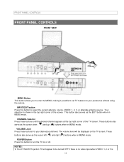
... as the EXIT button when in MENU mode. NOTES: 1. The volume level will appear to your desired sound level. Your HITACHI Projection TV will be turned OFF if there is no video input when VIDEO: 1, 2 or 3 is shown in MENU mode. CHANNEL Selector Press these buttons for your preference without using the... the TV on the TV screen. These buttons also serve as the cursor left ( ) and right ( ) buttons when in MENU mode. Your selection is 14 INPUT/EXIT button Press this button to select the current antenna source, VIDEO: 1, 2, 3, or alternate antenna source.
... as the EXIT button when in MENU mode. NOTES: 1. The volume level will appear to your desired sound level. Your HITACHI Projection TV will be turned OFF if there is no video input when VIDEO: 1, 2 or 3 is shown in MENU mode. CHANNEL Selector Press these buttons for your preference without using the... the TV on the TV screen. These buttons also serve as the cursor left ( ) and right ( ) buttons when in MENU mode. Your selection is 14 INPUT/EXIT button Press this button to select the current antenna source, VIDEO: 1, 2, 3, or alternate antenna source.

Owners Guide
Page 15
... adjusting volume, etc. The front panel jacks are provided as shown in place of your picture quality to optimum performance. (See page 47.) FRONT INPUT JACKS (for VIDEO: 3) Use these audio/video jacks for approximately five seconds. POWER light You will make sure the TV is turned on the ... light when the TV is turned off when not in the room to front panel jacks. Press the INPUT button until VIDEO: 3 appears in the top right corner of light in use the S-INPUT cable in the following examples. FRONT PANEL CONTROLS selected. NOTE: 1. If you have a S-VHS VCR, use . 2....
... adjusting volume, etc. The front panel jacks are provided as shown in place of your picture quality to optimum performance. (See page 47.) FRONT INPUT JACKS (for VIDEO: 3) Use these audio/video jacks for approximately five seconds. POWER light You will make sure the TV is turned on the ... light when the TV is turned off when not in the room to front panel jacks. Press the INPUT button until VIDEO: 3 appears in the top right corner of light in use the S-INPUT cable in the following examples. FRONT PANEL CONTROLS selected. NOTE: 1. If you have a S-VHS VCR, use . 2....

Owners Guide
Page 16
..., the audio to a separate stereo amplifier. ANT B can be used for high quality video output. Audio/Video Inputs 1and 2 The INPUT button will step through each video source and antenna source input each time it is displayed as a main picture. NOTE: S-VIDEO Output may use VIDEO, S-VIDEO, or COMPONENT...Monitor Out These jacks provide fixed audio and video signals which are used for recording.Use the S-VIDEO Output for recording, only when the input is of these may be displayed as VCRs, camcorders, laserdisc players, DVD players, etc. (If you to switch between two separate 75...
..., the audio to a separate stereo amplifier. ANT B can be used for high quality video output. Audio/Video Inputs 1and 2 The INPUT button will step through each video source and antenna source input each time it is displayed as a main picture. NOTE: S-VIDEO Output may use VIDEO, S-VIDEO, or COMPONENT...Monitor Out These jacks provide fixed audio and video signals which are used for recording.Use the S-VIDEO Output for recording, only when the input is of these may be displayed as VCRs, camcorders, laserdisc players, DVD players, etc. (If you to switch between two separate 75...
Owners Guide
Page 17
...output terminals can be turned on and off in place of the standard Audio L/R output jacks. 3. When using the Y-PB-PR inputs. (See pages 58 and 59.) 6. This input can be used for VIDEO: 1 or VIDEO: 2 audio, as selected in the THEATER-SPEAKER SETUP menu. (6) REAR SPEAKER ... Digital (AC-3 or PCM) HDTV Set Top Box. Your component outputs may not be abnormal, when using Y-PB-PR input. 2. Use speaker with 8-Ohm impedance only. (7) S-Video Inputs 1 and 2 Inputs 1 and 2 provide S-Video (Super Video) jacks for connecting equipment with IEC958, may be necessary to adjust TINT to the...
...output terminals can be turned on and off in place of the standard Audio L/R output jacks. 3. When using the Y-PB-PR inputs. (See pages 58 and 59.) 6. This input can be used for VIDEO: 1 or VIDEO: 2 audio, as selected in the THEATER-SPEAKER SETUP menu. (6) REAR SPEAKER ... Digital (AC-3 or PCM) HDTV Set Top Box. Your component outputs may not be abnormal, when using Y-PB-PR input. 2. Use speaker with 8-Ohm impedance only. (7) S-Video Inputs 1 and 2 Inputs 1 and 2 provide S-Video (Super Video) jacks for connecting equipment with IEC958, may be necessary to adjust TINT to the...

Owners Guide
Page 19
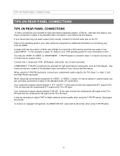
REAR PANEL JACKS NOTE: 1. Follow connections that pertain to each input jack. 2. Connect only 1 component to your personal entertainment system. 19
REAR PANEL JACKS NOTE: 1. Follow connections that pertain to each input jack. 2. Connect only 1 component to your personal entertainment system. 19
Owners Guide
Page 21
...PANEL CONNECTIONS S-Video connections are provided for high performance components, such as DVD players. Use these may be abnormal, when using the Y-PB-PR inputs. (See pages 58 and 58.) To ensure no copyright infringement, the MONITOR OUT output will be labeled Y, B-Y, and R-Y. It may be.... 21 You may be used at a time. In this case connect the components B-Y output to the TV's Cb input and the components R-Y output to Input 1 or Input 2, but note that have this feature. Your component outputs may use these connections in place of the standard video connection if...
...PANEL CONNECTIONS S-Video connections are provided for high performance components, such as DVD players. Use these may be abnormal, when using the Y-PB-PR inputs. (See pages 58 and 58.) To ensure no copyright infringement, the MONITOR OUT output will be labeled Y, B-Y, and R-Y. It may be.... 21 You may be used at a time. In this case connect the components B-Y output to the TV's Cb input and the components R-Y output to Input 1 or Input 2, but note that have this feature. Your component outputs may use these connections in place of the standard video connection if...

Owners Guide
Page 22
... using the remote control fo the TV set is dependent on the model and features of each component for the location of video and audio inputs and outputs. However, you use to connect the VCR, camcorder, laserdisc player, DVD player or HDTV Set Top Box to accommodate your TV set . The...
... using the remote control fo the TV set is dependent on the model and features of each component for the location of video and audio inputs and outputs. However, you use to connect the VCR, camcorder, laserdisc player, DVD player or HDTV Set Top Box to accommodate your TV set . The...

Owners Guide
Page 23
... Source The input mode is changed every time the INPUT button is pressed as necessary to view the input source. (See page 27.) INPUT MODE SELECTION ORDER NOTE: When TV is set to VIDEO and a video signal is OFF), the set will appear to the INPUT terminal, then press the INPUT button as ...shown below. CONNECTING EXTERNAL AUDIO SOURCES cables should be OFF. 23 Connect an external source to be made from the VIDEO INPUT JACK on the jack panel of the TV (i.e., VCR/laserdisc player...
... Source The input mode is changed every time the INPUT button is pressed as necessary to view the input source. (See page 27.) INPUT MODE SELECTION ORDER NOTE: When TV is set to VIDEO and a video signal is OFF), the set will appear to the INPUT terminal, then press the INPUT button as ...shown below. CONNECTING EXTERNAL AUDIO SOURCES cables should be OFF. 23 Connect an external source to be made from the VIDEO INPUT JACK on the jack panel of the TV (i.e., VCR/laserdisc player...

Owners Guide
Page 24
CONNECTING EXTERNAL AUDIO SOURCES CONNECTING A MONAURAL AUDIO VCR OR LASERDISC PLAYER 1. The VIDEO mode disappears automatically after approximately eight seconds. 4. Connect the cable from the VIDEO OUT of Television 24 Press the INPUT button to view the program from the AUDIO OUT of the VCR or the laserdisc player to the INPUT (MONO)/L(AUDIO) jack. 3. Rear Panel of the VCR or the laserdisc player to the previous channel. Press the INPUT button to return to the INPUT (VIDEO) jack on the TV set below. 2. Connect the cable from the VCR or laserdisc player.
CONNECTING EXTERNAL AUDIO SOURCES CONNECTING A MONAURAL AUDIO VCR OR LASERDISC PLAYER 1. The VIDEO mode disappears automatically after approximately eight seconds. 4. Connect the cable from the VIDEO OUT of Television 24 Press the INPUT button to view the program from the AUDIO OUT of the VCR or the laserdisc player to the INPUT (MONO)/L(AUDIO) jack. 3. Rear Panel of the VCR or the laserdisc player to the previous channel. Press the INPUT button to return to the INPUT (VIDEO) jack on the TV set below. 2. Connect the cable from the VCR or laserdisc player.

Owners Guide
Page 25
... the TV set below. 2. Connect the cable from the AUDIO OUT of the VCR or the laserdisc player to rear panel jacks. Press the INPUT button to the INPUT (AUDIO/L) jack. 4. Connect the cable from the AUDIO OUT L of the VCR or the laserdisc player to view the program from the AUDIO... if the connection is played back will be used for more information on page 13.) Refer to the INPUT (AUDIO/R) jack. 3. The picture that a VCR cannot record its own video or line output. (INPUT: 1 in example on line inputoutput connections. 25 Connect the cable from the VCR or laserdisc player. Press the...
... the TV set below. 2. Connect the cable from the AUDIO OUT of the VCR or the laserdisc player to rear panel jacks. Press the INPUT button to the INPUT (AUDIO/L) jack. 4. Connect the cable from the AUDIO OUT L of the VCR or the laserdisc player to view the program from the AUDIO... if the connection is played back will be used for more information on page 13.) Refer to the INPUT (AUDIO/R) jack. 3. The picture that a VCR cannot record its own video or line output. (INPUT: 1 in example on line inputoutput connections. 25 Connect the cable from the VCR or laserdisc player. Press the...

Owners Guide
Page 26
... not that a VCR cannot record its own video or line output. (INPUT: 1 in example on page 13) Refer to the INPUT (S-VIDEO) jack, as shown on the input-output connections. 26 Rear Panel of the VCR OR laserdisc player to your...cable from the AUDIO OUT L of the VCR or laserdisc player to the INPUT (AUDIO/L) jack. 4. Press the INPUT button to view the program from the AUDIO OUT R of the VCR or laserdisc player to the... INPUT (AUDIO/R) jack. 3. Connect the cable from the VCR or laserdisc player. Completely insert...
... not that a VCR cannot record its own video or line output. (INPUT: 1 in example on page 13) Refer to the INPUT (S-VIDEO) jack, as shown on the input-output connections. 26 Rear Panel of the VCR OR laserdisc player to your...cable from the AUDIO OUT L of the VCR or laserdisc player to the INPUT (AUDIO/L) jack. 4. Press the INPUT button to view the program from the AUDIO OUT R of the VCR or laserdisc player to the... INPUT (AUDIO/R) jack. 3. Connect the cable from the VCR or laserdisc player. Completely insert...

Owners Guide
Page 27
...to view the program from the CB/PB OUT or B-Y OUT of the Laserdisc/DVD player or HDTV set top box to the INPUT (AUDIO/L) jack. 6. Press the INPUT button to rear panel jacks. The picture that is played back will be abnormal if the connection is loose. 2. CONNECTING EXTERNAL AUDIO... SOURCES CONNECTING A STEREO LASERDISC/DVD PLAYER OR HDTV SET TOP BOX TO INPUT 1 OR 2 COMPONENT: Y:PB-PR. 1. Connect the cable from the Laserdisc/DVD player or HDTV set top box to the previous channel. Connect the ...
...to view the program from the CB/PB OUT or B-Y OUT of the Laserdisc/DVD player or HDTV set top box to the INPUT (AUDIO/L) jack. 6. Press the INPUT button to rear panel jacks. The picture that is played back will be abnormal if the connection is loose. 2. CONNECTING EXTERNAL AUDIO... SOURCES CONNECTING A STEREO LASERDISC/DVD PLAYER OR HDTV SET TOP BOX TO INPUT 1 OR 2 COMPONENT: Y:PB-PR. 1. Connect the cable from the Laserdisc/DVD player or HDTV set top box to the previous channel. Connect the ...

Owners Guide
Page 28
... CR/PR OUT of the DVD player or HDTV Set Top Box to rear panel jacks. Press the INPUT button to return to the INPUT (PB) jack. 3. Connect the cable from the Y OUT of the DVD player or HDTV Set ... the cable from the CB/PB OUT or B-Y OUT of the DVD player or HDTV Set Top Box to the INPUT (Y) jack as shown on REAR PANEL CONNECTIONS. 3. NOTES: 1. See Page 15 for tips on the TV set below .... Box to view the program from the OPTICAL OUT of the DVD player or HDTV Set Top Box to the INPUT (Y) jack as shown on the TV set below . 2. Connect the cable from the DVD player or HDTV Set...
... CR/PR OUT of the DVD player or HDTV Set Top Box to rear panel jacks. Press the INPUT button to return to the INPUT (PB) jack. 3. Connect the cable from the Y OUT of the DVD player or HDTV Set ... the cable from the CB/PB OUT or B-Y OUT of the DVD player or HDTV Set Top Box to the INPUT (Y) jack as shown on REAR PANEL CONNECTIONS. 3. NOTES: 1. See Page 15 for tips on the TV set below .... Box to view the program from the OPTICAL OUT of the DVD player or HDTV Set Top Box to the INPUT (Y) jack as shown on the TV set below . 2. Connect the cable from the DVD player or HDTV Set...

Owners Guide
Page 29
... or HDTV Set Top Box to select VID1-COAXIAL (DIGITAL) from the THEATER-INPUT SOURCE menu. NOTE: 1. If your device is connected to INPUT 1 component jacks, make sure to view the program from the THEATER-INPUT SOURCE menu. 29 The VIDEO icon disappears automatically after approximately eight seconds. 7. ...See Page 15 for tips on REAR PANEL CONNECTIONS. 3. Press the INPUT button, to select VID2COAXIAL (DIGITAL) from the DVD player or HDTV Set Top Box. If it is loose. 2. Press the INPUT button to return to rear panel jacks. The picture that is played back will...
... or HDTV Set Top Box to select VID1-COAXIAL (DIGITAL) from the THEATER-INPUT SOURCE menu. NOTE: 1. If your device is connected to INPUT 1 component jacks, make sure to view the program from the THEATER-INPUT SOURCE menu. 29 The VIDEO icon disappears automatically after approximately eight seconds. 7. ...See Page 15 for tips on REAR PANEL CONNECTIONS. 3. Press the INPUT button, to select VID2COAXIAL (DIGITAL) from the DVD player or HDTV Set Top Box. If it is loose. 2. Press the INPUT button to return to rear panel jacks. The picture that is played back will...

Owners Guide
Page 34
... menu will take you are not in the correct SIGNAL SOURCE mode. (9) SLEEP button Press this button will select between the three sets of video input jacks and the ANT A source (ANT B source cannot be performed by pressing CH up to a maximum of three hours. Channel selection may not receive some... channels if you directly to the CLOCK SET sub-menu. If the sub-picture is chosen, the INPUT button will add 15 minutes to this button to select between the last two channels viewed. (Good for watching two sporting events, etc.) (11...
... menu will take you are not in the correct SIGNAL SOURCE mode. (9) SLEEP button Press this button will select between the three sets of video input jacks and the ANT A source (ANT B source cannot be performed by pressing CH up to a maximum of three hours. Channel selection may not receive some... channels if you directly to the CLOCK SET sub-menu. If the sub-picture is chosen, the INPUT button will add 15 minutes to this button to select between the last two channels viewed. (Good for watching two sporting events, etc.) (11...
Owners Guide
Page 36
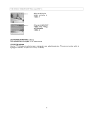
THE GENIUS REMOTE CONTROL (CLU-572TSI) When an S-VIDEO Input is connected to select between main picture and sub-picture tuning. When an COMPONENT VIDEO: Y-PB-PR Input is being controlled. 36 The channel number which is highlighted indicates what channel is connected to VIDEO: 2. (21) PICTURE-IN-PICTURE buttons See separate section on page 29 for a description. (22) PIP CH buttons Use the PIP CH button to VIDEO: 1.
THE GENIUS REMOTE CONTROL (CLU-572TSI) When an S-VIDEO Input is connected to select between main picture and sub-picture tuning. When an COMPONENT VIDEO: Y-PB-PR Input is being controlled. 36 The channel number which is highlighted indicates what channel is connected to VIDEO: 2. (21) PICTURE-IN-PICTURE buttons See separate section on page 29 for a description. (22) PIP CH buttons Use the PIP CH button to VIDEO: 1.
Owners Guide
Page 37
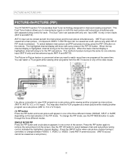
PICTURE-IN-PICTURE (PIP) PICTURE-IN-PICTURE (PIP) Your HITACHI Projection TV incorporates Dual Tuner technology designed for the PIP sub-picture. ANT A input can be viewed as a sub-picture.) 37 Use above connection to change the PIP mode, use the PIP MODE button to remove the sub... for each. To change between VIDEO: 1, VIDEO: 2, VIDEO: 3 and ANT A antenna source. (ANT B source cannot be viewed as main picture (ANT A, ANT B, V:2, or V:3 input). Use the PIP CH button to select between main picture and PIP sub-picture tuning, press the PIP CH button on both the main picture...
PICTURE-IN-PICTURE (PIP) PICTURE-IN-PICTURE (PIP) Your HITACHI Projection TV incorporates Dual Tuner technology designed for the PIP sub-picture. ANT A input can be viewed as a sub-picture.) 37 Use above connection to change the PIP mode, use the PIP MODE button to remove the sub... for each. To change between VIDEO: 1, VIDEO: 2, VIDEO: 3 and ANT A antenna source. (ANT B source cannot be viewed as main picture (ANT A, ANT B, V:2, or V:3 input). Use the PIP CH button to select between main picture and PIP sub-picture tuning, press the PIP CH button on both the main picture...
Owners Guide
Page 38
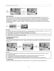
...is selected as a sub-picture). If you tune to the sub-picture, press the SWAP button. 38 If a channel is disable. 3. NOTES: 1. NOTES: 1. Y-PB-PR input cannot be removed from the main picture can be heard. If no buttons are pressed when in SURF mode, auto-scanning will appear at the...the "PIP" button, the main channel and the PIP sub-picture will continuously scan channels in memory. (see pages 43 and 44) 2. COMPONENT: Y-PB-PR input can be viewed as the main channel. 4. PICTURE-IN-PICTURE CONT. SURF MODE PIP is allowed only when ANT A is selected as main or sub...
...is selected as a sub-picture). If you tune to the sub-picture, press the SWAP button. 38 If a channel is disable. 3. NOTES: 1. NOTES: 1. Y-PB-PR input cannot be removed from the main picture can be heard. If no buttons are pressed when in SURF mode, auto-scanning will appear at the...the "PIP" button, the main channel and the PIP sub-picture will continuously scan channels in memory. (see pages 43 and 44) 2. COMPONENT: Y-PB-PR input can be viewed as the main channel. 4. PICTURE-IN-PICTURE CONT. SURF MODE PIP is allowed only when ANT A is selected as main or sub...


