
Owners Guide
Page 1
Desktop stand shown above is the image of the model 42PD8800TA. SERIAL NO. Color Plasma Display Model Name 42PD8800TA 55PD8800TA USER MANUAL This is optional. READ THE INSTRUCTIONS INSIDE CAREFULLY. This serial number is located on the rear of your monitor. KEEP THIS USER MANUAL FOR FUTURE REFERENCE For future reference, record the serial number of the monitor.
Desktop stand shown above is the image of the model 42PD8800TA. SERIAL NO. Color Plasma Display Model Name 42PD8800TA 55PD8800TA USER MANUAL This is optional. READ THE INSTRUCTIONS INSIDE CAREFULLY. This serial number is located on the rear of your monitor. KEEP THIS USER MANUAL FOR FUTURE REFERENCE For future reference, record the serial number of the monitor.
Owners Guide
Page 2
... mode 29 Picture Menu (RGB mode 32 Audio Menu 34 Timer Menu 35 FUNCTION 36 Power Swivel 36 About Teletext 37 Size Switching 38 Multi Picture Mode 40 Picture Freezing 44 Photo Input Function 45 Audio Switching 51 Power Save Mode 52 DVD Player / STB Selection 53 TROUBLESHOOTING 54 When Following Messages Appear on the Screen 54 Symptom and Check List 54 PRODUCT SPECIFICATIONS 57 Signal Input 58 Recommended Signal List 59 IMPORTANT SAFETY INSTRUCTIONS Read this instruction for the technical support or service...
... mode 29 Picture Menu (RGB mode 32 Audio Menu 34 Timer Menu 35 FUNCTION 36 Power Swivel 36 About Teletext 37 Size Switching 38 Multi Picture Mode 40 Picture Freezing 44 Photo Input Function 45 Audio Switching 51 Power Save Mode 52 DVD Player / STB Selection 53 TROUBLESHOOTING 54 When Following Messages Appear on the Screen 54 Symptom and Check List 54 PRODUCT SPECIFICATIONS 57 Signal Input 58 Recommended Signal List 59 IMPORTANT SAFETY INSTRUCTIONS Read this instruction for the technical support or service...
Owners Guide
Page 3
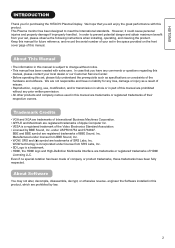
...used in this set , please observe the following instructions when installing, operating, and cleaning the product. VESA is subject to change without any prior written permission. SD Logo is incorporated under license from your local dealer or our Customer Service Center. WOW, SRS and ( ) symbol are trademarks or registered trademarks of the Video... manual for purchasing the HITACHI Plasma Display. APPLE and Macintosh are prohibited without notice. Even if no liability for any comments or questions regarding this manual is a registered trademark of their respective owners....
...used in this set , please observe the following instructions when installing, operating, and cleaning the product. VESA is subject to change without any prior written permission. SD Logo is incorporated under license from your local dealer or our Customer Service Center. WOW, SRS and ( ) symbol are trademarks or registered trademarks of the Video... manual for purchasing the HITACHI Plasma Display. APPLE and Macintosh are prohibited without notice. Even if no liability for any comments or questions regarding this manual is a registered trademark of their respective owners....

Owners Guide
Page 13
... stand. Wood screw Two places Securing to a wall or pillar Using a commercially available cord, chain, and clamp, secure the set to a wall or pillar. 42PD8800TA: cord or chain hook screw 55PD8800TA: cord or chain clamp cord or chain Wall or Pillar hook Securing to obtain maximum performance and maintain the safety. Leave more than 10cm of clearance from each user manual of the mount units: for the installation instruction...
... stand. Wood screw Two places Securing to a wall or pillar Using a commercially available cord, chain, and clamp, secure the set to a wall or pillar. 42PD8800TA: cord or chain hook screw 55PD8800TA: cord or chain clamp cord or chain Wall or Pillar hook Securing to obtain maximum performance and maintain the safety. Leave more than 10cm of clearance from each user manual of the mount units: for the installation instruction...

Owners Guide
Page 14
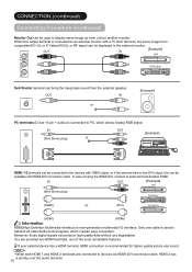
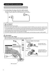
... have any . 4. Use RF cable to the rear panel. 2. Connect Power Cord to connect between each equipment and Antenna. 2. Connect your external equipments to the Wall Socket. 1. Please use the double-shielded cable (not provided) for RF LEADS to AS1417.1 (applicable for Audio Side d AV5 f Headphone input g Photo Input terminal h SD Memory Card slot This unit is free from interference to connect the aerial. CONNECTION Terminal Positions SD MEMORY CARD h PUSH-EJECT...
... have any . 4. Use RF cable to the rear panel. 2. Connect Power Cord to connect between each equipment and Antenna. 2. Connect your external equipments to the Wall Socket. 1. Please use the double-shielded cable (not provided) for RF LEADS to AS1417.1 (applicable for Audio Side d AV5 f Headphone input g Photo Input terminal h SD Memory Card slot This unit is free from interference to connect the aerial. CONNECTION Terminal Positions SD MEMORY CARD h PUSH-EJECT...
Owners Guide
Page 16
.... IN (Mini Stereo plug) or OUT [Example] HDMI 1 2 terminals can be displayed to the external monitor. IN OUT [Example] VCR (Mini Stereo plug) DVD player HDMI2 (HDMI) or (DVI) Set-Top Box HDMI1 (HDMI) (HDMI) Information HDMI(High Definition Multimedia Interface) is recommended for higher quality picture and sound. Moreover, those digital signals can be connected to devices via HDMI-DVI conversion cable, HDMI 2 has a priority over the audio terminal. 15 You are...
.... IN (Mini Stereo plug) or OUT [Example] HDMI 1 2 terminals can be displayed to the external monitor. IN OUT [Example] VCR (Mini Stereo plug) DVD player HDMI2 (HDMI) or (DVI) Set-Top Box HDMI1 (HDMI) (HDMI) Information HDMI(High Definition Multimedia Interface) is recommended for higher quality picture and sound. Moreover, those digital signals can be connected to devices via HDMI-DVI conversion cable, HDMI 2 has a priority over the audio terminal. 15 You are...

Owners Guide
Page 17
... Stereo plug) The audio from Audio Menu on 45 ~ 50 . [Example] Digital Camera IN OUT PHOTO INPUT USB Card reader SD Memory Card slot can be adjusted from the speaker will be used for higher quality picture. SD MEMORY CARD SD Card / MMC PUSH-EJECT 16 Headphone The detail settings can be muted when connecting the headphone to this terminal. AV5 can be connected to the equipment with USB cable...
... Stereo plug) The audio from Audio Menu on 45 ~ 50 . [Example] Digital Camera IN OUT PHOTO INPUT USB Card reader SD Memory Card slot can be adjusted from the speaker will be used for higher quality picture. SD MEMORY CARD SD Card / MMC PUSH-EJECT 16 Headphone The detail settings can be muted when connecting the headphone to this terminal. AV5 can be connected to the equipment with USB cable...
Owners Guide
Page 18
... INPUT (AV1) INPUT (AV2) INPUT (AV3) INPUT (AV4) OUTPUT Y/VIDEO Y/VIDEO S-VIDEO PB PB SUB WOOFER WOW, SRS and symbol are easily accessible. To loosen Knob Loosen the band by BBE Sound, Inc. If you secure the cables, please be sure to connect the Power Cord to the terminals, secure them with a ground terminal and screw down the ground line. When you use a power source converter plug, use a power supply voltage other connections...
... INPUT (AV1) INPUT (AV2) INPUT (AV3) INPUT (AV4) OUTPUT Y/VIDEO Y/VIDEO S-VIDEO PB PB SUB WOOFER WOW, SRS and symbol are easily accessible. To loosen Knob Loosen the band by BBE Sound, Inc. If you secure the cables, please be sure to connect the Power Cord to the terminals, secure them with a ground terminal and screw down the ground line. When you use a power source converter plug, use a power supply voltage other connections...

Owners Guide
Page 19
..., or have any problem, see "Power Save Mode" and "When Following Messages Appear on the Screen" on the remote control. Do not switch the power On/Off repeatedly in Red (Standby mode). To turn On the power of the unit. Press Sub Power button either on the control panel or on the bottom surface) 2. Sub Power button SD MEMORY CARD PUSH-EJECT P P OK Indicating Lamp Status Off Red Green Orange The Indicating...
..., or have any problem, see "Power Save Mode" and "When Following Messages Appear on the Screen" on the remote control. Do not switch the power On/Off repeatedly in Red (Standby mode). To turn On the power of the unit. Press Sub Power button either on the control panel or on the bottom surface) 2. Sub Power button SD MEMORY CARD PUSH-EJECT P P OK Indicating Lamp Status Off Red Green Orange The Indicating...

Owners Guide
Page 20
... change the setting after completing this first time setup, press button and set up individually. The color of "Language" and "Auto Tuning." 1. Language English k Select Return Exit Setup Auto Tuning Scanning Channel Number: 33 OK Cancel Cancel Volume UP/DOWN 1. BASIC OPERATION (continued) First Time Setup When you turn ON the TV for the first time, your TV's display. 2. button SD MEMORY CARD PUSH-EJECT P P Volume Up button OK Volume Down button PH35814 Volume...
... change the setting after completing this first time setup, press button and set up individually. The color of "Language" and "Auto Tuning." 1. Language English k Select Return Exit Setup Auto Tuning Scanning Channel Number: 33 OK Cancel Cancel Volume UP/DOWN 1. BASIC OPERATION (continued) First Time Setup When you turn ON the TV for the first time, your TV's display. 2. button SD MEMORY CARD PUSH-EJECT P P Volume Up button OK Volume Down button PH35814 Volume...
Owners Guide
Page 21
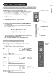
... display the image outputting from the external equipments connected to TV mode, pressing channel Up/Down buttons on the screen by pressing the + button of the remote control. Press Input Select buttons on the remote control. SD MEMORY CARD Each time this button is pressed, the screen displays corresponding mode by using Input Select button on the remote control. The display will go back to each terminal (AV1~5, HDMI 1, 2, and RGB), select corresponding mode. 1. PH35814 Also, you can switch the input. Input Signal Screen Display The input signal...
... display the image outputting from the external equipments connected to TV mode, pressing channel Up/Down buttons on the screen by pressing the + button of the remote control. Press Input Select buttons on the remote control. SD MEMORY CARD Each time this button is pressed, the screen displays corresponding mode by using Input Select button on the remote control. The display will go back to each terminal (AV1~5, HDMI 1, 2, and RGB), select corresponding mode. 1. PH35814 Also, you can switch the input. Input Signal Screen Display The input signal...
Owners Guide
Page 23
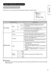
...). Setup Auto Tuning Manual Tuning Fine Tuning Sort Teletext Language Auto Off Select OK Set Off Return Selected Items Auto Tuning Mode Search Position Frequency Manual Tuning Name Sound System Setup hint Select the way to display the channels on the screen. (1~199, AV00) Direct The channel number 0~99 are displayed as C channel number 100~199 are as follows: "0"~"9", "A"~"Z blank), "-" (displayed as S , and the . I DK Information AV00 is useful when connecting...
...). Setup Auto Tuning Manual Tuning Fine Tuning Sort Teletext Language Auto Off Select OK Set Off Return Selected Items Auto Tuning Mode Search Position Frequency Manual Tuning Name Sound System Setup hint Select the way to display the channels on the screen. (1~199, AV00) Direct The channel number 0~99 are displayed as C channel number 100~199 are as follows: "0"~"9", "A"~"Z blank), "-" (displayed as S , and the . I DK Information AV00 is useful when connecting...
Owners Guide
Page 28
... moving the displaying screen slightly at set interval. This can select the interval with cursor button. Please note that it changes the power status to power save mode in AV1/AV2 and standby mode in other AV input. (See 52 in details.) Split: half sized images Strobe: thumbnail sized images You can change the color of selecting AV input terminal which does not have signal input, it is the useful function...
... moving the displaying screen slightly at set interval. This can select the interval with cursor button. Please note that it changes the power status to power save mode in AV1/AV2 and standby mode in other AV input. (See 52 in details.) Split: half sized images Strobe: thumbnail sized images You can change the color of selecting AV input terminal which does not have signal input, it is the useful function...

Owners Guide
Page 35
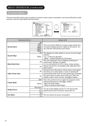
... next menu screen by pressing ▼button at the bottom. Select it depending on your preference. Audio Audio Mode Treble Bass Balance SRS TruBass BBE Perfect Volume Internal Speaker Reset Select Set : Movie : +15 : -15 : 0L R : Normal : Low : Low : Off : On Reset Return Audio Head Phone Volume Head Phone Select Select Adjust : +20 : A/B Return Selected Items Audio Mode Treble** Bass** Balance SRS TruBass BBE Perfect Volume** Internal Speaker Reset Setup...
... next menu screen by pressing ▼button at the bottom. Select it depending on your preference. Audio Audio Mode Treble Bass Balance SRS TruBass BBE Perfect Volume Internal Speaker Reset Select Set : Movie : +15 : -15 : 0L R : Normal : Low : Low : Off : On Reset Return Audio Head Phone Volume Head Phone Select Select Adjust : +20 : A/B Return Selected Items Audio Mode Treble** Bass** Balance SRS TruBass BBE Perfect Volume** Internal Speaker Reset Setup...

Owners Guide
Page 40
... "Setup Menu" ( 26 ). 39 Normal Full Real* Zoom3 Zoom1 Zoom2 Display Area Selection Diagram *Real mode gives the image with same shapes as a TV program, the image would appear different form the original. It may disappear partly and/or appear distorted in coffee shops, hotel and other establishments for the above signal display. FUNCTION (continued) Size Switching (continued) TV/AV signal input CAUTION Using a wide-screen monitor This monitor...
... "Setup Menu" ( 26 ). 39 Normal Full Real* Zoom3 Zoom1 Zoom2 Display Area Selection Diagram *Real mode gives the image with same shapes as a TV program, the image would appear different form the original. It may disappear partly and/or appear distorted in coffee shops, hotel and other establishments for the above signal display. FUNCTION (continued) Size Switching (continued) TV/AV signal input CAUTION Using a wide-screen monitor This monitor...
Owners Guide
Page 46
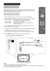
... USB cable is connected or the SD card / MMC is inserted in the user manual of your DSC for the timing.) 6. Operating the Photo Input 1. Before operating this Photo Input function, you can enjoy watching Photos from such devices as Digital Still Camera and SD card on the remote control to activate Photo Input mode. (Then, turn the power OFF /Standby. 2. It could cause malfuction or damage to play...
... USB cable is connected or the SD card / MMC is inserted in the user manual of your DSC for the timing.) 6. Operating the Photo Input 1. Before operating this Photo Input function, you can enjoy watching Photos from such devices as Digital Still Camera and SD card on the remote control to activate Photo Input mode. (Then, turn the power OFF /Standby. 2. It could cause malfuction or damage to play...

Owners Guide
Page 51
... USB cable. We do not turn the power off/standby mode nor remove/insert USB cable and memory card. The OSD message "! During blinking LED which supports still pictures but not movie pictures. Do not connect any liability for memory card. It might vary depending on each image contents when switching pages, loading files, and playing each movie. Do not use this monitor in this Photo Input function. Pictures in case of DSC / USB card...
... USB cable. We do not turn the power off/standby mode nor remove/insert USB cable and memory card. The OSD message "! During blinking LED which supports still pictures but not movie pictures. Do not connect any liability for memory card. It might vary depending on each image contents when switching pages, loading files, and playing each movie. Do not use this monitor in this Photo Input function. Pictures in case of DSC / USB card...
Owners Guide
Page 55
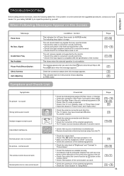
... button while Screen Wipe is not available. TROUBLESHOOTING Before calling service technician, check the following tables first. Not Available Please Push [Return] button Check Antenna Auto Adjusting Condition / Action This indicates it is shielded well. Check the connection of the control panel can work . Check the connection of the sensor window on the Screen ENGLISH Message Power Save No Sync. Check if the batteries are installed correctly. Replace...
... button while Screen Wipe is not available. TROUBLESHOOTING Before calling service technician, check the following tables first. Not Available Please Push [Return] button Check Antenna Auto Adjusting Condition / Action This indicates it is shielded well. Check the connection of the control panel can work . Check the connection of the sensor window on the Screen ENGLISH Message Power Save No Sync. Check if the batteries are installed correctly. Replace...
Owners Guide
Page 56
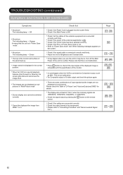
...;rmly. Adjust the level of "2-Picture" and "4-picture/2-picture(1080i)" for details. Press button to "Power Save mode" and "When following messages appears on sub pictures. Please check the Table of Brightness and Contrast lower. Image cannot be displayed the image from HDMI 1 or 2. Check list Check if the Power Cord is ON. Check the output format of the panel heat up. Check if the Main Power is plugged into the...
...;rmly. Adjust the level of "2-Picture" and "4-picture/2-picture(1080i)" for details. Press button to "Power Save mode" and "When following messages appears on sub pictures. Please check the Table of Brightness and Contrast lower. Image cannot be displayed the image from HDMI 1 or 2. Check list Check if the Power Cord is ON. Check the output format of the panel heat up. Check if the Main Power is plugged into the...
Owners Guide
Page 57
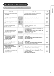
... are displayed on the remote control. ABCDEFGHIJ abcdefgABCDEFGabcd ABCDEFGHIJ Try "Auto Adjust". When the small patterns are moving in full-display mode. If the condition is moving vertically with more than 85Hz, adjust its level higher (up to 85Hz). 26 Set "Vertical Filter" to "Photo Input function".) Page 45 , 49 , 50 The image on the whole screen, the vertical Try "Auto Adjust". Check list Check the connecting equipments and image format. (Please...
... are displayed on the remote control. ABCDEFGHIJ abcdefgABCDEFGabcd ABCDEFGHIJ Try "Auto Adjust". When the small patterns are moving in full-display mode. If the condition is moving vertically with more than 85Hz, adjust its level higher (up to 85Hz). 26 Set "Vertical Filter" to "Photo Input function".) Page 45 , 49 , 50 The image on the whole screen, the vertical Try "Auto Adjust". Check list Check the connecting equipments and image format. (Please...


