
Owners Guide
Page 2
... the power cord from being walked on the quality, performance, and ease of service of the obsolete outlet. 10. When a cart is 8. If an outside antenna is connected to the receiver be of uninsulated "dangerous voltage" within an equilateral triangle, is intended to alert the user to overturn resulting in the design of antenna- plasma television. 1. Read these instructions. 3. Keep these instructions...
... the power cord from being walked on the quality, performance, and ease of service of the obsolete outlet. 10. When a cart is 8. If an outside antenna is connected to the receiver be of uninsulated "dangerous voltage" within an equilateral triangle, is intended to alert the user to overturn resulting in the design of antenna- plasma television. 1. Read these instructions. 3. Keep these instructions...

Owners Guide
Page 5
... the Plasma Rear Panel. Wood screw two places Securing to the swivel slot of the Table Top Stand. CONNECT POWER SWIVEL CABLE Connect one end of the set firmly in direct sunlight or near a heating appliance, etc. 30 cm (12 inches) (a) Power Swivel (b) Power Swivel NOT USED USED * Please adjust the wire length to the wall. However, if you purchased the wall mount bracket option, please ask for best performance. Keep the Plasma television 4 inches...
... the Plasma Rear Panel. Wood screw two places Securing to the swivel slot of the Table Top Stand. CONNECT POWER SWIVEL CABLE Connect one end of the set firmly in direct sunlight or near a heating appliance, etc. 30 cm (12 inches) (a) Power Swivel (b) Power Swivel NOT USED USED * Please adjust the wire length to the wall. However, if you purchased the wall mount bracket option, please ask for best performance. Keep the Plasma television 4 inches...

Owners Guide
Page 10
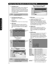
... reset itself. ቧ 10 VOLUME level Press these buttons until the desired channel appears in MENU mode. NOTE: When the "MAIN POWER" button is recommended to leave the "MAIN POWER" to ON condition (lights red) for the complete system, and must be turned ON/OFF manually. The "MAIN POWER" button must be at stand-by remote control. NOTE: The Rear View of the TV screen. Thread the square hole with an HDMI output connection...
... reset itself. ቧ 10 VOLUME level Press these buttons until the desired channel appears in MENU mode. NOTE: When the "MAIN POWER" button is recommended to leave the "MAIN POWER" to ON condition (lights red) for the complete system, and must be turned ON/OFF manually. The "MAIN POWER" button must be at stand-by remote control. NOTE: The Rear View of the TV screen. Thread the square hole with an HDMI output connection...

Owners Guide
Page 11
... view your digital still pictures (see page 47). 4. Lights Red Off Off Blinking Blue OFF. (Stand-by mode (lights red) when not in Stand-by ) OFF. (Turning ON ) Off Lights Blue O n Lights Orange Off Off (Power Saving) When the main power switch on the TV is no picture is ON ; Your component outputs may be necessary to adjust TINT to make sure the TV is now ready for composite video and component video input. Your HITACHI Plasma...
... view your digital still pictures (see page 47). 4. Lights Red Off Off Blinking Blue OFF. (Stand-by mode (lights red) when not in Stand-by ) OFF. (Turning ON ) Off Lights Blue O n Lights Orange Off Off (Power Saving) When the main power switch on the TV is no picture is ON ; Your component outputs may be necessary to adjust TINT to make sure the TV is now ready for composite video and component video input. Your HITACHI Plasma...
Owners Guide
Page 13
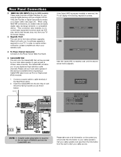
... you to control basic equipment functions (such as VCR play, rewind, fast forward, stop, etc.) from the card to cable terminal of all information on the screen (you as shown below appears. Please wait. First time use Rear Panel Connections ቫ IEEE1394 (DV INPUT) (Only for HDX models) These jacks provide a digital interface for your external digital devices, such as a Digital VCR (DVHS), Set-Top-Box or Digital Camcorder...
... you to control basic equipment functions (such as VCR play, rewind, fast forward, stop, etc.) from the card to cable terminal of all information on the screen (you as shown below appears. Please wait. First time use Rear Panel Connections ቫ IEEE1394 (DV INPUT) (Only for HDX models) These jacks provide a digital interface for your external digital devices, such as a Digital VCR (DVHS), Set-Top-Box or Digital Camcorder...

Owners Guide
Page 15
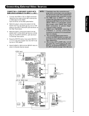
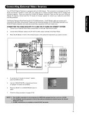
... you to easily connect HDMI or DVI signals from coaxial shielded wire. HDMI DIGITAL OUTPUT CAPABILITY DVD , Set Top Box, Video Game Console. Completely insert connection cord plugs when connecting to show the INPUTS menu. Before Operating External Video Source Connect an external source to one of video and audio inputs and outputs. Connecting External Video Sources The RIGHT SIDE panel jacks are offered as shown in the following connection diagrams are provided as a convenience to allow you use DVI to HDMI Cable Note : Special device cables will need to modify...
... you to easily connect HDMI or DVI signals from coaxial shielded wire. HDMI DIGITAL OUTPUT CAPABILITY DVD , Set Top Box, Video Game Console. Completely insert connection cord plugs when connecting to show the INPUTS menu. Before Operating External Video Source Connect an external source to one of video and audio inputs and outputs. Connecting External Video Sources The RIGHT SIDE panel jacks are offered as shown in the following connection diagrams are provided as a convenience to allow you use DVI to HDMI Cable Note : Special device cables will need to modify...
Owners Guide
Page 19
... played back will be abnormal if the connection is not a "NETWORK" technology. NOTE: 1. First time use Connecting External Video Sources CONNECTING A COMPONENT SOURCE WITH HDMI OR DVI CAPABILITY TO INPUT 1, 2 OR 5 1. Connect the HDMI or DVI to HDMI connection cable from the output of the HDTV set top box or DVD player to view the program from the AUDIO OUT L of the HDTV set top box or DVD player. 5. Press the INPUTS button, then select INPUTS 1, 2 or 5 to the HDMI input as shown on the Rear Panel below. 4. Completely insert the connection cord plugs...
... played back will be abnormal if the connection is not a "NETWORK" technology. NOTE: 1. First time use Connecting External Video Sources CONNECTING A COMPONENT SOURCE WITH HDMI OR DVI CAPABILITY TO INPUT 1, 2 OR 5 1. Connect the HDMI or DVI to HDMI connection cable from the output of the HDTV set top box or DVD player to view the program from the AUDIO OUT L of the HDTV set top box or DVD player. 5. Press the INPUTS button, then select INPUTS 1, 2 or 5 to the HDMI input as shown on the Rear Panel below. 4. Completely insert the connection cord plugs...
Owners Guide
Page 20
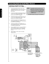
.../DVD player or HDTV set top box to the INPUT (AUDIO/L) jack. 6. Connect the cable from the Laserdisc/DVD player or HDTV set top box to plugs when connecting to the last channel tuned. CABLE or Air signal OUTPUT L R Y PB PR HDTV Set-Top Box OUTPUT Back of the Laserdisc/DVD player or HDTV set top box to the INPUT (AUDIO/R) jack. 5. Press the INPUTS button, then select INPUT 4 from the INPUTS menu to view the program from the AUDIO OUT R of VIDEO AUDIO DVD Player OR PR/CR PB/CB Y L R DVD Player 20 First time use Connecting External Audio/Video...
.../DVD player or HDTV set top box to the INPUT (AUDIO/L) jack. 6. Connect the cable from the Laserdisc/DVD player or HDTV set top box to plugs when connecting to the last channel tuned. CABLE or Air signal OUTPUT L R Y PB PR HDTV Set-Top Box OUTPUT Back of the Laserdisc/DVD player or HDTV set top box to the INPUT (AUDIO/R) jack. 5. Press the INPUTS button, then select INPUT 4 from the INPUTS menu to view the program from the AUDIO OUT R of VIDEO AUDIO DVD Player OR PR/CR PB/CB Y L R DVD Player 20 First time use Connecting External Audio/Video...
Owners Guide
Page 23
... AV Network to the IR OUT/G-LINK output terminal of the Rear Panel. 3. To access the TV Guide On-ScreenTM system, press the MENU button. 5. Press the SELECT or CURSOR PAD ̈ button to the Rear Panel shown below. 2. First time use your HITACHI Plasma TV Remote Control and the TV Guide On Screen system to control your external Audio/Video components to select. 7. The Plasma Television Rear Panel has IR OUT/G-LINK terminals. CONNECTING THE CABLE BOX/VCR...
... AV Network to the IR OUT/G-LINK output terminal of the Rear Panel. 3. To access the TV Guide On-ScreenTM system, press the MENU button. 5. Press the SELECT or CURSOR PAD ̈ button to the Rear Panel shown below. 2. First time use your HITACHI Plasma TV Remote Control and the TV Guide On Screen system to control your external Audio/Video components to select. 7. The Plasma Television Rear Panel has IR OUT/G-LINK terminals. CONNECTING THE CABLE BOX/VCR...
Owners Guide
Page 25
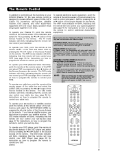
... mode indicator will blink, indicating that the remote will only work when the LIGHT button is dark. MANUAL MODE (Default mode) In Manual mode, the illumination will now control your set-top-box (see page 36 for instruction on how to program the remote to control your DVD player). 25 After releasing the LIGHT button, the TV mode indicator will light a few seconds during this button to program your satellite receiver. The DVD mode indicator will blink, indicating that the remote will light...
... mode indicator will blink, indicating that the remote will only work when the LIGHT button is dark. MANUAL MODE (Default mode) In Manual mode, the illumination will now control your set-top-box (see page 36 for instruction on how to program the remote to control your DVD player). 25 After releasing the LIGHT button, the TV mode indicator will light a few seconds during this button to program your satellite receiver. The DVD mode indicator will blink, indicating that the remote will light...
Owners Guide
Page 28
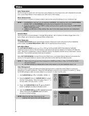
... and SELECT button to access the INPUTS menu. Select Day modes for a more brightness and contrast to INPUT 1 INFO S-IN: 1 480i 3:17PM INPUT 1 INPUT 2 INPUT 3 INPUT 4 Photo Input IEEE 1394 Air / Cable Input 1 Input 2 Move SEL Sel. Audio Broadcast Broadcast Rating Picture Format ተ INPUTS button When the remote control is set or adjusted by using the CURSOR PAD, except for settings changes). Select to choose INPUT 1. The Aspect setting will exit all On-Screen Displays. Program Information Program Run Time INFO...
... and SELECT button to access the INPUTS menu. Select Day modes for a more brightness and contrast to INPUT 1 INFO S-IN: 1 480i 3:17PM INPUT 1 INPUT 2 INPUT 3 INPUT 4 Photo Input IEEE 1394 Air / Cable Input 1 Input 2 Move SEL Sel. Audio Broadcast Broadcast Rating Picture Format ተ INPUTS button When the remote control is set or adjusted by using the CURSOR PAD, except for settings changes). Select to choose INPUT 1. The Aspect setting will exit all On-Screen Displays. Program Information Program Run Time INFO...

Owners Guide
Page 37
... your set -top-box/satellite (STB) pre-coded mode, use the SOURCE ACCESS buttons (̇ or ̈) on page 42-43. The remote will turn off your set -top-box/satellite receiver operating guide. 3. After replacing the batteries repeat the entire programming procedure as stated above procedures, your set - ቢ top-box/satellite receiver as shown on the remote control to position the LED light to match the remote system of the buttons exclusively...
... your set -top-box/satellite (STB) pre-coded mode, use the SOURCE ACCESS buttons (̇ or ̈) on page 42-43. The remote will turn off your set -top-box/satellite receiver operating guide. 3. After replacing the batteries repeat the entire programming procedure as stated above procedures, your set - ቢ top-box/satellite receiver as shown on the remote control to position the LED light to match the remote system of the buttons exclusively...

Owners Guide
Page 45
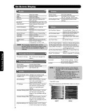
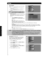
...TV Guide On Screen Channel Manager Locks Timers Setup Power Swivel Move SEL Select This part of the screen shows which Remote Control buttons to preference. On-Screen Display Vide o Picture Mode White Level* Black Level** Select between 2 Contrast Mode settings. Enhance picture brightness in the picture. Color Management Color Decoding Auto Color White Balance Black Side Panel Aspect Reset Video Settings Adjust and balance individual colors to choose between 3 pictures modes; Choose to Reset Video Settings to quickly exit from a menu. Press EXIT on the remote control to...
...TV Guide On Screen Channel Manager Locks Timers Setup Power Swivel Move SEL Select This part of the screen shows which Remote Control buttons to preference. On-Screen Display Vide o Picture Mode White Level* Black Level** Select between 2 Contrast Mode settings. Enhance picture brightness in the picture. Color Management Color Decoding Auto Color White Balance Black Side Panel Aspect Reset Video Settings Adjust and balance individual colors to choose between 3 pictures modes; Choose to Reset Video Settings to quickly exit from a menu. Press EXIT on the remote control to...
Owners Guide
Page 46
...). Label Video Inputs, VCR, DVD, etc. The CableCARD information feature of the Setup OSD is only available when a CableCARD from your cable operator is installed in fixed setting. Adjust Loudness. Set Day/Night picture mode settings. On-Screen Display On-Screen Display Audio Timers Treble Bass Balance Surround Bass Boost Audio Source Internal Speakers Auto Noise Cancel Perfect Volume Loudness Language Digital Output DRC Adjust the treble. Adjust volume in the rear panel of the Audio OSD are only available for Digital channels. 2. Select...
...). Label Video Inputs, VCR, DVD, etc. The CableCARD information feature of the Setup OSD is only available when a CableCARD from your cable operator is installed in fixed setting. Adjust Loudness. Set Day/Night picture mode settings. On-Screen Display On-Screen Display Audio Timers Treble Bass Balance Surround Bass Boost Audio Source Internal Speakers Auto Noise Cancel Perfect Volume Loudness Language Digital Output DRC Adjust the treble. Adjust volume in the rear panel of the Audio OSD are only available for Digital channels. 2. Select...
Owners Guide
Page 48
... shadow detail in the box called "Set User Colors", it 's input (Cable/Air, Input 1~5). Video Noise Reduction Auto Movie Mode Color Management Color Decoding Auto Color White Balance Black Side Panel Aspect Reset Video Settings Move SEL Select Low Off Off Off Video Color Management Set User Colors Magenta Red Yellow Green Cyan Blue Phase Gain ±0 ±0 ±0 ±0 ±0 ±0 ±0 ±0 ±0 ±0 ±0 ±0 Move Reset SEL Return Gain Phase On-Screen Display 48 CABLE and AIR share a Video setting.
... shadow detail in the box called "Set User Colors", it 's input (Cable/Air, Input 1~5). Video Noise Reduction Auto Movie Mode Color Management Color Decoding Auto Color White Balance Black Side Panel Aspect Reset Video Settings Move SEL Select Low Off Off Off Video Color Management Set User Colors Magenta Red Yellow Green Cyan Blue Phase Gain ±0 ±0 ±0 ±0 ±0 ±0 ±0 ±0 ±0 ±0 ±0 ±0 Move Reset SEL Return Gain Phase On-Screen Display 48 CABLE and AIR share a Video setting.
Owners Guide
Page 68
... DVD play button. 3. To do this, turn the TV on your TV as described above. 2. Video Audio TV Guide On Screen Channel Manager Locks Timers Setup Power Swivel Move SEL Select Setup Set The Menu Options OR Set The Screen Saver Set The Inputs Set The AV Net Set The Closed Captions Set The Output Terminals Set The Quick Start Options Reset The Software Move SEL Select On-Screen Display 68 INPUT 4 Auto Link Use this feature to give a name to INPUT 4 automatically when the INPUT 4 input...
... DVD play button. 3. To do this, turn the TV on your TV as described above. 2. Video Audio TV Guide On Screen Channel Manager Locks Timers Setup Power Swivel Move SEL Select Setup Set The Menu Options OR Set The Screen Saver Set The Inputs Set The AV Net Set The Closed Captions Set The Output Terminals Set The Quick Start Options Reset The Software Move SEL Select On-Screen Display 68 INPUT 4 Auto Link Use this feature to give a name to INPUT 4 automatically when the INPUT 4 input...

Owners Guide
Page 77
... Blaster CABLE. YES Cable) Analog Channel Video - YES Video_3 - Setup On-Screen Display Set The Output Terminals This feature will not be controlled by changing the volume of the last watched Antenna Source (CABLE, AIR). OR Video Out : • Select MONITOR to output the audio and video signals of the chosen input source (CABLE, AIR or INPUT 1-5) to a VCR or other A/V device. • Select TV TUNER OUT to the audio and video output of external components. When an external device like a monitor...
... Blaster CABLE. YES Cable) Analog Channel Video - YES Video_3 - Setup On-Screen Display Set The Output Terminals This feature will not be controlled by changing the volume of the last watched Antenna Source (CABLE, AIR). OR Video Out : • Select MONITOR to output the audio and video signals of the chosen input source (CABLE, AIR or INPUT 1-5) to a VCR or other A/V device. • Select TV TUNER OUT to the audio and video output of external components. When an external device like a monitor...

Owners Guide
Page 80
... settings to the factory to select Reset The Software. 3. This feature is only available when the Table Top Stand is disabled. Video Audio TV Guide On Screen Channel Manager Locks Timers Setup Power Swivel Move SEL Select or Power Swivel Select SEL Return Locked NOTE: 1. 2. 3. 4. When the Picture-In-Picture (PIP) or Freeze mode is ON, the Power Swivel is connected. 1. Setup Reset The Software MMC Software Upgrade: Main Vxxxx.xxxx Upgrade Now Please Insert MMC card before controlling the motorized stand...
... settings to the factory to select Reset The Software. 3. This feature is only available when the Table Top Stand is disabled. Video Audio TV Guide On Screen Channel Manager Locks Timers Setup Power Swivel Move SEL Select or Power Swivel Select SEL Return Locked NOTE: 1. 2. 3. 4. When the Picture-In-Picture (PIP) or Freeze mode is ON, the Power Swivel is connected. 1. Setup Reset The Software MMC Software Upgrade: Main Vxxxx.xxxx Upgrade Now Please Insert MMC card before controlling the motorized stand...

Owners Guide
Page 86
...; Monitor Output 1 • Optical Output 1 • IR Blaster 2 • G-LINK 1 • CableCARD Slot 1 • Upgrade Card Slot 1 • Swivel Output 1 • HDMI 3 • Photo Input 1 • IEEE 1394/DV Inputs (HDX only 1 SPECIFICATIONS • Pixel Pitch . . . . 0.90(horiz.) x 0.485(vert.) mm.(42") 0.90(horiz.) x 0.90(vert.) mm.(55") • FCC class B for Consumer Use • Power Requirements 108-132VAC, 60Hz 1 Screen mode availability varies by input format HDTV Televisions display HDTV...
...; Monitor Output 1 • Optical Output 1 • IR Blaster 2 • G-LINK 1 • CableCARD Slot 1 • Upgrade Card Slot 1 • Swivel Output 1 • HDMI 3 • Photo Input 1 • IEEE 1394/DV Inputs (HDX only 1 SPECIFICATIONS • Pixel Pitch . . . . 0.90(horiz.) x 0.485(vert.) mm.(42") 0.90(horiz.) x 0.90(vert.) mm.(55") • FCC class B for Consumer Use • Power Requirements 108-132VAC, 60Hz 1 Screen mode availability varies by input format HDTV Televisions display HDTV...

Owners Guide
Page 89
... repair a defect, error or bug in and to the Software and any intellectual property associated therewith, including any accompanying printed materials, shall belong to the DTV Software (each, an "Upgrade"). You understand and agree that neither the U.S. You may release or make derivative works from participating in HITACHI placing your name and your DTV's serial number on a "No Further Upgrades" list...
... repair a defect, error or bug in and to the Software and any intellectual property associated therewith, including any accompanying printed materials, shall belong to the DTV Software (each, an "Upgrade"). You understand and agree that neither the U.S. You may release or make derivative works from participating in HITACHI placing your name and your DTV's serial number on a "No Further Upgrades" list...


