
Owners Guide
Page 1
Color Plasma Display Model Name 42PD8800TA 55PD8800TA USER MANUAL This is located on the rear of the monitor. READ THE INSTRUCTIONS INSIDE CAREFULLY. This serial number is the image of your monitor. SERIAL NO. KEEP THIS USER MANUAL FOR FUTURE REFERENCE For future reference, record the serial number of the model 42PD8800TA. Desktop stand shown above is optional.
Color Plasma Display Model Name 42PD8800TA 55PD8800TA USER MANUAL This is located on the rear of the monitor. READ THE INSTRUCTIONS INSIDE CAREFULLY. This serial number is the image of your monitor. SERIAL NO. KEEP THIS USER MANUAL FOR FUTURE REFERENCE For future reference, record the serial number of the model 42PD8800TA. Desktop stand shown above is optional.
Owners Guide
Page 2
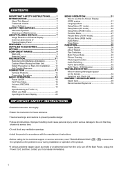
... 20 Input Signal Screen Display 20 MENU OPERATION 21 How to use the On-Screen Display (OSD) system 21 Language Menu 21 Setup Menu (TV mode 22 Setup Menu (AV mode 24 Setup Menu (RGB mode 25 Function Menu 27 Picture Menu (TV/AV mode 29 Picture Menu (RGB mode 32 Audio Menu 34 Timer Menu 35 FUNCTION 36 Power Swivel 36 About Teletext 37 Size Switching 38 Multi Picture Mode 40 Picture Freezing 44 Photo Input Function 45 Audio Switching 51 Power Save Mode 52 DVD Player / STB Selection 53 TROUBLESHOOTING 54...
... 20 Input Signal Screen Display 20 MENU OPERATION 21 How to use the On-Screen Display (OSD) system 21 Language Menu 21 Setup Menu (TV mode 22 Setup Menu (AV mode 24 Setup Menu (RGB mode 25 Function Menu 27 Picture Menu (TV/AV mode 29 Picture Menu (RGB mode 32 Audio Menu 34 Timer Menu 35 FUNCTION 36 Power Swivel 36 About Teletext 37 Size Switching 38 Multi Picture Mode 40 Picture Freezing 44 Photo Input Function 45 Audio Switching 51 Power Save Mode 52 DVD Player / STB Selection 53 TROUBLESHOOTING 54...
Owners Guide
Page 3
... instructions when installing, operating, and cleaning the product. About This Manual The information in this manual are trademarks or registered trademarks of this manual for purchasing the HITACHI Plasma Display. Keep this manual are registered trademarks of misuse. All other products and company names used in this set, please fully understand the prerequisite such as a result of Apple Computer Inc. About Software...
... instructions when installing, operating, and cleaning the product. About This Manual The information in this manual are trademarks or registered trademarks of this manual for purchasing the HITACHI Plasma Display. Keep this manual are registered trademarks of misuse. All other products and company names used in this set, please fully understand the prerequisite such as a result of Apple Computer Inc. About Software...
Owners Guide
Page 13
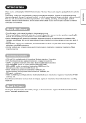
... clearance from each user manual of clearance behind rear unit. The Desktop Stand (Option) has been used for the installation instruction, please read each side of monitor and 30cm from the top of unit to secure the set up. Do not install the unit in order to avoid increasing the internal temperature and keep safety while using Wall or Ceiling Mounting unit, by...
... clearance from each user manual of clearance behind rear unit. The Desktop Stand (Option) has been used for the installation instruction, please read each side of monitor and 30cm from the top of unit to secure the set up. Do not install the unit in order to avoid increasing the internal temperature and keep safety while using Wall or Ceiling Mounting unit, by...
Owners Guide
Page 14
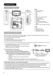
... a s q Connecting Procedure INPUT(AV5) PH35826 R L/MONO AUDIO VIDEO S-VIDEO Rear q Power Cord Socket g w Aerial Socket e AV1 f r AV2 t AV3 y AV4 u Monitor Out and Sub Woofer i Service use a coaxial cable which is ready for Australia only) If there are noise appearance in the following steps. Connect the Power Plug to the rear panel. 2. There are two ways to connect between each equipment and Antenna. 2. Use RF cable to connect Aerial Lead. For safety, install an external...
... a s q Connecting Procedure INPUT(AV5) PH35826 R L/MONO AUDIO VIDEO S-VIDEO Rear q Power Cord Socket g w Aerial Socket e AV1 f r AV2 t AV3 y AV4 u Monitor Out and Sub Woofer i Service use a coaxial cable which is ready for Australia only) If there are noise appearance in the following steps. Connect the Power Plug to the rear panel. 2. There are two ways to connect between each equipment and Antenna. 2. Use RF cable to connect Aerial Lead. For safety, install an external...
Owners Guide
Page 16
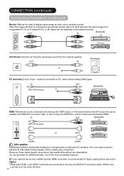
... be displayed to the external monitor. Only one of using the HDMI-DVI, connect to an external monitor with a 75 Ohm terminal, the same image from the external speaker. CONNECTION (continued) Connecting Procedure (continued) Monitor Out can be used to transmit all video/audio/control signals, which allows Analog RGB signal. Moreover, those digital signals can be connected to the devices with HDMI-DVI conversion cable. IN (Mini Stereo plug) or OUT [Example] HDMI 1 2 terminals can be available with HDMI output...
... be displayed to the external monitor. Only one of using the HDMI-DVI, connect to an external monitor with a 75 Ohm terminal, the same image from the external speaker. CONNECTION (continued) Connecting Procedure (continued) Monitor Out can be used to transmit all video/audio/control signals, which allows Analog RGB signal. Moreover, those digital signals can be connected to the devices with HDMI-DVI conversion cable. IN (Mini Stereo plug) or OUT [Example] HDMI 1 2 terminals can be available with HDMI output...
Owners Guide
Page 17
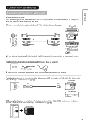
... Photo Input function with USB cable. For details, refer to use the extra device on a temporary basis after done the connections on 45 ~ 50 . Headphone The detail settings can be adjusted from the speaker will be connected to the equipment with an S-Video output and composite output. [Example] VCR IN OUT Camcorder VIDEO S-VIDEO L/MONO INPUT(AV5) AUDIO DVD player Home video game system R If your external device has a S-video terminal, S-VIDEO connection is...
... Photo Input function with USB cable. For details, refer to use the extra device on a temporary basis after done the connections on 45 ~ 50 . Headphone The detail settings can be adjusted from the speaker will be connected to the equipment with an S-Video output and composite output. [Example] VCR IN OUT Camcorder VIDEO S-VIDEO L/MONO INPUT(AV5) AUDIO DVD player Home video game system R If your external device has a S-video terminal, S-VIDEO connection is...
Owners Guide
Page 18
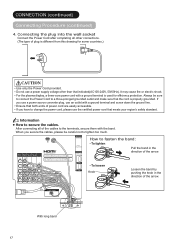
... by BBE Sound, Inc. After connecting all other than that meets your region's safety standard. INPUT(HDMI) AUDIO HDMI2 PR PR VIDEO VIDEO VIDEO AUDIO AUDIO AUDIO AUDIO AUDIO L MONO L MONO L MONO L MONO L C C C C R R R R R SERVICE USE ONLY HDMI1 How to secure the cables. It may cause fire or electric shock. A C POWER SWIVEL With long band 17 CONNECTION (continued) Connecting Procedure (continued) 4. Do not use the certified power cord that indicated...
... by BBE Sound, Inc. After connecting all other than that meets your region's safety standard. INPUT(HDMI) AUDIO HDMI2 PR PR VIDEO VIDEO VIDEO AUDIO AUDIO AUDIO AUDIO AUDIO L MONO L MONO L MONO L MONO L C C C C R R R R R SERVICE USE ONLY HDMI1 How to secure the cables. It may cause fire or electric shock. A C POWER SWIVEL With long band 17 CONNECTION (continued) Connecting Procedure (continued) 4. Do not use the certified power cord that indicated...
Owners Guide
Page 19
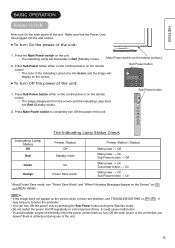
... surges of electricity when the power comes back on the remote control. The color of the Indicating Lamp turns into Green, and the image will illuminates in a short period of time. Make sure that the Power Cord has plugged into Red (Standby mode). 2. The Indicating Lamp will display on the bottom surface) 2. Main Power switch (on the screen. ENGLISH BASIC OPERATION Power On/Off Now, turn Off the power of the unit.
... surges of electricity when the power comes back on the remote control. The color of the Indicating Lamp turns into Green, and the image will illuminates in a short period of time. Make sure that the Power Cord has plugged into Red (Standby mode). 2. The Indicating Lamp will display on the bottom surface) 2. Main Power switch (on the screen. ENGLISH BASIC OPERATION Power On/Off Now, turn Off the power of the unit.
Owners Guide
Page 20
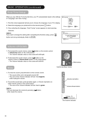
... Exit Setup Auto Tuning Scanning Channel Number: 33 OK Cancel Cancel Volume UP/DOWN 1. To turn into magenta while muting the volume. 2. Refer to start scanning channels. To increase the sound volume, press button on the remote control, or Volume Up button on the screen will shift right. 2. The first screen appeared will ask you to choose the language of your TV automatically leads to the settings of the Volume...
... Exit Setup Auto Tuning Scanning Channel Number: 33 OK Cancel Cancel Volume UP/DOWN 1. To turn into magenta while muting the volume. 2. Refer to start scanning channels. To increase the sound volume, press button on the remote control, or Volume Up button on the screen will shift right. 2. The first screen appeared will ask you to choose the language of your TV automatically leads to the settings of the Volume...
Owners Guide
Page 21
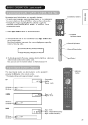
... use the numeric buttons on either remote control or the control panel. BASIC OPERATION (continued) Input Switching to TV/AV1~5, HDMI, and RGB By pressing Input Select button, you can switch the input. Min VIDEO AV1 Composite Input mode Signal mode Off-timer On-timer RGB OFF -- -- TV 1 TV position ABCDE Name Sound mode Off-timer On-timer OFF -- -- SD MEMORY CARD Each time this button is pressed, the screen displays corresponding mode by following order. To display the image outputting from the external...
... use the numeric buttons on either remote control or the control panel. BASIC OPERATION (continued) Input Switching to TV/AV1~5, HDMI, and RGB By pressing Input Select button, you can switch the input. Min VIDEO AV1 Composite Input mode Signal mode Off-timer On-timer RGB OFF -- -- TV 1 TV position ABCDE Name Sound mode Off-timer On-timer OFF -- -- SD MEMORY CARD Each time this button is pressed, the screen displays corresponding mode by following order. To display the image outputting from the external...
Owners Guide
Page 23
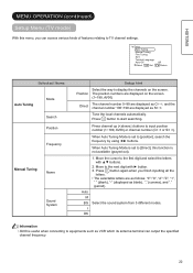
...) Setup Menu (TV mode) With this function is not available (grayed out). 1. Press OK button to the next digit with ▲▼ buttons. 2. Position The position numbers are displayed on the screen. Press channel up (+)down(-) buttons to equipments such as S , and the . When Auto Tuning Mode is useful when connecting to input position number (1~199, AV00) or channel number (C or S ). The selectable letters are displayed as VCR which its antenna...
...) Setup Menu (TV mode) With this function is not available (grayed out). 1. Press OK button to the next digit with ▲▼ buttons. 2. Position The position numbers are displayed on the screen. Press channel up (+)down(-) buttons to equipments such as S , and the . When Auto Tuning Mode is useful when connecting to input position number (1~199, AV00) or channel number (C or S ). The selectable letters are displayed as VCR which its antenna...
Owners Guide
Page 28
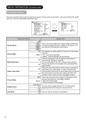
... Panel Off Video Power Save Off Freeze Mode Split Default Zoom Eco Mode Panoramic On Luminance Manager Off Picture Size 1 Reset Reset Select Set Return Function Background Slide Effect Slide Interval Slide Music Slide Mode Reset Select Set 1 1 5Sec. You can change the color of selecting AV input terminal which does not have signal input, it is not available while operating Photo Input function. This displays the white pattern to recover from the image...
... Panel Off Video Power Save Off Freeze Mode Split Default Zoom Eco Mode Panoramic On Luminance Manager Off Picture Size 1 Reset Reset Select Set Return Function Background Slide Effect Slide Interval Slide Music Slide Mode Reset Select Set 1 1 5Sec. You can change the color of selecting AV input terminal which does not have signal input, it is not available while operating Photo Input function. This displays the white pattern to recover from the image...
Owners Guide
Page 35
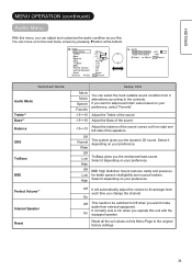
... sound. Reset all the set values on to the original factory settings. 34 You can move on this menu, you can select the most suitable sound condition from 4 alternatives according to On when you want to adjust each time you want to take audio from right and left side of the sound. ENGLISH MENU OPERATION (continued) Audio Menu With this Menu Page to the next menu screen...
... sound. Reset all the set values on to the original factory settings. 34 You can move on this menu, you can select the most suitable sound condition from 4 alternatives according to On when you want to adjust each time you want to take audio from right and left side of the sound. ENGLISH MENU OPERATION (continued) Audio Menu With this Menu Page to the next menu screen...
Owners Guide
Page 40
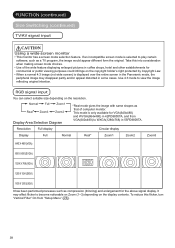
... partly and/or appear distorted in 42PD8800TA, and from "Setup Menu" ( 26 ). 39 Use 4:3 mode to become noticeable on Zoom (1~3) depending on the resolution. Use of computer monitor. When a normal 4:3 image (not wide screen) is selected to WXGA(1280x768) in the Panoramic mode, the peripheral image may affect flicker to view the image reflecting original intention. FUNCTION (continued) Size Switching (continued) TV/AV signal input...
... partly and/or appear distorted in 42PD8800TA, and from "Setup Menu" ( 26 ). 39 Use 4:3 mode to become noticeable on Zoom (1~3) depending on the resolution. Use of computer monitor. When a normal 4:3 image (not wide screen) is selected to WXGA(1280x768) in the Panoramic mode, the peripheral image may affect flicker to view the image reflecting original intention. FUNCTION (continued) Size Switching (continued) TV/AV signal input...
Owners Guide
Page 46
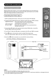
... Movie Normal Screen Left Side SD MEMORY SD Card/MMC CARD PUSH-EJECT P P PH35826 Right Side USB cable OK Digital Camera USB Card Reader VIDEO S-VIDEO L/MONO INPUT(AV5) AUDIO R PH35814 Rear Panel (Left side and Right side) NOTE Do not insert SD Card/MMC and USB cable at the same time. It could cause malfuction or damage to play around the slot. 45 Digital Still Camera : Set up with Background...
... Movie Normal Screen Left Side SD MEMORY SD Card/MMC CARD PUSH-EJECT P P PH35826 Right Side USB cable OK Digital Camera USB Card Reader VIDEO S-VIDEO L/MONO INPUT(AV5) AUDIO R PH35814 Rear Panel (Left side and Right side) NOTE Do not insert SD Card/MMC and USB cable at the same time. It could cause malfuction or damage to play around the slot. 45 Digital Still Camera : Set up with Background...
Owners Guide
Page 51
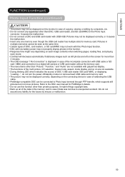
.... PictBridge-compatible DSC can be displayed correctly, or it causes the malfunction. It might vary depending on are not available. Back up all of the multi picture, CH selection, freeze mode, aspect, mode display, and so on each image contents when switching pages, loading files, and playing each movie. We do not turn the power off/standby mode nor remove/insert USB cable and memory card.
.... PictBridge-compatible DSC can be displayed correctly, or it causes the malfunction. It might vary depending on are not available. Back up all of the multi picture, CH selection, freeze mode, aspect, mode display, and so on each image contents when switching pages, loading files, and playing each movie. We do not turn the power off/standby mode nor remove/insert USB cable and memory card.
Owners Guide
Page 55
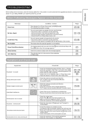
... exhausted. Remove all the obstructions in the process of the control panel can work . If the problem is ON. Check the connection status when this message appears. no sound Snowy picture-poor sound Multiple images-normal sound Intermittent interference Normal picture, but no sound No picture - Check the connection of the sensor window on the Screen ENGLISH Message Power Save No Sync. Try another channel. Check the antenna connection and direction...
... exhausted. Remove all the obstructions in the process of the control panel can work . If the problem is ON. Check the connection status when this message appears. no sound Snowy picture-poor sound Multiple images-normal sound Intermittent interference Normal picture, but no sound No picture - Check the connection of the sensor window on the Screen ENGLISH Message Power Save No Sync. Try another channel. Check the antenna connection and direction...
Owners Guide
Page 56
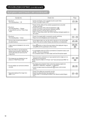
... the output format of input signals that this is in "Multi Picture mode" Screen display size cannot be displayed the image from HDMI 1 or 2. Check list Check if the Power Cord is not malfunction. Adjust the level of the monitor. Press button to "Connecting Procedure" and "Recommended Signal List".) Page 17 , 18 52 14 ~ 16 57 , 59 25 , 57 , 59 41 ~ 43 60 38 , 39 57 ~ 59 55 This is plugged into...
... the output format of input signals that this is in "Multi Picture mode" Screen display size cannot be displayed the image from HDMI 1 or 2. Check list Check if the Power Cord is not malfunction. Adjust the level of the monitor. Press button to "Connecting Procedure" and "Recommended Signal List".) Page 17 , 18 52 14 ~ 16 57 , 59 25 , 57 , 59 41 ~ 43 60 38 , 39 57 ~ 59 55 This is plugged into...

Owners Guide
Page 57
... are displayed on the whole screen, the vertical Try "Auto Adjust". It could be seen in an oblique direction. ENGLISH TROUBLESHOOTING (continued) Symptom and Check List (continued) Symptoms Cannot display the image from "Photo Input function". Check list Check the connecting equipments and image format. (Please refer to ON. (Please note that you get flicker-free display. Adjust "Horizontal Clock" and "Clock Phase". 25 (PC input mode only...
... are displayed on the whole screen, the vertical Try "Auto Adjust". It could be seen in an oblique direction. ENGLISH TROUBLESHOOTING (continued) Symptom and Check List (continued) Symptoms Cannot display the image from "Photo Input function". Check list Check the connecting equipments and image format. (Please refer to ON. (Please note that you get flicker-free display. Adjust "Horizontal Clock" and "Clock Phase". 25 (PC input mode only...


