
hp workstations - hp-ux 11.x graphics administration guide
Page 27
...Double-click on the others). single logical screen (SLS) SLS is a mechanism for every graphics device on your computer's power supply, and the power demands of the combination of graphics cards you to combine into an SLS (click the mouse on the first device, ...type. This allows the moving/spanning of windows across multiple physical monitors. The word "homogeneous" is indeed supported. configuring X Windows on HP-UX (HP Visualize graphics cards) X Server configuration multi-screen support The list of supported multi-display configurations is rather large, and it changes whenever ...
...Double-click on the others). single logical screen (SLS) SLS is a mechanism for every graphics device on your computer's power supply, and the power demands of the combination of graphics cards you to combine into an SLS (click the mouse on the first device, ...type. This allows the moving/spanning of windows across multiple physical monitors. The word "homogeneous" is indeed supported. configuring X Windows on HP-UX (HP Visualize graphics cards) X Server configuration multi-screen support The list of supported multi-display configurations is rather large, and it changes whenever ...
HP Workstations - Graphics Administration Guide For Red Hat Linux 6.2
Page 29
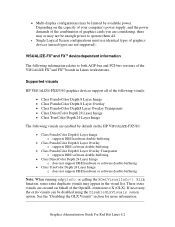
...-buffering Note: When running xdpyinfo or calling the XGetVisualInfo() Xlib function, some extra duplicate visuals may appear in Linux workstations. Supported visuals HP VISUALIZE-FXE/5/10 graphics devices support all . • Single Logical Screen configurations must use identical types of graphics devices... the visual list. These extra visuals are enabled by available power. See the "Disabling the GLX Visuals" section for more information. Depending on the capacity of your computer's power supply, and the power demands of the combination of graphics cards you are considering, ...
...-buffering Note: When running xdpyinfo or calling the XGetVisualInfo() Xlib function, some extra duplicate visuals may appear in Linux workstations. Supported visuals HP VISUALIZE-FXE/5/10 graphics devices support all . • Single Logical Screen configurations must use identical types of graphics devices... the visual list. These extra visuals are enabled by available power. See the "Disabling the GLX Visuals" section for more information. Depending on the capacity of your computer's power supply, and the power demands of the combination of graphics cards you are considering, ...

hp workstations - hp-ux 10.20 graphics administration guide
Page 45
...next section). The word "homogeneous" is introduced. There are considering a Single Logical Screen or any other multidisplay configuration, we recommend consulting your computer's power supply, and the power demands of the combination of graphics cards you have in the SLS Configuration are of the same type. Page 45 Graphics Administration Guide for..., and it changes whenever a new graphics device is included because SLS only works if the graphics devices included in mind is a mechanism for HP-UX 10.20 This allows the moving/spanning of windows across multiple physical monitors.
...next section). The word "homogeneous" is introduced. There are considering a Single Logical Screen or any other multidisplay configuration, we recommend consulting your computer's power supply, and the power demands of the combination of graphics cards you have in the SLS Configuration are of the same type. Page 45 Graphics Administration Guide for..., and it changes whenever a new graphics device is included because SLS only works if the graphics devices included in mind is a mechanism for HP-UX 10.20 This allows the moving/spanning of windows across multiple physical monitors.

hp workstation J6700 service handbook
Page 5
...Bootable Media 111 Resetting the Workstation 112 Displaying and Setting Paths 113 Displaying and Setting the Monitor Type 115 The Monitor Command 115 Displaying the Current Monitor Configuration 116 Setting the Monitor Type 116 Setting the Monitor Type at Power On 118 Troubleshooting Monitor ... Accessing the Boot Console Handler 104 Boot Console Menus 105 Booting the Workstation 109 Searching for All Removal and Replacement Procedures . . .85 Front Bezel and Top Cover 86 Internal CD ROM Drive 91 Power Supply 92 PCI Cage 94 Speaker 95 Removing the System Board 96 Replacing...
...Bootable Media 111 Resetting the Workstation 112 Displaying and Setting Paths 113 Displaying and Setting the Monitor Type 115 The Monitor Command 115 Displaying the Current Monitor Configuration 116 Setting the Monitor Type 116 Setting the Monitor Type at Power On 118 Troubleshooting Monitor ... Accessing the Boot Console Handler 104 Boot Console Menus 105 Booting the Workstation 109 Searching for All Removal and Replacement Procedures . . .85 Front Bezel and Top Cover 86 Internal CD ROM Drive 91 Power Supply 92 PCI Cage 94 Speaker 95 Removing the System Board 96 Replacing...

hp workstation J6700 service handbook
Page 10
It has a 715 Watt power supply with no DC/DC converter units required. Net Dimensions and Weights The dimensions for the deskside system are listed below. • Depth: 25.8 inches (65...main sections: • Product Description • Front Panel Components • Rear Panel Components • Internal Components • Monitors • Keyboard and Mouse Product Description The HP VISUALIZE J6700 workstation is a high-performance system capable of handling the most complex problems in computational analysis, advanced 3-D design, and electronic circuit design and verification.
It has a 715 Watt power supply with no DC/DC converter units required. Net Dimensions and Weights The dimensions for the deskside system are listed below. • Depth: 25.8 inches (65...main sections: • Product Description • Front Panel Components • Rear Panel Components • Internal Components • Monitors • Keyboard and Mouse Product Description The HP VISUALIZE J6700 workstation is a high-performance system capable of handling the most complex problems in computational analysis, advanced 3-D design, and electronic circuit design and verification.

hp workstation J6700 service handbook
Page 12
...aggregate I/O bandwidth - Up to 16GB total) • Power Supply: - 500 Watt (output power), 715 Watt (input power) with two VRM modules • Remote Power-On - Two USB (Universal Serial Bus) connectors (keyboard... System (Native HP-UX): - 64-bit support requires HP-UX version 11.0 plus ACE 1199 and HP-UX version 11i plus ACE 0601. • User Interface: HP CDE (Common... 1GB up and shut down your workstation remotely through the RS232 port. • Internal Storage Devices: - Product Information Product Description Key Features The J6700 workstations have the following key features. &#...
...aggregate I/O bandwidth - Up to 16GB total) • Power Supply: - 500 Watt (output power), 715 Watt (input power) with two VRM modules • Remote Power-On - Two USB (Universal Serial Bus) connectors (keyboard... System (Native HP-UX): - 64-bit support requires HP-UX version 11.0 plus ACE 1199 and HP-UX version 11i plus ACE 0601. • User Interface: HP CDE (Common... 1GB up and shut down your workstation remotely through the RS232 port. • Internal Storage Devices: - Product Information Product Description Key Features The J6700 workstations have the following key features. &#...

hp workstation J6700 service handbook
Page 28
.... Product Information Internal Components Microprocessors The J6700 has two PA-8700 microprocessors with the most recent designs in active Power Factor Correction (PFC) power supplies such as those in the HP J6700 workstations. Each microprocessor is independent of 750MHz. The maximum power needed by a "turbocooler" which provide I/O expansion capabilities for the workstation. The power supply weighs approximately 8 lbs. (4 kg.). Please note...
.... Product Information Internal Components Microprocessors The J6700 has two PA-8700 microprocessors with the most recent designs in active Power Factor Correction (PFC) power supplies such as those in the HP J6700 workstations. Each microprocessor is independent of 750MHz. The maximum power needed by a "turbocooler" which provide I/O expansion capabilities for the workstation. The power supply weighs approximately 8 lbs. (4 kg.). Please note...

hp workstation J6700 service handbook
Page 72
... by the System Controller. white dot is 0.1 second LED is working correctly. The LED blink sequences are correctly plugged in. Note that the power supply cables are shown in the system. The default state for this light is on , indicates that the voltage regulator module is off . for .... A potential fix may be to check that each blink of the LED represents a tenth of this does not work, call you local HP Support Representative. If this light. Interpreting the System Board LEDs LED Name LED's Color Description When On VRM0 Green FETCH FANS Green Yellow (blinking)...
... by the System Controller. white dot is 0.1 second LED is working correctly. The LED blink sequences are correctly plugged in. Note that the power supply cables are shown in the system. The default state for this light is on , indicates that the voltage regulator module is off . for .... A potential fix may be to check that each blink of the LED represents a tenth of this does not work, call you local HP Support Representative. If this light. Interpreting the System Board LEDs LED Name LED's Color Description When On VRM0 Green FETCH FANS Green Yellow (blinking)...

hp workstation J6700 service handbook
Page 75
... Check that no pieces of the FANS LED, the LED is blinking sequence 1, 2, or 6 or it is bad, replace it to replace the power supply. Chapter 3 75 If power supply fans are bad, you must replace the system board. If the PCI fan is not blinking. The LEDs are bad, you have failed. If... state, or in the case of metal are bent and touching each other 1. Blink Sequence 6 Check that the 24-pin power supply signal cable is properly connected Press the power button off and unplug the system and wait for two minutes before turning the system back on SHORT ON If the following...
... Check that no pieces of the FANS LED, the LED is blinking sequence 1, 2, or 6 or it is bad, replace it to replace the power supply. Chapter 3 75 If power supply fans are bad, you must replace the system board. If the PCI fan is not blinking. The LEDs are bad, you have failed. If... state, or in the case of metal are bent and touching each other 1. Blink Sequence 6 Check that the 24-pin power supply signal cable is properly connected Press the power button off and unplug the system and wait for two minutes before turning the system back on SHORT ON If the following...

hp workstation J6700 service handbook
Page 78
... and Top Panel - LCD Panel - PCI Backplane - The exceptions to power off the workstation and unplug the workstation power cord from the AC power outlet. Hard disk Drive Backplane - Power Supply - PCI Cage - System Board - For these you only need to this chapter, you must power off the workstation. Exploded View Diagram - Real-Time Clock WARNING For most of...
... and Top Panel - LCD Panel - PCI Backplane - The exceptions to power off the workstation and unplug the workstation power cord from the AC power outlet. Hard disk Drive Backplane - Power Supply - PCI Cage - System Board - For these you only need to this chapter, you must power off the workstation. Exploded View Diagram - Real-Time Clock WARNING For most of...

hp workstation J6700 service handbook
Page 81
...-69032 Description J6700 System Board Assembly Power supply 500W includes system speaker, power supply fans, and LCD display cable 512 MB SDRAM DIMM 1 GB SDRAM DIMM LVD Ultra SCSI hard disk 18 GB 10K RPM LVD Ultra SCSI hard disk 36 GB 10K RPM Chapter 4 81 J6700 Exchange Part Numbers Numbers in exchange for the J6700 workstation. you...
...-69032 Description J6700 System Board Assembly Power supply 500W includes system speaker, power supply fans, and LCD display cable 512 MB SDRAM DIMM 1 GB SDRAM DIMM LVD Ultra SCSI hard disk 18 GB 10K RPM LVD Ultra SCSI hard disk 36 GB 10K RPM Chapter 4 81 J6700 Exchange Part Numbers Numbers in exchange for the J6700 workstation. you...

hp workstation J6700 service handbook
Page 82
...Mounts CD ROM drive to chassis, system board mounting, PCI backplane mounting, and power supply mounting) Jackscrew - 4 - 40Mx4F M3 screws for the J6700 workstation. bezel bottom (blank - no branding) J6700 Rack Mount Kit2 Rack mounting hardware kit2 Cable management assembly Front bezel end caps ...Right side cover (with logo)3 Left side cover (with J6700 branding) Trim - Table 4-2. Field Replaceable ...
...Mounts CD ROM drive to chassis, system board mounting, PCI backplane mounting, and power supply mounting) Jackscrew - 4 - 40Mx4F M3 screws for the J6700 workstation. bezel bottom (blank - no branding) J6700 Rack Mount Kit2 Rack mounting hardware kit2 Cable management assembly Front bezel end caps ...Right side cover (with logo)3 Left side cover (with J6700 branding) Trim - Table 4-2. Field Replaceable ...

hp workstation J6700 service handbook
Page 92
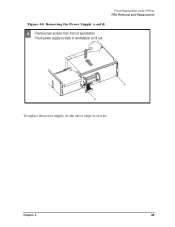
Removing the Power Supply 1 - Remove two VRM connectors - Remove screw from back of workstation to remove power plug - Remove VRM 1 board as shown VRM 0 VRM connector VRM 1 VRM connector 2 - Field Replaceable Units (FRUs) FRU Removal and Replacement Power Supply To remove the power supply, do the following: Figure 4-7. Disconnect five connectors (2-6) power plug 1 Back 1 screw 5 6 3 2 Power Supply 4 92 Chapter 4
Removing the Power Supply 1 - Remove two VRM connectors - Remove screw from back of workstation to remove power plug - Remove VRM 1 board as shown VRM 0 VRM connector VRM 1 VRM connector 2 - Field Replaceable Units (FRUs) FRU Removal and Replacement Power Supply To remove the power supply, do the following: Figure 4-7. Disconnect five connectors (2-6) power plug 1 Back 1 screw 5 6 3 2 Power Supply 4 92 Chapter 4
hp workstation J6700 service handbook
Page 93
Chapter 4 93 To replace the power supply, do the above steps in reverse. Push power supply to back of workstation - Field Replaceable Units (FRUs) FRU Removal and Replacement Figure 4-8. Removing the Power Supply (cont'd) 4 - Remove two screws from front of workstation to lift out.
Chapter 4 93 To replace the power supply, do the above steps in reverse. Push power supply to back of workstation - Field Replaceable Units (FRUs) FRU Removal and Replacement Figure 4-8. Removing the Power Supply (cont'd) 4 - Remove two screws from front of workstation to lift out.

hp workstation J6700 service handbook
Page 95
Disconnect fan power plug 2. Slide board to back of cage and lift out To replace the PCI Backplane and Cage, do the above steps in reverse. If the speaker fails, replace the power supply. Removing the PCI Backplane 1 1. Remove mounting screw 1 Fan power plug Field Replaceable Units (FRUs) FRU Removal and Replacement 2 PCI mounting screw 2 - Speaker The speaker is integrated into the power supply. Chapter 4 95 Figure 4-10.
Disconnect fan power plug 2. Slide board to back of cage and lift out To replace the PCI Backplane and Cage, do the above steps in reverse. If the speaker fails, replace the power supply. Removing the PCI Backplane 1 1. Remove mounting screw 1 Fan power plug Field Replaceable Units (FRUs) FRU Removal and Replacement 2 PCI mounting screw 2 - Speaker The speaker is integrated into the power supply. Chapter 4 95 Figure 4-10.

hp workstation J6700 technical reference manual
Page 12
...: 3.4 inches (8.6 cm) 12 Chapter 1 The J6700 has two PA-8700 microprocessors and sixteen memory slots on its system board. It has a 715 Watt power supply with no DC/DC converter units required. Product Information... Chapter Overview Chapter Overview This chapter contains the following main sections: • Product Description • Front Panel Components • Rear Panel Components • Internal Components • Monitors • Keyboard and Mouse Product Description The HP VISUALIZE J6700 workstation...
...: 3.4 inches (8.6 cm) 12 Chapter 1 The J6700 has two PA-8700 microprocessors and sixteen memory slots on its system board. It has a 715 Watt power supply with no DC/DC converter units required. Product Information... Chapter Overview Chapter Overview This chapter contains the following main sections: • Product Description • Front Panel Components • Rear Panel Components • Internal Components • Monitors • Keyboard and Mouse Product Description The HP VISUALIZE J6700 workstation...

hp workstation J6700 technical reference manual
Page 14
...cache and 1.5 MB data cache. • Operating System (Native HP-UX): - 64-bit support requires HP-UX version 11.0 plus ACE 1199 or the HP-UX version 11i plus ACE 0601 • User Interface: HP CDE (Common Desktop Environment) graphical user interface • Compatibility:...GB DIMMs - Product Information Product Description Key Features The J6700 workstations have the following key features. • CPUs: - Up to 16GB total) • Power Supply: - 500 Watt (output power), 715 Watt (input power) with two VRM modules • Remote Power-On - One Low-Voltage Differential (LVD)/Single-ended (...
...cache and 1.5 MB data cache. • Operating System (Native HP-UX): - 64-bit support requires HP-UX version 11.0 plus ACE 1199 or the HP-UX version 11i plus ACE 0601 • User Interface: HP CDE (Common Desktop Environment) graphical user interface • Compatibility:...GB DIMMs - Product Information Product Description Key Features The J6700 workstations have the following key features. • CPUs: - Up to 16GB total) • Power Supply: - 500 Watt (output power), 715 Watt (input power) with two VRM modules • Remote Power-On - One Low-Voltage Differential (LVD)/Single-ended (...

hp workstation J6700 technical reference manual
Page 30
...most recent designs in active Power Factor Correction (PFC) power supplies such as those in the power supply. Each processor has 0.75 MB instruction cache and a 1.5 MB data cache. Each microprocessor is cooled by a fully-configured SPU is located in the HP J6700 workstations. The hard disk drives are... three PCI-4X, 64 bit, 3.3v, 66 MHz slots which consists of the power supply. The output is 52A. 30 Chapter 1 Power Supply The power system is located in the Hard Disk Drive section. ...
...most recent designs in active Power Factor Correction (PFC) power supplies such as those in the power supply. Each processor has 0.75 MB instruction cache and a 1.5 MB data cache. Each microprocessor is cooled by a fully-configured SPU is located in the HP J6700 workstations. The hard disk drives are... three PCI-4X, 64 bit, 3.3v, 66 MHz slots which consists of the power supply. The output is 52A. 30 Chapter 1 Power Supply The power system is located in the Hard Disk Drive section. ...

hp workstation J6700 technical reference manual
Page 70
... this light. Note that one or both processors is working correctly. If the FANS LED is on , indicates that the power supply cables are correctly plugged in. A potential fix may be to check that the voltage regulator module is fetching code. ... are six LED blink sequences supported by the system controller at power up. 3 q q q q q q q q q q r r r r r r r r r r System controller's transient state. Troubleshooting Using the System Board LEDs for this does not work, call you local HP Support Representative. The default state for Troubleshooting Table 2-2. This system...
... this light. Note that one or both processors is working correctly. If the FANS LED is on , indicates that the power supply cables are correctly plugged in. A potential fix may be to check that the voltage regulator module is fetching code. ... are six LED blink sequences supported by the system controller at power up. 3 q q q q q q q q q q r r r r r r r r r r System controller's transient state. Troubleshooting Using the System Board LEDs for this does not work, call you local HP Support Representative. The default state for Troubleshooting Table 2-2. This system...

hp workstation J6700 technical reference manual
Page 73
... system back on SHORT ON If the following solutions do not bring the LED back on system connectors are bent and touching each other 1. If power supply fans are in the OFF state, or in the case of the FANS LED, the LED is blinking sequence 1, 2, or 6 or it is bad, replace... it to replace the power supply. Solutions for the Non-Default LED States LED Name1 Non-Default Solution State FANS OFF or blink sequence 4, 5 or 6 If the following solutions do not...
... system back on SHORT ON If the following solutions do not bring the LED back on system connectors are bent and touching each other 1. If power supply fans are in the OFF state, or in the case of the FANS LED, the LED is blinking sequence 1, 2, or 6 or it is bad, replace... it to replace the power supply. Solutions for the Non-Default LED States LED Name1 Non-Default Solution State FANS OFF or blink sequence 4, 5 or 6 If the following solutions do not...


