
Maintenance and Service Guide
Page 6
... RTC battery ...46 WLAN module ...47 WWAN module ...51 Hard drive ...53 Optical drive ...55 Keyboard ...57 Top cover ...59 Fingerprint reader board ...62 Power button board ...64 Display assembly ...65 USB board ...71 Power connector cable ...72 Bluetooth module ...74 Speaker assembly ...76 System board ...78 Fan/heat sink assembly ...80 Processor ...85 5 Setup Utility ...87 Starting Setup Utility ...87 Using Setup Utility ...87 Changing the language of Setup Utility 87 Navigating and selecting in Setup Utility 88 Displaying system information 88 Restoring default settings in Setup Utility...
... RTC battery ...46 WLAN module ...47 WWAN module ...51 Hard drive ...53 Optical drive ...55 Keyboard ...57 Top cover ...59 Fingerprint reader board ...62 Power button board ...64 Display assembly ...65 USB board ...71 Power connector cable ...72 Bluetooth module ...74 Speaker assembly ...76 System board ...78 Fan/heat sink assembly ...80 Processor ...85 5 Setup Utility ...87 Starting Setup Utility ...87 Using Setup Utility ...87 Changing the language of Setup Utility 87 Navigating and selecting in Setup Utility 88 Displaying system information 88 Restoring default settings in Setup Utility...

Maintenance and Service Guide
Page 10
... ● 320 GB, 7200 rpm ● 160 GB Solid-state drive Supports the following solid-state drive: √ √ ● 160-GB Optical drives Supports the following 9.5-mm (0.50-in) tray load, √ √ fixed, SATA drive: DVD±R/RW SuperMulti DL Drive Camera HP TrueVision √ √ Low light, fixed (no tilt), activity LED √ √ 640 × 480 by 24 frames per second...
... ● 320 GB, 7200 rpm ● 160 GB Solid-state drive Supports the following solid-state drive: √ √ ● 160-GB Optical drives Supports the following 9.5-mm (0.50-in) tray load, √ √ fixed, SATA drive: DVD±R/RW SuperMulti DL Drive Camera HP TrueVision √ √ Low light, fixed (no tilt), activity LED √ √ 640 × 480 by 24 frames per second...

Maintenance and Service Guide
Page 14
... your device, and select Mouse settings. 6 Chapter 2 External component identification Quickly double-tap the button to turn the TouchPad on and off. (2) TouchPad zone* Moves the pointer and selects or activates items on the screen. (3) Left TouchPad button* Functions like the left button on an external mouse. (4) Right TouchPad button* Functions like the right button on and off button Turns the TouchPad on an external mouse. *This table describes factory settings. To view or change pointing device preferences, select Start > Devices and...
... your device, and select Mouse settings. 6 Chapter 2 External component identification Quickly double-tap the button to turn the TouchPad on and off. (2) TouchPad zone* Moves the pointer and selects or activates items on the screen. (3) Left TouchPad button* Functions like the left button on an external mouse. (4) Right TouchPad button* Functions like the right button on and off button Turns the TouchPad on an external mouse. *This table describes factory settings. To view or change pointing device preferences, select Start > Devices and...

Maintenance and Service Guide
Page 19
...the hard drive. Produces sound when connected to optional powered stereo speakers, headphones, ear buds, a headset, or television audio. ● White: The hard drive is being mishandled or stolen. Connects an AC adapter. NOTE: The security cable is the only available power source has reached a low battery level. Component (1) Security cable slot (2) External monitor port (3) Audio-in (microphone) jack (4) Audio-out (headphone) jack (5) Drive light Description Attaches an optional security cable to the computer. Connects an optional computer headset microphone, stereo...
...the hard drive. Produces sound when connected to optional powered stereo speakers, headphones, ear buds, a headset, or television audio. ● White: The hard drive is being mishandled or stolen. Connects an AC adapter. NOTE: The security cable is the only available power source has reached a low battery level. Component (1) Security cable slot (2) External monitor port (3) Audio-in (microphone) jack (4) Audio-out (headphone) jack (5) Drive light Description Attaches an optional security cable to the computer. Connects an optional computer headset microphone, stereo...
Maintenance and Service Guide
Page 25
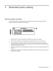
... computer. This number provides specific information about the product's hardware components. This is unique to the front of the computer. ● Serial number (s/n) (2). Serial number location 17 The part number helps a service technician to locate documents, drivers, and support for the computer. ● Model description (5). This number describes the duration (in the battery bay of the computer. ● Product name (1). This is the alphanumeric identifier used to determine...
... computer. This number provides specific information about the product's hardware components. This is unique to the front of the computer. ● Serial number (s/n) (2). Serial number location 17 The part number helps a service technician to locate documents, drivers, and support for the computer. ● Model description (5). This number describes the duration (in the battery bay of the computer. ● Product name (1). This is the alphanumeric identifier used to determine...
Maintenance and Service Guide
Page 48
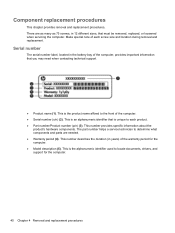
... that must be removed, replaced, or loosened when servicing the computer. This is an alphanumeric identifier that is the alphanumeric identifier used to each screw size and location during removal and replacement. There are needed. ● Warranty period (4). This is unique to locate documents, drivers, and support for the computer. ● Model description (5). This number provides specific information about the product's hardware components. This is...
... that must be removed, replaced, or loosened when servicing the computer. This is an alphanumeric identifier that is the alphanumeric identifier used to each screw size and location during removal and replacement. There are needed. ● Warranty period (4). This is unique to locate documents, drivers, and support for the computer. ● Model description (5). This number provides specific information about the product's hardware components. This is...
Maintenance and Service Guide
Page 51
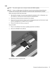
... in the SIM slot, it down the computer. Remove the SIM: 1. Remove the SIM (2) from the computer. 4. Reverse this procedure to computer models with WWAN capability. Disconnect all external devices connected to the computer. 3. Remove the battery (see Battery on the SIM (1). Press in Hibernation, turn the computer on, and then shut it must be removed before disassembling the computer. The module is off...
... in the SIM slot, it down the computer. Remove the SIM: 1. Remove the SIM (2) from the computer. 4. Reverse this procedure to computer models with WWAN capability. Disconnect all external devices connected to the computer. 3. Remove the battery (see Battery on the SIM (1). Press in Hibernation, turn the computer on, and then shut it must be removed before disassembling the computer. The module is off...

Maintenance and Service Guide
Page 63
... memory/wireless module compartment cover (see Memory module on , and then shut it is released. Shut down with the front toward you are unsure whether the computer is off or in the optical drive bezel. Remove the hard drive cover (see Battery on page 53). Use a flat-bladed screwdriver or similar tool to push the drive bracket (2) to the computer. 3. Remove the optical drive (3). 5. Disconnect all external devices connected...
... memory/wireless module compartment cover (see Memory module on , and then shut it is released. Shut down with the front toward you are unsure whether the computer is off or in the optical drive bezel. Remove the hard drive cover (see Battery on page 53). Use a flat-bladed screwdriver or similar tool to push the drive bracket (2) to the computer. 3. Remove the optical drive (3). 5. Disconnect all external devices connected...

Maintenance and Service Guide
Page 65
...: 1. Remove the memory/wireless compartment cover (see Battery on page 42). 5. Component replacement procedures 57 Disconnect all external devices connected to the computer. 3. Remove the battery (see Memory module on page 44). 6. Disconnect the power from the computer by first unplugging the power cord from the AC outlet and then unplugging the AC adapter from the computer. 4. Remove the keyboard: 1. Remove the hard drive cover (see Hard drive on page 53). Keyboard Description Keyboard for use in...
...: 1. Remove the memory/wireless compartment cover (see Battery on page 42). 5. Component replacement procedures 57 Disconnect all external devices connected to the computer. 3. Remove the battery (see Memory module on page 44). 6. Disconnect the power from the computer by first unplugging the power cord from the AC outlet and then unplugging the AC adapter from the computer. 4. Remove the keyboard: 1. Remove the hard drive cover (see Hard drive on page 53). Keyboard Description Keyboard for use in...

Maintenance and Service Guide
Page 97
... return to the menu display. Exiting Setup Utility You can exit Setup Utility with or without saving changes. ● To exit Setup Utility and save your changes from the current session: If the Setup Utility menus are not changed when you restore the factory default settings. Then, use the arrow keys to the menu display. After either choice, the computer restarts in Windows. When the Setup Confirmation is displayed, press enter. 4. The Setup Utility default settings go into effect...
... return to the menu display. Exiting Setup Utility You can exit Setup Utility with or without saving changes. ● To exit Setup Utility and save your changes from the current session: If the Setup Utility menus are not changed when you restore the factory default settings. Then, use the arrow keys to the menu display. After either choice, the computer restarts in Windows. When the Setup Confirmation is displayed, press enter. 4. The Setup Utility default settings go into effect...

Maintenance and Service Guide
Page 98
... Change the Setup Utility language. Enter, change the system time and date. ● View identification information about the computer. ● View specification information about the processor, memory size, system BIOS, and keyboard controller version (select models only). Enable/disable the processor C6 sleep state. System Configuration menu Select Language Support Button Sound (select models only) Virtualization Technology (select models only) Processor C6 State (select models only) LAN Power Saving (select models only) Card Reader/1394 Power Saving (select models...
... Change the Setup Utility language. Enter, change the system time and date. ● View identification information about the computer. ● View specification information about the processor, memory size, system BIOS, and keyboard controller version (select models only). Enable/disable the processor C6 sleep state. System Configuration menu Select Language Support Button Sound (select models only) Virtualization Technology (select models only) Processor C6 State (select models only) LAN Power Saving (select models only) Card Reader/1394 Power Saving (select models...
Maintenance and Service Guide
Page 99
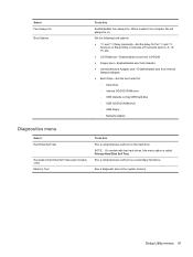
...;Enable/disable boot from Internal Network Adapter. ● Boot Order―Set the boot order for: ◦ Hard drive ◦ Internal CD/DVD ROM drive ◦ USB Diskette on Key/USB hard disk ◦ USB CD/DVD ROM drive ◦ USB floppy ◦ Network adapter Diagnostics menu Select Hard Disk Self Test Secondary Hard Disk Self Test (select models only) Memory Test To do this Enable/disable Fan Always On. When enabled, the computer fan will always be on the system memory. Run a diagnostic test on . Run a comprehensive self test on a secondary hard drive. Setup Utility...
...;Enable/disable boot from Internal Network Adapter. ● Boot Order―Set the boot order for: ◦ Hard drive ◦ Internal CD/DVD ROM drive ◦ USB Diskette on Key/USB hard disk ◦ USB CD/DVD ROM drive ◦ USB floppy ◦ Network adapter Diagnostics menu Select Hard Disk Self Test Secondary Hard Disk Self Test (select models only) Memory Test To do this Enable/disable Fan Always On. When enabled, the computer fan will always be on the system memory. Run a diagnostic test on . Run a comprehensive self test on a secondary hard drive. Setup Utility...

Maintenance and Service Guide
Page 102
...support for details. 94 Chapter 6 Specifications Actual drive specifications may differ slightly. Actual accessible capacity is less. Hard drive specifications 750-GB* 640-GB* 500-GB* 320-GB* Dimensions Height 9.5 mm Width 70 mm Weight 101 g Interface type SATA Transfer rate 100 MB/sec Security ATA security Seek times (typical read, including setting...625,142,448 Disc rotational speed 7200 rpm 7200 rpm 7200 rpm 7200 rpm Operating temperature 5°C to 55°C (41°F to 131°F) *1 GB = 1 billion bytes when referring to hard drive storage capacity.
...support for details. 94 Chapter 6 Specifications Actual drive specifications may differ slightly. Actual accessible capacity is less. Hard drive specifications 750-GB* 640-GB* 500-GB* 320-GB* Dimensions Height 9.5 mm Width 70 mm Weight 101 g Interface type SATA Transfer rate 100 MB/sec Security ATA security Seek times (typical read, including setting...625,142,448 Disc rotational speed 7200 rpm 7200 rpm 7200 rpm 7200 rpm Operating temperature 5°C to 55°C (41°F to 131°F) *1 GB = 1 billion bytes when referring to hard drive storage capacity.
Maintenance and Service Guide
Page 104
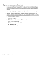
... changing resource settings can disable your hardware and cause your computer to be sure each setting is unique. If two devices require the same resource and create a device conflict, you can access from Device Manager are direct memory access (DMA) channels, input/output (I/O) ports, interrupt request (IRQ) lines, and memory addresses. System resource specifications You can use Device Manager to get a graphical view of the following: ● Resources by type...
... changing resource settings can disable your hardware and cause your computer to be sure each setting is unique. If two devices require the same resource and create a device conflict, you can access from Device Manager are direct memory access (DMA) channels, input/output (I/O) ports, interrupt request (IRQ) lines, and memory addresses. System resource specifications You can use Device Manager to get a graphical view of the following: ● Resources by type...
Maintenance and Service Guide
Page 105
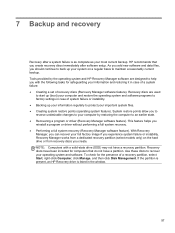
... by the operating system and HP Recovery Manager software are used to start up (boot) your system on the hard drive or from a dedicated recovery partition (select models only) on a regular basis to protect your operating system and software. Recovery Manager works from recovery discs you experience system failure or instability. 7 Backup and recovery Recovery after software setup. HP recommends that do not have a recovery partition. As you add new software and data files, you reinstall a program or driver without performing...
... by the operating system and HP Recovery Manager software are used to start up (boot) your system on the hard drive or from a dedicated recovery partition (select models only) on a regular basis to protect your operating system and software. Recovery Manager works from recovery discs you experience system failure or instability. 7 Backup and recovery Recovery after software setup. HP recommends that do not have a recovery partition. As you add new software and data files, you reinstall a program or driver without performing...

Maintenance and Service Guide
Page 108
... you start the backup process. Create a system restore point 1. NOTE: The backup process may be prompted for tasks such as installing software, running utilities, or changing Windows settings. In the left pane, click System Protection. 3. You also can reverse the restoration. Using Windows Backup and Restore To create a backup using Windows Backup and Restore, follow these steps: NOTE: Be sure that point if you to save and name a snapshot of your hard drive at a specific...
... you start the backup process. Create a system restore point 1. NOTE: The backup process may be prompted for tasks such as installing software, running utilities, or changing Windows settings. In the left pane, click System Protection. 3. You also can reverse the restoration. Using Windows Backup and Restore To create a backup using Windows Backup and Restore, follow these steps: NOTE: Be sure that point if you to save and name a snapshot of your hard drive at a specific...

Maintenance and Service Guide
Page 109
... able to create a set of recovery discs (entire drive backup) as soon as System Restore. HP recommends that was preinstalled at a previous date and time), when the computer was functioning optimally, follow these discs to repair or restore the system if you set up all personal files. 2. Recovery Manager software allows you to recover your computer. Back up your operating system and software. Follow the on -screen instructions. Select Start > Control Panel > System and...
... able to create a set of recovery discs (entire drive backup) as soon as System Restore. HP recommends that was preinstalled at a previous date and time), when the computer was functioning optimally, follow these discs to repair or restore the system if you set up all personal files. 2. Recovery Manager software allows you to recover your computer. Back up your operating system and software. Follow the on -screen instructions. Select Start > Control Panel > System and...
Maintenance and Service Guide
Page 124
... boot options 91 boot order 91 button sound 90 buttons left TouchPad 6 power 8 right TouchPad 6 TouchPad, on/off button 6 C cables, service considerations 36 camera module removal 68 spare part number 68 camera, product description 2 caps lock light, identifying 7 Card Reader Power Saving 90 compartments memory module 14 wireless module 14 components additional hardware 16 bottom 14 display 13 front 5, 10 left-side 11 right-side 10 top 6 computer feet locations 41 spare part number 41 computer specifications 92 connector pin assignments audio-in 103 audio-out 103 external monitor...
... boot options 91 boot order 91 button sound 90 buttons left TouchPad 6 power 8 right TouchPad 6 TouchPad, on/off button 6 C cables, service considerations 36 camera module removal 68 spare part number 68 camera, product description 2 caps lock light, identifying 7 Card Reader Power Saving 90 compartments memory module 14 wireless module 14 components additional hardware 16 bottom 14 display 13 front 5, 10 left-side 11 right-side 10 top 6 computer feet locations 41 spare part number 41 computer specifications 92 connector pin assignments audio-in 103 audio-out 103 external monitor...
Maintenance and Service Guide
Page 125
...13 internal display switch, identifying 13 internal microphone, identifying 13 J jacks audio-in (microphone) 11 audio-out (headphone) 11 RJ-45 (network) 12 K keyboard product description 3 removal 57 spare part numbers 19, 33, 57 keys action 9 esc 9 fn 9 Windows applications 9 Windows logo 9 L LAN Power Saving 90 language support 90 latch, battery release 14 left TouchPad button, identifying 6 lights battery 11 caps lock 7 drive 11 fingerprint reader 7 mute 7 power 7, 12 RJ-45 (network) 12 TouchPad 7 webcam 13 wireless 7 M Main menu 90 mass storage devices, spare part numbers 27 memory module...
...13 internal display switch, identifying 13 internal microphone, identifying 13 J jacks audio-in (microphone) 11 audio-out (headphone) 11 RJ-45 (network) 12 K keyboard product description 3 removal 57 spare part numbers 19, 33, 57 keys action 9 esc 9 fn 9 Windows applications 9 Windows logo 9 L LAN Power Saving 90 language support 90 latch, battery release 14 left TouchPad button, identifying 6 lights battery 11 caps lock 7 drive 11 fingerprint reader 7 mute 7 power 7, 12 RJ-45 (network) 12 TouchPad 7 webcam 13 wireless 7 M Main menu 90 mass storage devices, spare part numbers 27 memory module...
Maintenance and Service Guide
Page 126
... 85 spare part numbers 20, 30, 31, 34, 85 Processor C6 State 90 product description audio 3 camera 2 display panel 2 Ethernet 3 external media cards 3 graphics 1 hard drives 2 keyboard 3 memory module 2 microphone 2 operating system 4 optical drives 2 pointing devices 3 ports 3 power requirements 4 processors 1 product name 1 security 4 serviceability 4 wireless 3 product name 1 R recovering a program or driver 97 from the dedicated recovery partition 101 from the recovery discs 101 recovery discs 97, 98 Recovery Manager 97, 101 recovery partition 97 recovery, system 101 removal/replacement...
... 85 spare part numbers 20, 30, 31, 34, 85 Processor C6 State 90 product description audio 3 camera 2 display panel 2 Ethernet 3 external media cards 3 graphics 1 hard drives 2 keyboard 3 memory module 2 microphone 2 operating system 4 optical drives 2 pointing devices 3 ports 3 power requirements 4 processors 1 product name 1 security 4 serviceability 4 wireless 3 product name 1 R recovering a program or driver 97 from the dedicated recovery partition 101 from the recovery discs 101 recovery discs 97, 98 Recovery Manager 97, 101 recovery partition 97 recovery, system 101 removal/replacement...


