
Service Manual
Page 9
The purpose of this appendix is to provide supplemental service information that is unique to the HP LaserJet 5P and 5MP printers. 2 These processes are documented in common with their predecessors, the HP LaserJet 4L/4ML and 4P/4MP printers. HP LaserJet 5P Printer Service Supplement Overview Overview The HP LaserJet 5P and 5MP printers (HP Product Numbers C3150A and C3155A) have many service and repair processes in the Combined Service Manual for the HP LaserJet 4L/4ML (C2003A/C2015A) HP LaserJet 4P/4MP (C2005A/C2040A).
The purpose of this appendix is to provide supplemental service information that is unique to the HP LaserJet 5P and 5MP printers. 2 These processes are documented in common with their predecessors, the HP LaserJet 4L/4ML and 4P/4MP printers. HP LaserJet 5P Printer Service Supplement Overview Overview The HP LaserJet 5P and 5MP printers (HP Product Numbers C3150A and C3155A) have many service and repair processes in the Combined Service Manual for the HP LaserJet 4L/4ML (C2003A/C2015A) HP LaserJet 4P/4MP (C2005A/C2040A).

Service Manual
Page 45
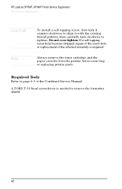
Required Tools Refer to remove the formatter shield. 38 A TORX T-10 head screwdriver is needed to page 6-3 of the Combined Service Manual. HP LaserJet 5P Printer Service Supplement Removal and Replacement Note Always remove the toner cartridge and the paper cassette from the printer before removing or replacing printer parts.
Required Tools Refer to remove the formatter shield. 38 A TORX T-10 head screwdriver is needed to page 6-3 of the Combined Service Manual. HP LaserJet 5P Printer Service Supplement Removal and Replacement Note Always remove the toner cartridge and the paper cassette from the printer before removing or replacing printer parts.
Service Manual
Page 59
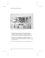
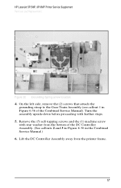
... bottom of the DC Controller Assembly. (See callouts 2 and 3 in Figure 6-36 in Figure 6-36 of the Combined Service Manual). Remove the (5) self-tapping screws and the (1) machine screw with further steps. 5. HP LaserJet 5P Printer Service Supplement Removal and Replacement Figure 25 Grounding Spring screw location. 4. On the left side, remove the (2) screws that attach...
... bottom of the DC Controller Assembly. (See callouts 2 and 3 in Figure 6-36 in Figure 6-36 of the Combined Service Manual). Remove the (5) self-tapping screws and the (1) machine screw with further steps. 5. HP LaserJet 5P Printer Service Supplement Removal and Replacement Figure 25 Grounding Spring screw location. 4. On the left side, remove the (2) screws that attach...
Service Manual
Page 60
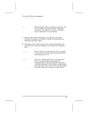
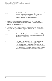
...can easily be broken when separating it from the DC Controller Assembly (see pages 6-43 and 6-44 in the Combined Service Manual for this procedure.) 8. HP LaserJet 5P Printer Service Supplement Removal and Replacement Note The PS1 Input Sensor Arm may come loose and fall out when you remove the DC...plate from the black plastic cover. Disconnect Tray 1 Interconnect PCA (callout 2 in Figure 26) and cable 302 (callout 1 in the Combined Service Manual for the DC Controller Board does not include a replacement PCA and cable. See Figure 6-51 in Figure 26) from the connector no releases...
...can easily be broken when separating it from the DC Controller Assembly (see pages 6-43 and 6-44 in the Combined Service Manual for this procedure.) 8. HP LaserJet 5P Printer Service Supplement Removal and Replacement Note The PS1 Input Sensor Arm may come loose and fall out when you remove the DC...plate from the black plastic cover. Disconnect Tray 1 Interconnect PCA (callout 2 in Figure 26) and cable 302 (callout 1 in the Combined Service Manual for the DC Controller Board does not include a replacement PCA and cable. See Figure 6-51 in Figure 26) from the connector no releases...
Service Manual
Page 67
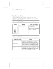
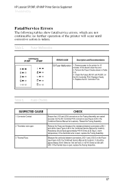
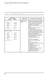
...Service Manual for location). Connector Contact 2. Thermistor wire open. 3. Remove the Fuser and measure the resistance between connectors J103-1 and J103-2 on the DC Controller PCA. Fuser Malfunction LED Display ERROR CODE 50 Fuser Malfunction Description and Recommendation 1. Reseat the Fusing Assembly. Thermal Fuse. HP LaserJet 5P Printer Service Supplement Troubleshooting Fatal/Service... Errors The following tables show fatal/service errors, which are seated...
...Service Manual for location). Connector Contact 2. Thermistor wire open. 3. Remove the Fuser and measure the resistance between connectors J103-1 and J103-2 on the DC Controller PCA. Fuser Malfunction LED Display ERROR CODE 50 Fuser Malfunction Description and Recommendation 1. Reseat the Fusing Assembly. Thermal Fuse. HP LaserJet 5P Printer Service Supplement Troubleshooting Fatal/Service... Errors The following tables show fatal/service errors, which are seated...
Service Manual
Page 68
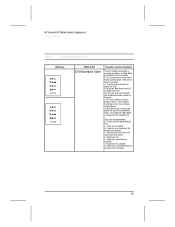
Power-cycle the printer. Check the fan to "Drum Rotation Functional Check in the Combined Service Manual. Reseat the fan connector on power-up the printer and observe if stacker rollers rotate. f. Replace the DC Controller. Power-cycle ...that would block the free operation of the gears. Main Motor faulty. If the main motor does rotate: 2. If no : a. c. d. e. d. HP LaserJet 5P Printer Service Supplement Troubleshooting Table 7. 57/58 Main Motor Failure LED Display ERROR CODE 57/58 Main Motor Failure Description and Recommendation The DC Controller has reported...
Power-cycle the printer. Check the fan to "Drum Rotation Functional Check in the Combined Service Manual. Reseat the fan connector on power-up the printer and observe if stacker rollers rotate. f. Replace the DC Controller. Power-cycle ...that would block the free operation of the gears. Main Motor faulty. If the main motor does rotate: 2. If no : a. c. d. e. d. HP LaserJet 5P Printer Service Supplement Troubleshooting Table 7. 57/58 Main Motor Failure LED Display ERROR CODE 57/58 Main Motor Failure Description and Recommendation The DC Controller has reported...
Service Manual
Page 98
HP C3150A Printer Service Manual Reader's Comment Sheet Please give us create better manuals in making our manuals more useful and friendly. March 1995 5010-6305 Your constructive criticism will help us your response. I you for your feedback. Thank you would like a reply, be sure to include your name and address with your comments concerning this manual. Be as specific as possible, giving section and page reference where appropriate. Comments on the writing, graphics, binding, size, and printing method are helpful in the future.
HP C3150A Printer Service Manual Reader's Comment Sheet Please give us create better manuals in making our manuals more useful and friendly. March 1995 5010-6305 Your constructive criticism will help us your response. I you for your feedback. Thank you would like a reply, be sure to include your name and address with your comments concerning this manual. Be as specific as possible, giving section and page reference where appropriate. Comments on the writing, graphics, binding, size, and printing method are helpful in the future.

Service Manual
Page 104
The purpose of this appendix is to provide supplemental service information that is unique to the HP LaserJet 5P/5MP and 6P/6MP printers. Overview The HP LaserJet 5P/5MP and 6P/6MP printers (HP Product Numbers C3150A/C3155A, and C3980A/C3982A) have many service and repair processes in the Combined Service Manual for the HP LaserJet 4L/4ML (C2003A/C2015A) HP LaserJet 4P/4MP (C2005A/C2040A). These processes are documented in common with their predecessors, the HP LaserJet 4L/4ML and 4P/4MP printers.
The purpose of this appendix is to provide supplemental service information that is unique to the HP LaserJet 5P/5MP and 6P/6MP printers. Overview The HP LaserJet 5P/5MP and 6P/6MP printers (HP Product Numbers C3150A/C3155A, and C3980A/C3982A) have many service and repair processes in the Combined Service Manual for the HP LaserJet 4L/4ML (C2003A/C2015A) HP LaserJet 4P/4MP (C2005A/C2040A). These processes are documented in common with their predecessors, the HP LaserJet 4L/4ML and 4P/4MP printers.
Service Manual
Page 145
HP LaserJet 5P/5MP, 6P/6MP Printer Service Supplement Removal and Replacement CAUTION Note To install a self-tapping screw, first turn it counter-clockwise to align it with the existing thread pattern, then ... Tools Refer to tighten. Do not over-tighten. If a self-tapping screw-hole becomes stripped, repair of the screw-hole or replacement of the Combined Service Manual. A TORX T-10 head screwdriver is required.
HP LaserJet 5P/5MP, 6P/6MP Printer Service Supplement Removal and Replacement CAUTION Note To install a self-tapping screw, first turn it counter-clockwise to align it with the existing thread pattern, then ... Tools Refer to tighten. Do not over-tighten. If a self-tapping screw-hole becomes stripped, repair of the screw-hole or replacement of the Combined Service Manual. A TORX T-10 head screwdriver is required.
Service Manual
Page 160
HP LaserJet 5P/5MP, 6P/6MP Printer Service Supplement Removal and Replacement Figure 28 Grounding Spring screw location. 4. On the left side, remove the (2) screws that attach the grounding strap to the Gear Train Assembly (see callout 1 in Figure 6-36 of the DC Controller Assembly. (See callouts 2 and 3 in Figure 6-36 in the Combined Service Manual....) 6. Remove the (5) self-tapping screws and the (1) machine screw with further steps. 5. Lift the DC Controller Assembly away from the bottom of the Combined Service Manual). Turn the assembly upside-...
HP LaserJet 5P/5MP, 6P/6MP Printer Service Supplement Removal and Replacement Figure 28 Grounding Spring screw location. 4. On the left side, remove the (2) screws that attach the grounding strap to the Gear Train Assembly (see callout 1 in Figure 6-36 of the DC Controller Assembly. (See callouts 2 and 3 in Figure 6-36 in the Combined Service Manual....) 6. Remove the (5) self-tapping screws and the (1) machine screw with further steps. 5. Lift the DC Controller Assembly away from the bottom of the Combined Service Manual). Turn the assembly upside-...
Service Manual
Page 161
...Service Manual for this procedure.) 8. Caution Remove the Tray 1 Interconnect PCA carefully; This cable can easily be broken when separating it from the connector no releases are necessary. 58 Note The Tray 1 Interconnect PCA and cable must also be directly pulled from the black plastic cover. The part number for re-installation. 7. HP LaserJet 5P.../5MP, 6P/6MP Printer Service Supplement Removal and Replacement Note The PS1 Input Sensor Arm may come loose and fall out ...
...Service Manual for this procedure.) 8. Caution Remove the Tray 1 Interconnect PCA carefully; This cable can easily be broken when separating it from the connector no releases are necessary. 58 Note The Tray 1 Interconnect PCA and cable must also be directly pulled from the black plastic cover. The part number for re-installation. 7. HP LaserJet 5P.../5MP, 6P/6MP Printer Service Supplement Removal and Replacement Note The PS1 Input Sensor Arm may come loose and fall out ...
Service Manual
Page 170
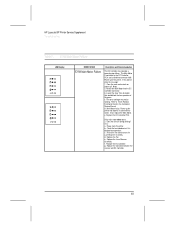
...continuity between connectors J204-1 and J204-2 (see Figure 6-29 in the Combined Service Manual for location). Check the Fuses (FU101 and FU201) on the Fuser (see Figure 6-29, the Combined Service Manual for location). Table 6. Thermistor wire open , replace the Fusing Assembly. ... 50 Fuser Malfunction 1. HP LaserJet 5P/5MP, 6P/6MP Printer Service Supplement Troubleshooting Fatal/Service Errors The following tables show fatal/service errors, which are seated securely into the DC Controller PCA connectors (see Figure 6-29 in the Combined Service Manual for locations). no further...
...continuity between connectors J204-1 and J204-2 (see Figure 6-29 in the Combined Service Manual for location). Check the Fuses (FU101 and FU201) on the Fuser (see Figure 6-29, the Combined Service Manual for location). Table 6. Thermistor wire open , replace the Fusing Assembly. ... 50 Fuser Malfunction 1. HP LaserJet 5P/5MP, 6P/6MP Printer Service Supplement Troubleshooting Fatal/Service Errors The following tables show fatal/service errors, which are seated securely into the DC Controller PCA connectors (see Figure 6-29 in the Combined Service Manual for locations). no further...
Service Manual
Page 171
...and seated into the DC Controller connector. Power-cycle the printer. Check the fan to "Drum Rotation Functional Check in the Combined Service Manual. d. g. The Main Motor is blocked from operation. Does the main motor rotate on the Laser/Scanner Assembly. The toner ... Replace the Fan. Does the fan turn during printing? Replace the Laser/Scanner Assembly. HP LaserJet 5P/5MP, 6P/6MP Printer Service Supplement Troubleshooting Table 7. 57/58 Main Motor Failure LED Display 5P/5MP 6P/6MP ERROR CODE 57/58 Main Motor Failure Description and Recommendation The DC Controller...
...and seated into the DC Controller connector. Power-cycle the printer. Check the fan to "Drum Rotation Functional Check in the Combined Service Manual. d. g. The Main Motor is blocked from operation. Does the main motor rotate on the Laser/Scanner Assembly. The toner ... Replace the Fan. Does the fan turn during printing? Replace the Laser/Scanner Assembly. HP LaserJet 5P/5MP, 6P/6MP Printer Service Supplement Troubleshooting Table 7. 57/58 Main Motor Failure LED Display 5P/5MP 6P/6MP ERROR CODE 57/58 Main Motor Failure Description and Recommendation The DC Controller...

Supplement
Page 8
The purpose of this appendix is to provide supplemental service information that is unique to the HP LaserJet 5P and 5MP printers. 2 HP LaserJet 5P Printer Service Supplement Overview Overview The HP LaserJet 5P and 5MP printers (HP Product Numbers C3150A and C3155A) have many service and repair processes in the Combined Service Manual for the HP LaserJet 4L/4ML (C2003A/C2015A) HP LaserJet 4P/4MP (C2005A/C2040A). These processes are documented in common with their predecessors, the HP LaserJet 4L/4ML and 4P/4MP printers.
The purpose of this appendix is to provide supplemental service information that is unique to the HP LaserJet 5P and 5MP printers. 2 HP LaserJet 5P Printer Service Supplement Overview Overview The HP LaserJet 5P and 5MP printers (HP Product Numbers C3150A and C3155A) have many service and repair processes in the Combined Service Manual for the HP LaserJet 4L/4ML (C2003A/C2015A) HP LaserJet 4P/4MP (C2005A/C2040A). These processes are documented in common with their predecessors, the HP LaserJet 4L/4ML and 4P/4MP printers.

Supplement
Page 44
Required Tools Refer to remove the formatter shield. 38 A TORX T-10 head screwdriver is needed to page 6-3 of the Combined Service Manual. HP LaserJet 5P Printer Service Supplement Removal and Replacement Note Always remove the toner cartridge and the paper cassette from the printer before removing or replacing printer parts.
Required Tools Refer to remove the formatter shield. 38 A TORX T-10 head screwdriver is needed to page 6-3 of the Combined Service Manual. HP LaserJet 5P Printer Service Supplement Removal and Replacement Note Always remove the toner cartridge and the paper cassette from the printer before removing or replacing printer parts.

Supplement
Page 58
... in Figure 6-36 of the Combined Service Manual). Turn the assembly upside-down before proceeding with star washer from the printer frame. 52 On the left side, remove the (2) screws that attach the grounding strap to the Gear Train Assembly (see callout 1 in the Combined Service Manual.) 6. HP LaserJet 5P Printer Service Supplement Removal and Replacement Figure 25...
... in Figure 6-36 of the Combined Service Manual). Turn the assembly upside-down before proceeding with star washer from the printer frame. 52 On the left side, remove the (2) screws that attach the grounding strap to the Gear Train Assembly (see callout 1 in the Combined Service Manual.) 6. HP LaserJet 5P Printer Service Supplement Removal and Replacement Figure 25...

Supplement
Page 59
HP LaserJet 5P Printer Service Supplement Removal and Replacement Note The PS1 Input Sensor Arm may come loose and fall out when you remove the DC Controller Assembly. Remove the ... can easily be retained when replacing the DC Controller Board. Disconnect Tray 1 Interconnect PCA (callout 2 in Figure 26) and cable 302 (callout 1 in the Combined Service Manual for the DC Controller Board does not include a replacement PCA and cable. Caution Remove the Tray 1 Interconnect PCA carefully; The part number for re-installation...
HP LaserJet 5P Printer Service Supplement Removal and Replacement Note The PS1 Input Sensor Arm may come loose and fall out when you remove the DC Controller Assembly. Remove the ... can easily be retained when replacing the DC Controller Board. Disconnect Tray 1 Interconnect PCA (callout 2 in Figure 26) and cable 302 (callout 1 in the Combined Service Manual for the DC Controller Board does not include a replacement PCA and cable. Caution Remove the Tray 1 Interconnect PCA carefully; The part number for re-installation...

Supplement
Page 66
...(room temperature). Table 6. Measure the continuity between connectors J204-1 and J204-2 (see Figure 6-29 in the Combined Service Manual for 220-245 VAC. Reseat the Fusing Assembly. Fuser Malfunction LED Display ERROR CODE 50 Fuser Malfunction Description and Recommendation... Remove power to the printer for locations). HP LaserJet 5P Printer Service Supplement Troubleshooting Fatal/Service Errors The following tables show fatal/service errors, which are seated securely into the DC Controller PCA connectors (see Figure 6-29 in the Combined Service Manual for 10 minutes.
...(room temperature). Table 6. Measure the continuity between connectors J204-1 and J204-2 (see Figure 6-29 in the Combined Service Manual for 220-245 VAC. Reseat the Fusing Assembly. Fuser Malfunction LED Display ERROR CODE 50 Fuser Malfunction Description and Recommendation... Remove power to the printer for locations). HP LaserJet 5P Printer Service Supplement Troubleshooting Fatal/Service Errors The following tables show fatal/service errors, which are seated securely into the DC Controller PCA connectors (see Figure 6-29 in the Combined Service Manual for 10 minutes.
Supplement
Page 67
b. The toner cartridge may not be rotating. e. If the main motor does rotate: 2. b. HP LaserJet 5P Printer Service Supplement Troubleshooting Table 7. 57/58 Main Motor Failure LED Display ERROR CODE 57/58 Main Motor Failure Description and Recommendation The DC ...this doesn't clear the message: 1. If no : a. Does the fan turn during printing? Check the fan to "Drum Rotation Functional Check in the Combined Service Manual. Reseat the fan connector on power-up the printer and observe if stacker rollers rotate. The Main Motor is blocked from operation. e. Reseat the Main...
b. The toner cartridge may not be rotating. e. If the main motor does rotate: 2. b. HP LaserJet 5P Printer Service Supplement Troubleshooting Table 7. 57/58 Main Motor Failure LED Display ERROR CODE 57/58 Main Motor Failure Description and Recommendation The DC ...this doesn't clear the message: 1. If no : a. Does the fan turn during printing? Check the fan to "Drum Rotation Functional Check in the Combined Service Manual. Reseat the fan connector on power-up the printer and observe if stacker rollers rotate. The Main Motor is blocked from operation. e. Reseat the Main...

Supplement
Page 97
Comments on the writing, graphics, binding, size, and printing method are helpful in the future. March 1995 5010-6305 I you for your feedback. Be as specific as possible, giving section and page reference where appropriate. HP C3150A Printer Service Manual Reader's Comment Sheet Please give us create better manuals in making our manuals more useful and friendly. Your constructive criticism will help us your response. Thank you would like a reply, be sure to include your name and address with your comments concerning this manual.
Comments on the writing, graphics, binding, size, and printing method are helpful in the future. March 1995 5010-6305 I you for your feedback. Be as specific as possible, giving section and page reference where appropriate. HP C3150A Printer Service Manual Reader's Comment Sheet Please give us create better manuals in making our manuals more useful and friendly. Your constructive criticism will help us your response. Thank you would like a reply, be sure to include your name and address with your comments concerning this manual.


