
User Manual
Page 5
... Source 2-21 iii Prepare the Installation Site 2-7 Cabling Infrastructure 2-7 Installation Location 2-8 2. Install the Grounding Wire 2-21 7. Install Switch Modules 2-9 3. (Optional) Install Another Power Supply 2-12 4. Contents 1 Introducing the ProCurve Series 5400zl Switches Front of the Switch 1-5 LEDs 1-6 LED Mode Select Button and Indicator LEDs 1-9 Console Port 1-10 Reset Button 1-10 Clear Button 1-10 Back...
... Source 2-21 iii Prepare the Installation Site 2-7 Cabling Infrastructure 2-7 Installation Location 2-8 2. Install the Grounding Wire 2-21 7. Install Switch Modules 2-9 3. (Optional) Install Another Power Supply 2-12 4. Contents 1 Introducing the ProCurve Series 5400zl Switches Front of the Switch 1-5 LEDs 1-6 LED Mode Select Button and Indicator LEDs 1-9 Console Port 1-10 Reset Button 1-10 Clear Button 1-10 Back...

User Manual
Page 6
... Access 2-27 Telnet Console Access 2-27 Hot Swapping Switch Modules 2-28 Adding or Replacing Modules 2-28 Changing the Module Type 2-28 Example Network Topologies 2-29 Basic Connectivity 2-29 Use as an Edge Switch 2-30 3 Getting Started With Switch Configuration Recommended Minimal Configuration 3-1 Using the Switch Setup Screen 3-2 Where to the switch 2-22 EPS Operation 2-22 Operating Characteristics of...
... Access 2-27 Telnet Console Access 2-27 Hot Swapping Switch Modules 2-28 Adding or Replacing Modules 2-28 Changing the Module Type 2-28 Example Network Topologies 2-29 Basic Connectivity 2-29 Use as an Edge Switch 2-30 3 Getting Started With Switch Configuration Recommended Minimal Configuration 3-1 Using the Switch Setup Screen 3-2 Where to the switch 2-22 EPS Operation 2-22 Operating Characteristics of...
User Manual
Page 11
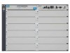
..., the Switch 5406zxl-48G and Switch 5412zl-96G. The Switch 5406zl is available as an open 6-slot chassis (J8697A) does not ship with two 24-port 10/100/1000-T zl Modules pre-installed. This chapter describes your Series 5400zl Switches including: ■ Front and back of the switches ■ Features ■ Switch operation overview Switch 5406zl, Switch 5406zl-48G...
..., the Switch 5406zxl-48G and Switch 5412zl-96G. The Switch 5406zl is available as an open 6-slot chassis (J8697A) does not ship with two 24-port 10/100/1000-T zl Modules pre-installed. This chapter describes your Series 5400zl Switches including: ■ Front and back of the switches ■ Features ■ Switch operation overview Switch 5406zl, Switch 5406zl-48G...

User Manual
Page 12
Figure 1-2. ProCurve Switch 5406zl-48G bundle (J8699A) with one power supply, the J8712A. Introducing the ProCurve Series 5400zl Switches Introducing the ProCurve Series 5400zl Switches Note The 5406zl-48G bundle (J8699A) does ship with two 10/100/1000-T zl Modules 1-2
Figure 1-2. ProCurve Switch 5406zl-48G bundle (J8699A) with one power supply, the J8712A. Introducing the ProCurve Series 5400zl Switches Introducing the ProCurve Series 5400zl Switches Note The 5406zl-48G bundle (J8699A) does ship with two 10/100/1000-T zl Modules 1-2

User Manual
Page 14
ProCurve Switch 5412zl-96G (J8700A) See "Switch Features" on page 1-13 for a list of the switch modules that can be installed in the ProCurve Series 5400zl Switches (modules available when this manual was printed). 1-4 Introducing the ProCurve Series 5400zl Switches Note The 5412zl-96G bundle (J8700A) ships with two power supplies, the J8712A. Introducing the ProCurve Series 5400zl Switches Figure 1-4.
ProCurve Switch 5412zl-96G (J8700A) See "Switch Features" on page 1-13 for a list of the switch modules that can be installed in the ProCurve Series 5400zl Switches (modules available when this manual was printed). 1-4 Introducing the ProCurve Series 5400zl Switches Note The 5412zl-96G bundle (J8700A) ships with two power supplies, the J8712A. Introducing the ProCurve Series 5400zl Switches Figure 1-4.

User Manual
Page 15
... and descriptions apply to all of the Switch Power and Fault LEDs Locator LED Status LEDs for the Fans, Power Supplies, and Switch Modules Reset and Clear buttons LED Mode Select button and indicator LEDs Auxiliary Port Console Port Module Link and Mode LEDs Self Test LED Switch Modules and slots with Link and Mode LEDs...
... and descriptions apply to all of the Switch Power and Fault LEDs Locator LED Status LEDs for the Fans, Power Supplies, and Switch Modules Reset and Clear buttons LED Mode Select button and indicator LEDs Auxiliary Port Console Port Module Link and Mode LEDs Self Test LED Switch Modules and slots with Link and Mode LEDs...

User Manual
Page 16
... On On briefly at the beginning of switch self test after you informed of the status of the switch and the network connections. See chapter 4, "Troubleshooting" for future releases. Reserved for example a switch module, and the switch Fault LED will flash simultaneously. On DIMM.... Table 1-1. Introducing the ProCurve Series 5400zl Switches Introducing the ProCurve Series 5400zl Switches Front of the Switch LEDs As described in progress after the switch is unresolved. The Self Test LED also comes on the switch, one of the switch modules, an individual port, a power supply, ...
... On On briefly at the beginning of switch self test after you informed of the status of the switch and the network connections. See chapter 4, "Troubleshooting" for future releases. Reserved for example a switch module, and the switch Fault LED will flash simultaneously. On DIMM.... Table 1-1. Introducing the ProCurve Series 5400zl Switches Introducing the ProCurve Series 5400zl Switches Front of the Switch LEDs As described in progress after the switch is unresolved. The Self Test LED also comes on the switch, one of the switch modules, an individual port, a power supply, ...

User Manual
Page 17
...is a fault on ("hot swap"). A power supply is not installed in the back of the Switch LEDs State Meaning Mgmt (green/Orange) On A Management module is not installed in the switch module slot corresponding to an active AC power source, or has experienced a fault. Off No External Power... Supply is powered off. A module is present and fault free. On letters corresponding to the switch module slots) Off Blinking1 A module is undergoing or has passed self test. If the LED flashes for a more of the ...
...is a fault on ("hot swap"). A power supply is not installed in the back of the Switch LEDs State Meaning Mgmt (green/Orange) On A Management module is not installed in the switch module slot corresponding to an active AC power source, or has experienced a fault. Off No External Power... Supply is powered off. A module is present and fault free. On letters corresponding to the switch module slots) Off Blinking1 A module is undergoing or has passed self test. If the LED flashes for a more of the ...

User Manual
Page 18
...an on /off cycle once every 0.5 seconds, approximately. The switch Fault, Self Test LEDs, and appropriate module status LEDs will flash simultaneously. Introducing the ProCurve Series 5400zl Switches Introducing the ProCurve Series 5400zl Switches Front of these conditions exists: • no active network ... is enabled for PoE. • If the Link LED is off cycle once every 1.6 seconds, approximately. 1-8 Table 1-2. Switch Module LEDs These LEDs are displaying the connection speed at 1000 Mbps Usr Reserved for future development Auxiliary (green/ Orange) Reserved for the...
...an on /off cycle once every 0.5 seconds, approximately. The switch Fault, Self Test LEDs, and appropriate module status LEDs will flash simultaneously. Introducing the ProCurve Series 5400zl Switches Introducing the ProCurve Series 5400zl Switches Front of these conditions exists: • no active network ... is enabled for PoE. • If the Link LED is off cycle once every 1.6 seconds, approximately. 1-8 Table 1-2. Switch Module LEDs These LEDs are displaying the connection speed at 1000 Mbps Usr Reserved for future development Auxiliary (green/ Orange) Reserved for the...

User Manual
Page 20
...can be reset to the Switch" in any of the switch module slots while the switch is not being supplied on a standard VT-100 terminal. This action clears any switch console access passwords that is installed in the switch console interface, the switch web browser interface, and through...secure location, such as ProCurve Manager. The counters are concerned with the switch. In this port. • Fast Blinking = This port is provided for the following purposes: ■ Deleting Passwords - See "Hot Swapping Switch Modules" on . This button is denied PoE power or has an external...
...can be reset to the Switch" in any of the switch module slots while the switch is not being supplied on a standard VT-100 terminal. This action clears any switch console access passwords that is installed in the switch console interface, the switch web browser interface, and through...secure location, such as ProCurve Manager. The counters are concerned with the switch. In this port. • Fast Blinking = This port is provided for the following purposes: ■ Deleting Passwords - See "Hot Swapping Switch Modules" on . This button is denied PoE power or has an external...
User Manual
Page 27
...) is properly prepared including having the correct network cabling ready to connect to install your switch. Install switch modules (page 2-9). The Switch 5406zl-48G has two 24-port 10/1001000-T zl Modules preinstalled and the 5412zl-96G has four 24-port 10/1001000-T zl Modules preinstalled. Make sure you will be reinstalled. 2-3 Installing the Series 5400zl...
...) is properly prepared including having the correct network cabling ready to connect to install your switch. Install switch modules (page 2-9). The Switch 5406zl-48G has two 24-port 10/1001000-T zl Modules preinstalled and the 5412zl-96G has four 24-port 10/1001000-T zl Modules preinstalled. Make sure you will be reinstalled. 2-3 Installing the Series 5400zl...

User Manual
Page 33
... the instructions in the illustration below. Retain the slot cover for safe operation and proper switch cooling. Installing the Series 5400zl Switches Caution Module Installation Notes Installing the Series 5400zl Switches Installation Procedures 2. See "Hot Swapping the Switch Module" on the module is contacting the front face of the slots, ensure the slot cover plate is installed...
... the instructions in the illustration below. Retain the slot cover for safe operation and proper switch cooling. Installing the Series 5400zl Switches Caution Module Installation Notes Installing the Series 5400zl Switches Installation Procedures 2. See "Hot Swapping the Switch Module" on the module is contacting the front face of the slots, ensure the slot cover plate is installed...

User Manual
Page 39
...different power cord than the one supplied with the switch, please see the "Installation Precautions" on each of the switch modules. Check the LEDs on the switch and on page 2-6. 2. Refer to a power source. Installing the Series 5400zl Switches Note Figure 2-5. Power Connector on when the power... cord is connected to the switch and to chapter 4, "Troubleshooting" for...
...different power cord than the one supplied with the switch, please see the "Installation Precautions" on each of the switch modules. Check the LEDs on the switch and on page 2-6. 2. Refer to a power source. Installing the Series 5400zl Switches Note Figure 2-5. Power Connector on when the power... cord is connected to the switch and to chapter 4, "Troubleshooting" for...

User Manual
Page 40
...and the Status LEDs on the switch chassis stay on for the devices installed: one for each switch module installed, one for each power supply installed, and one for a fully loaded chassis, depending on . Switch Fault, Module, and Chassis LEDs When the switch is completed, the module LEDs go off . ■...; The port LEDs on the switch modules go on as the port is tested. ■ For the duration of the self...
...and the Status LEDs on the switch chassis stay on for the devices installed: one for each switch module installed, one for each power supply installed, and one for a fully loaded chassis, depending on . Switch Fault, Module, and Chassis LEDs When the switch is completed, the module LEDs go off . ■...; The port LEDs on the switch modules go on as the port is tested. ■ For the duration of the self...

User Manual
Page 49
... configured an IP address on the connected device. for information on the types of switch modules you have used the correct cable type for troubleshooting procedures. Installing the Series 5400zl Switches Installing the Series 5400zl Switches Installation Procedures 9. See appendix B, "Switch Ports and Network Cables" for fiber-optic connections, verify the transmit port on the...
... configured an IP address on the connected device. for information on the types of switch modules you have used the correct cable type for troubleshooting procedures. Installing the Series 5400zl Switches Installing the Series 5400zl Switches Installation Procedures 9. See appendix B, "Switch Ports and Network Cables" for fiber-optic connections, verify the transmit port on the...

User Manual
Page 52
... to flash. 2-28 Until the switch is rebooted, the module will not operate and the Module Status LED for the affected slot will continue to the switch operation. Installing the Series 5400zl Switches Installing the Series 5400zl Switches Hot Swapping Switch Modules Hot Swapping Switch Modules The switch modules can be "hot swapped" (except for the Management Module, it is not hot swappable...
... to flash. 2-28 Until the switch is rebooted, the module will not operate and the Module Status LED for the affected slot will continue to the switch operation. Installing the Series 5400zl Switches Installing the Series 5400zl Switches Hot Swapping Switch Modules Hot Swapping Switch Modules The switch modules can be "hot swapped" (except for the Management Module, it is not hot swappable...

User Manual
Page 72
... LEDs Table 5-1 shows LED patterns on the next few pages. Refer to the corresponding diagnostic tip on the switch and the switch modules that indicate problem conditions. 1. Table 5-1. Troubleshooting Power Fault Test Module Status (one LED per module) Power (one LED per power supply) Fan Port Link Troubleshooting Diagnosing with the LEDs Diagnosing with cable...
... LEDs Table 5-1 shows LED patterns on the next few pages. Refer to the corresponding diagnostic tip on the switch and the switch modules that indicate problem conditions. 1. Table 5-1. Troubleshooting Power Fault Test Module Status (one LED per module) Power (one LED per power supply) Fan Port Link Troubleshooting Diagnosing with the LEDs Diagnosing with cable...

User Manual
Page 113
... ... 2-26 managing the switch ... 3-1 included parts ... 2-1 installation connecting the switch to a power source ... 2-21 horizontal surface mounting ... 2-20 network cable requirements ... 2-7 optional modules ... 2-9 precautions ... 2-5, 2-6 rack or cabinet mounting ... 2-17 redundant power supply ... 2-12 Series 5400zl Switches ... 2-1 site preparation ... 2-7 summary of steps ... 2-3 IP address configuring ... 3-3 using for new module type ... 2-28 switch modules ... 2-28 HP Auto-MDIX feature description...
... ... 2-26 managing the switch ... 3-1 included parts ... 2-1 installation connecting the switch to a power source ... 2-21 horizontal surface mounting ... 2-20 network cable requirements ... 2-7 optional modules ... 2-9 precautions ... 2-5, 2-6 rack or cabinet mounting ... 2-17 redundant power supply ... 2-12 Series 5400zl Switches ... 2-1 site preparation ... 2-7 summary of steps ... 2-3 IP address configuring ... 3-3 using for new module type ... 2-28 switch modules ... 2-28 HP Auto-MDIX feature description...

User Manual
Page 114
B-6 required types ... 2-7 twisted-pair connector pin-outs ... B-3 HP Auto-MDIX feature ... B-6 twisted-pair, specifications ... B-7 network devices connecting to the switch ... 2-25 network ports connecting to MDI-X network cable ... Index N network cables ...topologies, examples of ... 2-29 non-standard network cables, effects ... 5-2 O out-of available types ... 1-13 mounting the switch in a rack or cabinet ... 2-17 precautions ... 2-5, 2-6 on switch modules ... 1-8 Power ... 1-6 behavior during error conditions ... 5-4 behavior during self test ... 2-16 Power Status ... 1-7 behavior...
B-6 required types ... 2-7 twisted-pair connector pin-outs ... B-3 HP Auto-MDIX feature ... B-6 twisted-pair, specifications ... B-7 network devices connecting to the switch ... 2-25 network ports connecting to MDI-X network cable ... Index N network cables ...topologies, examples of ... 2-29 non-standard network cables, effects ... 5-2 O out-of available types ... 1-13 mounting the switch in a rack or cabinet ... 2-17 precautions ... 2-5, 2-6 on switch modules ... 1-8 Power ... 1-6 behavior during error conditions ... 5-4 behavior during self test ... 2-16 Power Status ... 1-7 behavior...

User Manual
Page 116
...rack or cabinet ... 2-17 mounting on a horizontal surface ... 2-20 physical specifications ... A-1 switch chassis LED descriptions ... 1-6 switch modules booting the switch to initialize changed module type ... 2-9 hot swapping ... 2-28 installing ... 2-9 LEDs descriptions ... 1-8 list of non...11 switch operation ... 5-10 switch-to -switch or hub connection ... A-1 environmental specifications ... Index B-9 testing ... 5-11 twisted-pair ports HP Auto-MDIX feature ... B-8, B-10 switch-to a power source ... 2-21 description ... 1-1 electrical specifications ... Index switch connecting...
...rack or cabinet ... 2-17 mounting on a horizontal surface ... 2-20 physical specifications ... A-1 switch chassis LED descriptions ... 1-6 switch modules booting the switch to initialize changed module type ... 2-9 hot swapping ... 2-28 installing ... 2-9 LEDs descriptions ... 1-8 list of non...11 switch operation ... 5-10 switch-to -switch or hub connection ... A-1 environmental specifications ... Index B-9 testing ... 5-11 twisted-pair ports HP Auto-MDIX feature ... B-8, B-10 switch-to a power source ... 2-21 description ... 1-1 electrical specifications ... Index switch connecting...


