User Manual
Page 7
... Basic Troubleshooting Tips 5-1 Diagnosing with the LEDs 5-4 Proactive Networking 5-9 Hardware Diagnostic Tests 5-10 Testing the Switch by Resetting It 5-10 Checking the Switch LEDs 5-10 Checking Console Messages 5-10 Testing Twisted-Pair Cabling 5-11 Testing Switch-to-Device Network Communications 5-11 Testing End-to-End Network Communications 5-11 Restoring the Factory Default Configuration 5-12 Downloading New Code 5-13 HP Customer Support Services 5-13 Before Calling Support 5-13 A Specifications Physical A-1 Electrical A-1 Environmental A-2 Acoustic A-3 Switch 5400zl...
... Basic Troubleshooting Tips 5-1 Diagnosing with the LEDs 5-4 Proactive Networking 5-9 Hardware Diagnostic Tests 5-10 Testing the Switch by Resetting It 5-10 Checking the Switch LEDs 5-10 Checking Console Messages 5-10 Testing Twisted-Pair Cabling 5-11 Testing Switch-to-Device Network Communications 5-11 Testing End-to-End Network Communications 5-11 Restoring the Factory Default Configuration 5-12 Downloading New Code 5-13 HP Customer Support Services 5-13 Before Calling Support 5-13 A Specifications Physical A-1 Electrical A-1 Environmental A-2 Acoustic A-3 Switch 5400zl...

User Manual
Page 16
... port, a power supply, or a fan. A component of the switch and the network connections. Off The switch is known and fault free. If Flash and Fault LEDs are blinking, DIMM failed self-test. If DIMM and Fault LEDs are blinking, Flash Card failed self-test. On DIMM status is NOT receiving power. Off Blinking1 DIMM status is automatically self tested. If Flash, Fault, and Self Test LEDs are blinking, an operational fault has occurred. Introducing the ProCurve Series 5400zl Switches Introducing the ProCurve Series...
... port, a power supply, or a fan. A component of the switch and the network connections. Off The switch is known and fault free. If Flash and Fault LEDs are blinking, DIMM failed self-test. If DIMM and Fault LEDs are blinking, Flash Card failed self-test. On DIMM status is NOT receiving power. Off Blinking1 DIMM status is automatically self tested. If Flash, Fault, and Self Test LEDs are blinking, an operational fault has occurred. Introducing the ProCurve Series 5400zl Switches Introducing the ProCurve Series...

User Manual
Page 19
...; Blinking = 100 Mbps (the blinking behavior is a repeated on/off cycle once every 0.5 sec.) • On = 1000 Mbps ■ If the PoE PoE indicator LED is lit, the Link and Mode LEDs indicate PoE status: Link LED: • On = PoE is enabled on this port • Off = PoE is indicated by the mode indicator LEDs near the button. The operation of the switch ports, the Series 5400zl Switches use a Mode LED for each port. Press the button to change...
...; Blinking = 100 Mbps (the blinking behavior is a repeated on/off cycle once every 0.5 sec.) • On = 1000 Mbps ■ If the PoE PoE indicator LED is lit, the Link and Mode LEDs indicate PoE status: Link LED: • On = PoE is enabled on this port • Off = PoE is indicated by the mode indicator LEDs near the button. The operation of the switch ports, the Series 5400zl Switches use a Mode LED for each port. Press the button to change...

User Manual
Page 20
... switch console interface, the switch web browser interface, and through SNMP network management applications, such as a locked wiring closet. 1-10 When pressed by using the serial cable supplied with the security of the switch configuration and operation, you have misplaced the password and need console access. Introducing the ProCurve Series 5400zl Switches Introducing the ProCurve Series 5400zl Switches Front of the Switch • Slow Blinking = Internal PoE fault on this case, the switch must be reset to initialize the new module type...
... switch console interface, the switch web browser interface, and through SNMP network management applications, such as a locked wiring closet. 1-10 When pressed by using the serial cable supplied with the security of the switch configuration and operation, you have misplaced the password and need console access. Introducing the ProCurve Series 5400zl Switches Introducing the ProCurve Series 5400zl Switches Front of the Switch • Slow Blinking = Internal PoE fault on this case, the switch must be reset to initialize the new module type...

User Manual
Page 24
...8226; IRDP - ICMP Router Discovery Protocol • OSPF- Introducing the ProCurve Series 5400zl Switches Introducing the ProCurve Series 5400zl Switches Switch Features ■ automatic learning of -band switch management, or for telnet access to the switch. The console includes complete switch management through a command line interface (CLI) and a slightly reduced feature set accessible through an intuitive menu interface. • ProCurve Manager-an SNMP-based graphical interface that is used to manage your entire network, included with configurable address aging value. ■ full...
...8226; IRDP - ICMP Router Discovery Protocol • OSPF- Introducing the ProCurve Series 5400zl Switches Introducing the ProCurve Series 5400zl Switches Switch Features ■ automatic learning of -band switch management, or for telnet access to the switch. The console includes complete switch management through a command line interface (CLI) and a slightly reduced feature set accessible through an intuitive menu interface. • ProCurve Manager-an SNMP-based graphical interface that is used to manage your entire network, included with configurable address aging value. ■ full...

User Manual
Page 49
... both powered on and operating correctly. • Verify you to use the web browser interface, or ProCurve Manager network management software to the receive port on the switch, use either straight-through a switch configuration change. • Verify the connection parameters in the "Auto" configuration. - for fiber-optic connections, verify the transmit port on the switch is connected to determine the state and configuration of switch modules you have configured an IP address on the connected device, and the switch receive port is securely connected.
... both powered on and operating correctly. • Verify you to use the web browser interface, or ProCurve Manager network management software to the receive port on the switch, use either straight-through a switch configuration change. • Verify the connection parameters in the "Auto" configuration. - for fiber-optic connections, verify the transmit port on the switch is connected to determine the state and configuration of switch modules you have configured an IP address on the connected device, and the switch receive port is securely connected.

User Manual
Page 50
... configure the switch with an IP address and subnet mask by using either out-of the cable. ■ In-Band: Access the console using a different configuration, ensure you want to operate the console using telnet from the console, web browser interface, and network management stations The console can use a readily available 9-pin to 25-pin serial cable, or attach a 9-to-25 pin straight-through adapter to the PC end of -band console access or through DHCP/Bootp. Change the switch settings...
... configure the switch with an IP address and subnet mask by using either out-of the cable. ■ In-Band: Access the console using a different configuration, ensure you want to operate the console using telnet from the console, web browser interface, and network management stations The console can use a readily available 9-pin to 25-pin serial cable, or attach a 9-to-25 pin straight-through adapter to the PC end of -band console access or through DHCP/Bootp. Change the switch settings...

User Manual
Page 55
... Configuration Guide which is a guide for using the switch console and the other switch management interfaces: the web browser interface and the SNMP management tool, ProCurve Manager, please see the Management and Configuration Guide which is on IP addressing, refer to the switch, set a Manager password, and, optionally, configure other features can be accessed more information on using the console Switch Setup screen to quickly assign an IP (Internet Protocol) address and subnet mask to "IP Configuration" in the Switch Setup screen can be left at their default settings...
... Configuration Guide which is a guide for using the switch console and the other switch management interfaces: the web browser interface and the SNMP management tool, ProCurve Manager, please see the Management and Configuration Guide which is on IP addressing, refer to the switch, set a Manager password, and, optionally, configure other features can be accessed more information on using the console Switch Setup screen to quickly assign an IP (Internet Protocol) address and subnet mask to "IP Configuration" in the Switch Setup screen can be left at their default settings...

User Manual
Page 57
... server is information on your network or the switch will be able to configure IP addressing. IP Config DHCP/Bootp Set to 25 characters, including spaces System Contact blank Optional; Tab to the TimeP server. The alternative is compatible with your network. 7. Community Name public Default setting recommended. Getting Started With Switch Configuration 3-3 If you set IP Config to 16 characters (no blank spaces) Logon Default CLI The default setting selects the command line interface...
... server is information on your network or the switch will be able to configure IP addressing. IP Config DHCP/Bootp Set to 25 characters, including spaces System Contact blank Optional; Tab to the TimeP server. The alternative is compatible with your network. 7. Community Name public Default setting recommended. Getting Started With Switch Configuration 3-3 If you set IP Config to 16 characters (no blank spaces) Logon Default CLI The default setting selects the command line interface...

User Manual
Page 59
... Switch Configuration Start the Telnet program on the same subnet as the switch and connect to the switch's IP address). 2. Starting a Web Browser Session Your Series 5400zl Switch can use the switch's IP address to manage the switch. Getting Started With Switch Configuration Using the IP Address for Remote Switch Management Using the IP Address for Remote Switch Management With your web browser and typing in the switch's IP address as the URL. You can be executed at that point in the switch's onboard software. to see the switch console command (CLI...
... Switch Configuration Start the Telnet program on the same subnet as the switch and connect to the switch's IP address). 2. Starting a Web Browser Session Your Series 5400zl Switch can use the switch's IP address to manage the switch. Getting Started With Switch Configuration Using the IP Address for Remote Switch Management Using the IP Address for Remote Switch Management With your web browser and typing in the switch's IP address as the URL. You can be executed at that point in the switch's onboard software. to see the switch console command (CLI...

User Manual
Page 70
... be enabled through the switch console, the web browser interface, or ProCurve Manager. It is a recommended tool for more information on Spanning Tree and on Trunking, which allows multiple network cables to make sure that will automatically negotiate both link speed and communication mode • if the connected device has a fixed configuration, for a single network connection without causing a data path loop. With your Series 5400zl Switches, if you wish to Auto, the switch...
... be enabled through the switch console, the web browser interface, or ProCurve Manager. It is a recommended tool for more information on Spanning Tree and on Trunking, which allows multiple network cables to make sure that will automatically negotiate both link speed and communication mode • if the connected device has a fixed configuration, for a single network connection without causing a data path loop. With your Series 5400zl Switches, if you wish to Auto, the switch...

User Manual
Page 73
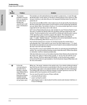
... an invalid module. Check to replace the switch. In the event log that the Link and Mode LEDs never are snug. 2. Call your ProCurve authorized LAN dealer, or use the electronic support services from ProCurve to get assistance. Troubleshooting Troubleshooting Diagnosing with the LEDs Diagnostic Tips: Tip Number ➊ Problem The power supplies installed in the switch are OK and this manual are not compatible with your ProCurve zl switch. Solution 1. If the power source and power cord are...
... an invalid module. Check to replace the switch. In the event log that the Link and Mode LEDs never are snug. 2. Call your ProCurve authorized LAN dealer, or use the electronic support services from ProCurve to get assistance. Troubleshooting Troubleshooting Diagnosing with the LEDs Diagnostic Tips: Tip Number ➊ Problem The power supplies installed in the switch are OK and this manual are not compatible with your ProCurve zl switch. Solution 1. If the power source and power cord are...
User Manual
Page 74
... that is blinking has experienced a self test or initialization fault. Download the new code and retest the module. blinking, a module The blinking LED informs you may have failed. Either the module is faulty, or it will not work properly until the switch is needed . Remove the module from the console, web browser interface, or ProCurve Manager. 5-6 See the Customer Support/Warranty card for your ProCurve authorized LAN dealer, or use the electronic support services from ProCurve to get assistance...
... that is blinking has experienced a self test or initialization fault. Download the new code and retest the module. blinking, a module The blinking LED informs you may have failed. Either the module is faulty, or it will not work properly until the switch is needed . Remove the module from the console, web browser interface, or ProCurve Manager. 5-6 See the Customer Support/Warranty card for your ProCurve authorized LAN dealer, or use the electronic support services from ProCurve to get assistance...

User Manual
Page 75
... the switch. Then reconnect switch cooling fans the power to the AC power source. See the Customer Support/ Warranty card for more of the security has been connected device that whenever a for details. 5-7 For more of the mini-GBICs supported by this table, each network port is also tested. Unsupported mini-GBICs will operate normally. ➑ A fault condition Try removing and reinstalling the power supply. supply installed in the module Installation Guide. Networking to get...
... the switch. Then reconnect switch cooling fans the power to the AC power source. See the Customer Support/ Warranty card for more of the security has been connected device that whenever a for details. 5-7 For more of the mini-GBICs supported by this table, each network port is also tested. Unsupported mini-GBICs will operate normally. ➑ A fault condition Try removing and reinstalling the power supply. supply installed in the module Installation Guide. Networking to get...
User Manual
Page 76
... cable can use the web browser interface, or ProCurve Manager network management software to any of cable must include all . You can be used . Solution Try the following procedures: • For the indicated port, verify both powered on the switch, use the console interface, or, if you have configured an IP address on and operating correctly. • Verify you have used the correct cable type for the connection. - Note: If the module configuration is not working...
... cable can use the web browser interface, or ProCurve Manager network management software to any of cable must include all . You can be used . Solution Try the following procedures: • For the indicated port, verify both powered on the switch, use the console interface, or, if you have configured an IP address on and operating correctly. • Verify you have used the correct cable type for the connection. - Note: If the module configuration is not working...
User Manual
Page 80
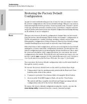
... example, configuration of VLANs, spanning tree, trunks, stacking, meshing, routing, and security. To execute the factory default reset on the front of the switch. 2. Continue to their factory default settings (usually disabling them) may become necessary to return the switch configuration to flash, release the Clear button. This process removes all switch configuration changes that you can use the console copy command. Returning the configuration of these steps: 1. This process momentarily interrupts the switch operation, clears any passwords, clears the console event log, resets...
... example, configuration of VLANs, spanning tree, trunks, stacking, meshing, routing, and security. To execute the factory default reset on the front of the switch. 2. Continue to their factory default settings (usually disabling them) may become necessary to return the switch configuration to flash, release the Clear button. This process removes all switch configuration changes that you can use the console copy command. Returning the configuration of these steps: 1. This process momentarily interrupts the switch operation, clears any passwords, clears the console event log, resets...

User Manual
Page 111
... power supply ... 1-12 basic connectivity, example topology ... 2-29 basic switch configuration IP address ... 3-3 manager password ... 3-3 subnet mask ... 3-3 Switch Setup screen ... 3-2 battery replacing battery ... 4-7 blinking LEDs error indications ... 5-4 Bootp automatic switch configuration ... 3-2 for direct console connection ... 2-27 Index - 1 Index B-3 infrastructure requirements ... 2-7 length limitations ... 2-7 required types ... 2-7 serial for in-band console access ... 2-26 buttons Clear button ... 1-10 LED Mode Select button ... 1-9 Reset button ... 1-10 C cabinet mounting...
... power supply ... 1-12 basic connectivity, example topology ... 2-29 basic switch configuration IP address ... 3-3 manager password ... 3-3 subnet mask ... 3-3 Switch Setup screen ... 3-2 battery replacing battery ... 4-7 blinking LEDs error indications ... 5-4 Bootp automatic switch configuration ... 3-2 for direct console connection ... 2-27 Index - 1 Index B-3 infrastructure requirements ... 2-7 length limitations ... 2-7 required types ... 2-7 serial for in-band console access ... 2-26 buttons Clear button ... 1-10 LED Mode Select button ... 1-9 Reset button ... 1-10 C cabinet mounting...

User Manual
Page 113
... replacing PCMCIA card ... 4-5, 4-6 front of switch Clear button ... 1-10 console port ... 1-10 description ... 1-5 LEDs ... 1-6 Mode Select button and indicator LEDs ... 1-9 Reset button ... 1-10 full-duplex fixed configuration effects on network connections ... 5-2 G Gigabit-LH ports, cables used with ... B-6 I in-band console access, types of ... 2-26 managing the switch ... 3-1 included parts ... 2-1 installation connecting the switch to a power source ... 2-21 horizontal surface mounting ... 2-20 network cable requirements ... 2-7 optional modules ... 2-9 precautions ... 2-5, 2-6 rack...
... replacing PCMCIA card ... 4-5, 4-6 front of switch Clear button ... 1-10 console port ... 1-10 description ... 1-5 LEDs ... 1-6 Mode Select button and indicator LEDs ... 1-9 Reset button ... 1-10 full-duplex fixed configuration effects on network connections ... 5-2 G Gigabit-LH ports, cables used with ... B-6 I in-band console access, types of ... 2-26 managing the switch ... 3-1 included parts ... 2-1 installation connecting the switch to a power source ... 2-21 horizontal surface mounting ... 2-20 network cable requirements ... 2-7 optional modules ... 2-9 precautions ... 2-5, 2-6 rack...

User Manual
Page 115
...power supply installation cautions ... 1-12, 2-12 installing ... 2-12 slot for modules location on switch ... 1-5 specifications connectors ... A-3 electrical ... A-3 straight-through cable pin-out ... C-8 replacing components management module battery ... 4-7 power supply ... 4-2 replacing hardware fans ... 4-4 flash memory card ... 4-5, 4-6 Reset button description ... 1-10 location on switch ... 1-5, 1-10 restoring factory default configuration ... 5-12 resetting the switch factory default reset ... 5-12 for module hot swap ... 2-28 location of cables used with ... 5-9 R rack mounting...
...power supply installation cautions ... 1-12, 2-12 installing ... 2-12 slot for modules location on switch ... 1-5 specifications connectors ... A-3 electrical ... A-3 straight-through cable pin-out ... C-8 replacing components management module battery ... 4-7 power supply ... 4-2 replacing hardware fans ... 4-4 flash memory card ... 4-5, 4-6 Reset button description ... 1-10 location on switch ... 1-5, 1-10 restoring factory default configuration ... 5-12 resetting the switch factory default reset ... 5-12 for module hot swap ... 2-28 location of cables used with ... 5-9 R rack mounting...

User Manual
Page 116
... 5-10 switch-to-device communications ... 5-11 twisted-pair cabling ... 5-11 tips for twisted-pair cables ... A-1 switch chassis LED descriptions ... 1-6 switch modules booting the switch to initialize changed module type ... 2-9 hot swapping ... 2-28 installing ... 2-9 LEDs descriptions ... 1-8 list of non-standard cables ... 5-2 link test ... 5-11 Ping test ... 5-11 Proactive Network tools ... 5-9 restoring factory default configuration ... 5-12 testing connections to other devices ... 5-11 testing end-to a power source ... 2-21 description ... 1-1 electrical specifications ...
... 5-10 switch-to-device communications ... 5-11 twisted-pair cabling ... 5-11 tips for twisted-pair cables ... A-1 switch chassis LED descriptions ... 1-6 switch modules booting the switch to initialize changed module type ... 2-9 hot swapping ... 2-28 installing ... 2-9 LEDs descriptions ... 1-8 list of non-standard cables ... 5-2 link test ... 5-11 Ping test ... 5-11 Proactive Network tools ... 5-9 restoring factory default configuration ... 5-12 testing connections to other devices ... 5-11 testing end-to a power source ... 2-21 description ... 1-1 electrical specifications ...


