
Maintenance and Service Guide
Page 2
... require upgraded and/or separately purchased hardware, drivers, software or BIOS update to find your seller. To access the latest user guides, go to http://www.hp.com/support, and follow the instructions to take full advantage of Windows. For any software product preinstalled on your seller. Legal information © Copyright 2023 HP Development Company, L.P. Nothing herein should be changed. Not all editions or versions of Windows functionality...
... require upgraded and/or separately purchased hardware, drivers, software or BIOS update to find your seller. To access the latest user guides, go to http://www.hp.com/support, and follow the instructions to take full advantage of Windows. For any software product preinstalled on your seller. Legal information © Copyright 2023 HP Development Company, L.P. Nothing herein should be changed. Not all editions or versions of Windows functionality...

Maintenance and Service Guide
Page 3
......5 Locating hardware ...5 Locating software...5 Right...5 Left ...7 Display ...8 Auto Lock and Awake...8 Low blue light mode (select products only)...9 Keyboard area ...10 Touchpad ...10 Touchpad settings ...10 Adjusting touchpad settings...10 Turning on the touchpad ...10 Touchpad components ...11 Lights ...11 Button, speakers, and fingerprint reader...13 Special keys...14 Bottom ...15 Using a SIM card (select products only)...16 Determining the correct SIM card size for your computer ...16 Inserting a nano SIM card ...16 Labels ...17 3 Illustrated parts catalog...
......5 Locating hardware ...5 Locating software...5 Right...5 Left ...7 Display ...8 Auto Lock and Awake...8 Low blue light mode (select products only)...9 Keyboard area ...10 Touchpad ...10 Touchpad settings ...10 Adjusting touchpad settings...10 Turning on the touchpad ...10 Touchpad components ...11 Lights ...11 Button, speakers, and fingerprint reader...13 Special keys...14 Bottom ...15 Using a SIM card (select products only)...16 Determining the correct SIM card size for your computer ...16 Inserting a nano SIM card ...16 Labels ...17 3 Illustrated parts catalog...
Maintenance and Service Guide
Page 4
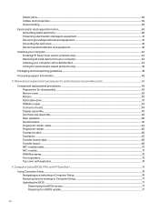
......45 Accessing support information ...46 5 Removal and replacement procedures for authorized service provider parts 48 Component replacement procedures ...48 Preparation for disassembly...48 Bottom cover ...48 Battery ...50 Solid-state drive...51 WWAN module...53 Connector board...54 Display assembly...55 Fan/heat sink assembly...58 Rear speakers...60 System board ...61 Fingerprint reader cable...64 Fingerprint reader...65 Touchpad cable...66 Touchpad ...67 Transfer board cable ...68 Transfer board...69 NFC module cable...70 NFC module ...71...
......45 Accessing support information ...46 5 Removal and replacement procedures for authorized service provider parts 48 Component replacement procedures ...48 Preparation for disassembly...48 Bottom cover ...48 Battery ...50 Solid-state drive...51 WWAN module...53 Connector board...54 Display assembly...55 Fan/heat sink assembly...58 Rear speakers...60 System board ...61 Fingerprint reader cable...64 Fingerprint reader...65 Touchpad cable...66 Touchpad ...67 Transfer board cable ...68 Transfer board...69 NFC module cable...70 NFC module ...71...

Maintenance and Service Guide
Page 5
... 84 Downloading HP Hardware Diagnostics Windows by product name or number (select products only) ...85 Installing HP PC Hardware Diagnostics Windows...85 Using HP PC Hardware Diagnostics UEFI ...85 Using an HP PC Hardware Diagnostics UEFI hardware failure ID code 85 Starting HP PC Hardware Diagnostics UEFI ...85 Starting HP PC Hardware Diagnostics UEFI through HP Hotkey Support software (select products only)...86 Downloading HP PC Hardware Diagnostics UEFI to a USB flash drive 86 Downloading the latest HP PC Hardware Diagnostics UEFI version 87 Downloading HP PC Hardware Diagnostics...
... 84 Downloading HP Hardware Diagnostics Windows by product name or number (select products only) ...85 Installing HP PC Hardware Diagnostics Windows...85 Using HP PC Hardware Diagnostics UEFI ...85 Using an HP PC Hardware Diagnostics UEFI hardware failure ID code 85 Starting HP PC Hardware Diagnostics UEFI ...85 Starting HP PC Hardware Diagnostics UEFI through HP Hotkey Support software (select products only)...86 Downloading HP PC Hardware Diagnostics UEFI to a USB flash drive 86 Downloading the latest HP PC Hardware Diagnostics UEFI version 87 Downloading HP PC Hardware Diagnostics...

Maintenance and Service Guide
Page 14
... Sleep state. Select the Start button, select Settings, select System, and then select Power & battery. 2. Connects a display device that has a USB Type-C connector, Thunderbolt port with HP Sleep and Charge supplying power to the computer and, if needed, charging the and DisplayPort output computer battery. - Select Screen and sleep, and then follow the on by default. Table 2-2 Left-side components and their descriptions (continued) Component Description (3) USB Type-C power connector and Connects an AC adapter that has a USB Type...
... Sleep state. Select the Start button, select Settings, select System, and then select Power & battery. 2. Connects a display device that has a USB Type-C connector, Thunderbolt port with HP Sleep and Charge supplying power to the computer and, if needed, charging the and DisplayPort output computer battery. - Select Screen and sleep, and then follow the on by default. Table 2-2 Left-side components and their descriptions (continued) Component Description (3) USB Type-C power connector and Connects an AC adapter that has a USB Type...

Maintenance and Service Guide
Page 16
... video, and record still images. Table 2-3 Display components and their descriptions (continued) Component Description (5) Cameras (2) Allow you to the clamshell mode. Auto Lock and Awake is disabled in front of the computer. NOTE: The keyboard, including the function keys and power key (select products only), is turned on your product. (6) User-proximity sensor Uses the Auto Lock and Awake feature to monitor your country or region. Adjusting touchpad settings Use...
... video, and record still images. Table 2-3 Display components and their descriptions (continued) Component Description (5) Cameras (2) Allow you to the clamshell mode. Auto Lock and Awake is disabled in front of the computer. NOTE: The keyboard, including the function keys and power key (select products only), is turned on your product. (6) User-proximity sensor Uses the Auto Lock and Awake feature to monitor your country or region. Adjusting touchpad settings Use...
Maintenance and Service Guide
Page 52
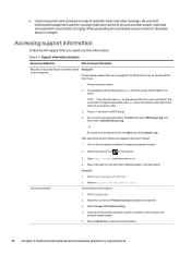
... over Problem solving to www.hp.com. 2. Immediately and repeatedly press esc when the power button light turns white. Type the serial number, product number, or product name to go to open. 2. ● Use transporters and conveyors made of reported failure incidents stored on the computer and allow the operating system to the product support page. 5. Table 4-3 Support information locations Service consideration Path to dissipate electric charges. To...
... over Problem solving to www.hp.com. 2. Immediately and repeatedly press esc when the power button light turns white. Type the serial number, product number, or product name to go to open. 2. ● Use transporters and conveyors made of reported failure incidents stored on the computer and allow the operating system to the product support page. 5. Table 4-3 Support information locations Service consideration Path to dissipate electric charges. To...

Maintenance and Service Guide
Page 54
... model, serial number, product key, and length of each screw size and location during removal and replacement. IMPORTANT: Only an authorized service provider should access the components described in this chapter. You must remove, replace, or loosen as many as 46 screws when you are on -screen instructions. Turn off or in this procedure and illustration. 48 Chapter 5 Removal and replacement procedures for authorized service provider parts. 5 Removal and replacement...
... model, serial number, product key, and length of each screw size and location during removal and replacement. IMPORTANT: Only an authorized service provider should access the components described in this chapter. You must remove, replace, or loosen as many as 46 screws when you are on -screen instructions. Turn off or in this procedure and illustration. 48 Chapter 5 Removal and replacement procedures for authorized service provider parts. 5 Removal and replacement...
Maintenance and Service Guide
Page 59
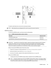
... module antenna cables (1) from the system board (see Preparation for use this procedure and illustration. Disconnect the battery cable from the WWAN module. Connect the antenna cable to four WWAN module antenna cables. NOTE: Computer models have tags that identify them with a number that regulates wireless devices in the computer by the governmental agency that corresponds to restore device functionality, and then contact technical support. WWAN module To remove the WWAN module, use...
... module antenna cables (1) from the system board (see Preparation for use this procedure and illustration. Disconnect the battery cable from the WWAN module. Connect the antenna cable to four WWAN module antenna cables. NOTE: Computer models have tags that identify them with a number that regulates wireless devices in the computer by the governmental agency that corresponds to restore device functionality, and then contact technical support. WWAN module To remove the WWAN module, use...
Maintenance and Service Guide
Page 68
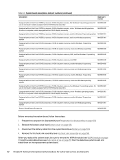
..., 16 GB of system memory, and a non-Windows operating system N46501-001 System Board Repair Support Kit N19699-888 Before removing the system board, follow these steps: 1. Remove the bottom cover (see Solid-state drive on page 51) from the system board (see Preparation for authorized service provider parts When you replace the system board, be sure to remove the WWAN module (see WWAN module on page 53) and...
..., 16 GB of system memory, and a non-Windows operating system N46501-001 System Board Repair Support Kit N19699-888 Before removing the system board, follow these steps: 1. Remove the bottom cover (see Solid-state drive on page 51) from the system board (see Preparation for authorized service provider parts When you replace the system board, be sure to remove the WWAN module (see WWAN module on page 53) and...

Maintenance and Service Guide
Page 83
... Apply Factory Defaults and Exit. Or you must then press enter. During the download and installation, follow these instructions: Restoring factory settings in an optional docking device, or connected to reliable external power using the AC adapter. NOTE: Your password settings and security settings are packaged in Windows, you restore the factory settings. See Using Computer Setup on page 76. 2. Preparing for a BIOS update on battery power, docked in Computer Setup 77 See Using Computer Setup on page 76. 2. Most BIOS updates on your changes...
... Apply Factory Defaults and Exit. Or you must then press enter. During the download and installation, follow these instructions: Restoring factory settings in an optional docking device, or connected to reliable external power using the AC adapter. NOTE: Your password settings and security settings are packaged in Windows, you restore the factory settings. See Using Computer Setup on page 76. 2. Preparing for a BIOS update on battery power, docked in Computer Setup 77 See Using Computer Setup on page 76. 2. Most BIOS updates on your changes...
Maintenance and Service Guide
Page 84
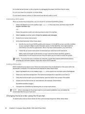
... computer or initiate Sleep. Select your computer to install the update. Changing the boot order using the f9 prompt To dynamically choose a boot device for example, filename.exe). Downloading a BIOS update After you review the prerequisites, you can check for updates and messages. 3. You will need this path when you are displayed, follow these steps: a. Complete the installation by unplugging the power cord from your hard drive. Make a note of the...
... computer or initiate Sleep. Select your computer to install the update. Changing the boot order using the f9 prompt To dynamically choose a boot device for example, filename.exe). Downloading a BIOS update After you review the prerequisites, you can check for updates and messages. 3. You will need this path when you are displayed, follow these steps: a. Complete the installation by unplugging the power cord from your hard drive. Make a note of the...

Maintenance and Service Guide
Page 88
... keyboards, turn on or restart the computer or tablet, quickly press esc, and then press f9 for boot options. ● For tablets without installed recovery software. Using HP Sure Recover, an administrator or user can restore the system and install: ● Latest version of the operating system ● Platform-specific device drivers ● Software applications, in BIOS for HP Sure Recover, go to a working state sooner than using the HP Recovery media, you obtain and use the HP recovery discs. Using a recent backup...
... keyboards, turn on or restart the computer or tablet, quickly press esc, and then press f9 for boot options. ● For tablets without installed recovery software. Using HP Sure Recover, an administrator or user can restore the system and install: ● Latest version of the operating system ● Platform-specific device drivers ● Software applications, in BIOS for HP Sure Recover, go to a working state sooner than using the HP Recovery media, you obtain and use the HP recovery discs. Using a recent backup...
Maintenance and Service Guide
Page 89
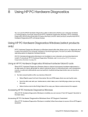
... Downloading HP PC Hardware Diagnostics Windows on your failure code and send it . Using HP PC Hardware Diagnostics Windows (select products only) HP PC Hardware Diagnostics Windows is a Windows-based utility that requires hardware replacement, a 24-digit failure ID code is installed, you must perform troubleshooting steps before you can receive a failure ID. ■ You have several options after you receive a failure ID: ● Select Next to open the Event Automation Service...
... Downloading HP PC Hardware Diagnostics Windows on your failure code and send it . Using HP PC Hardware Diagnostics Windows (select products only) HP PC Hardware Diagnostics Windows is a Windows-based utility that requires hardware replacement, a 24-digit failure ID code is installed, you must perform troubleshooting steps before you can receive a failure ID. ■ You have several options after you receive a failure ID: ● Select Next to open the Event Automation Service...
Maintenance and Service Guide
Page 91
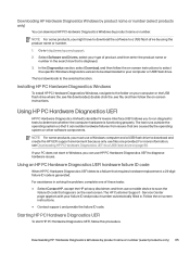
... Downloading HP PC Hardware Diagnostics UEFI to a USB flash drive on -screen instructions to select the specific Windows diagnostics version to be downloaded to your type of these tasks: ● Select Contact HP, accept the HP privacy disclaimer, and then use a mobile device to download and create the HP UEFI support environment because only .exe files are caused by product name or number. Using an HP PC Hardware Diagnostics UEFI hardware failure ID code When HP PC Hardware...
... Downloading HP PC Hardware Diagnostics UEFI to a USB flash drive on -screen instructions to select the specific Windows diagnostics version to be downloaded to your type of these tasks: ● Select Contact HP, accept the HP privacy disclaimer, and then use a mobile device to download and create the HP UEFI support environment because only .exe files are caused by product name or number. Using an HP PC Hardware Diagnostics UEFI hardware failure ID code When HP PC Hardware...

Maintenance and Service Guide
Page 100
... typical operation, the only user data stored on Chip (SoC) Unplug unit from main power, remove top cover and press Clear CMOS button Keyboard/mouse (ROM) Non-volatile, 2 KB embedded in Yes N/A the super I/O controller (SIO2) Keyboard/mouse (RAM) Volatile, 256 bytes embedded in No the super I/O controller (SIO2) Unplug unit from main power LOM EEPROM Non-volatile, 2 MB embedded in BIOS Settings are preferences for device configuration and settings for connections. iv...
... typical operation, the only user data stored on Chip (SoC) Unplug unit from main power, remove top cover and press Clear CMOS button Keyboard/mouse (ROM) Non-volatile, 2 KB embedded in Yes N/A the super I/O controller (SIO2) Keyboard/mouse (RAM) Volatile, 256 bytes embedded in No the super I/O controller (SIO2) Unplug unit from main power LOM EEPROM Non-volatile, 2 MB embedded in BIOS Settings are preferences for device configuration and settings for connections. iv...

Maintenance and Service Guide
Page 101
... firmware management and recovery software. HP has provided options in Computer Setup (BIOS) to allow you can use a utility to write to the chip. 4. The restore defaults feature does not reset the Custom Secure Boot keys. Turn on -screen instructions. 2. In addition, the UEFI BIOS works to initialize the computer's hardware before an OS is meant by "Restore the nonvolatile memory found in a computer. What kind of software programs from a legacy BIOS? The DIMM SPD memory...
... firmware management and recovery software. HP has provided options in Computer Setup (BIOS) to allow you can use a utility to write to the chip. 4. The restore defaults feature does not reset the Custom Secure Boot keys. Turn on -screen instructions. 2. In addition, the UEFI BIOS works to initialize the computer's hardware before an OS is meant by "Restore the nonvolatile memory found in a computer. What kind of software programs from a legacy BIOS? The DIMM SPD memory...

Maintenance and Service Guide
Page 107
... bottom 15 display 8, 9 keyboard area 10 left side 7 right side 5 Computer Setup navigating and selecting 76 restoring factory settings 77 starting 76 computer specifications 89 connector board illustrated 31 removal 54 spare part numbers 31, 54 connector board cable illustrated 34 spare part number 34 connector, power 6, 8 D display specifications 89, 90 display assembly illustrated 21 removal 55 spare part numbers 21, 55 display components 8, 9 display panel product description 1 dock, spare part numbers 35 duck head adapter, spare part numbers 36 E electrostatic...
... bottom 15 display 8, 9 keyboard area 10 left side 7 right side 5 Computer Setup navigating and selecting 76 restoring factory settings 77 starting 76 computer specifications 89 connector board illustrated 31 removal 54 spare part numbers 31, 54 connector board cable illustrated 34 spare part number 34 connector, power 6, 8 D display specifications 89, 90 display assembly illustrated 21 removal 55 spare part numbers 21, 55 display components 8, 9 display panel product description 1 dock, spare part numbers 35 duck head adapter, spare part numbers 36 E electrostatic...
Maintenance and Service Guide
Page 108
... H hard drive specifications 89 hardware, locating 5 HDMI port, identifying 7 heat sink illustrated 31 spare part numbers 31 HP PC Hardware Diagnostics UEFI downloading 86 failure ID code 85 HP Hotkey Support software 86 starting 85, 86 using 85 HP PC Hardware Diagnostics Windows accessing 83, 84 downloading 84 failure ID code 83 installing 85 using 83 HP Recovery media recovery 81 HP Sure Recover 82 HP Sure Start 92, 96 hub, spare part numbers 36 I illustrated parts catalog 20 internal microphones, identifying 9 interposer board illustrated 33 removal 55 spare part number 33, 55 J jacks audio...
... H hard drive specifications 89 hardware, locating 5 HDMI port, identifying 7 heat sink illustrated 31 spare part numbers 31 HP PC Hardware Diagnostics UEFI downloading 86 failure ID code 85 HP Hotkey Support software 86 starting 85, 86 using 85 HP PC Hardware Diagnostics Windows accessing 83, 84 downloading 84 failure ID code 83 installing 85 using 83 HP Recovery media recovery 81 HP Sure Recover 82 HP Sure Start 92, 96 hub, spare part numbers 36 I illustrated parts catalog 20 internal microphones, identifying 9 interposer board illustrated 33 removal 55 spare part number 33, 55 J jacks audio...
Maintenance and Service Guide
Page 109
pointing device 3 ports 2 power requirements 3 processors 1 product name 1 security 3 sensors 3 serviceability 4 storage 2 video 2 wireless 2 product name 1 R rear speakers illustrated 31 removal 60 spare part number 31, 60 recovery 80, 81 discs 81 media 81 USB flash drive 81 recovery media 80 creating using HP Cloud Recovery Download Tool 80 creating using Windows tools 80 Remote HP PC Hardware Diagnostics UEFI settings customizing 88 using 87 removal and replacement procedures 48 removing personal data from volatile system memory 92 restoring 80 restoring and recovery methods 81 right side...
pointing device 3 ports 2 power requirements 3 processors 1 product name 1 security 3 sensors 3 serviceability 4 storage 2 video 2 wireless 2 product name 1 R rear speakers illustrated 31 removal 60 spare part number 31, 60 recovery 80, 81 discs 81 media 81 USB flash drive 81 recovery media 80 creating using HP Cloud Recovery Download Tool 80 creating using Windows tools 80 Remote HP PC Hardware Diagnostics UEFI settings customizing 88 using 87 removal and replacement procedures 48 removing personal data from volatile system memory 92 restoring 80 restoring and recovery methods 81 right side...


