
Service Manual
Page 8
...Axis Motor Assembly 8-29 Cutter Assembly 8-32 Left Encoder Holder 8-33 Cutter Bushing 8-35 Cutter Guide Bracket 8-36 Drive Roller Encoder Sensor 8-38 Trailing Cable 8-40 Ink Supply Station 8-48 Interconnect PCA 8-50 Service Station and Aerosol Fan 8-52 Cutter Guide 8-55 Print Platen 8-56 Service Station Holder... 8-57 Interconnect Cable 8-59 Ink Supply Tubes 8-60 Vacuum Fan 8-64 Pinch-Arm 8-66 Pinch-Arm Mechanism 8-67 Pinch-Arm Lever 8-69 6 HP DesignJets 500 and 800 Series Printers Service Manual
...Axis Motor Assembly 8-29 Cutter Assembly 8-32 Left Encoder Holder 8-33 Cutter Bushing 8-35 Cutter Guide Bracket 8-36 Drive Roller Encoder Sensor 8-38 Trailing Cable 8-40 Ink Supply Station 8-48 Interconnect PCA 8-50 Service Station and Aerosol Fan 8-52 Cutter Guide 8-55 Print Platen 8-56 Service Station Holder... 8-57 Interconnect Cable 8-59 Ink Supply Tubes 8-60 Vacuum Fan 8-64 Pinch-Arm 8-66 Pinch-Arm Mechanism 8-67 Pinch-Arm Lever 8-69 6 HP DesignJets 500 and 800 Series Printers Service Manual
Service Manual
Page 28
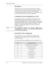
... 07 08 11 Component/System Main PCA/Electronics Module Carriage/Carriage PCA Power Supply Unit Network Card Formatter Hard Disk Drive Interconnect PCA Front Panel Trailing Cable 2-2 HP DesignJets 500 and 800 Series Printers Service Manual The following pages contain a list of the Error Codes are hexa-decimal based numbers generally caused by...
... 07 08 11 Component/System Main PCA/Electronics Module Carriage/Carriage PCA Power Supply Unit Network Card Formatter Hard Disk Drive Interconnect PCA Front Panel Trailing Cable 2-2 HP DesignJets 500 and 800 Series Printers Service Manual The following pages contain a list of the Error Codes are hexa-decimal based numbers generally caused by...
Service Manual
Page 36
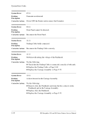
n Replace the Carriage Assembly ⇒ Page 8-78. 2-10 HP DesignJets 500 and 800 Series Printers Service Manual n Replace the Carriage Assembly ⇒ Page 8-78. Corrective Action: Try the following : n Remove ALL the Printheads...Printheads and in the Carriage Assembly. Corrective Action: Power OFF the Printer and reconnect the Formatter. Corrective Action: Reconnect the Front Panel. n Replace the Trailing Cable ⇒ Page 8-40. System Error: 08:11 Problem Description: Front Panel cannot be detected. Corrective Action: Try the following : n Check that the...
n Replace the Carriage Assembly ⇒ Page 8-78. 2-10 HP DesignJets 500 and 800 Series Printers Service Manual n Replace the Carriage Assembly ⇒ Page 8-78. Corrective Action: Try the following : n Remove ALL the Printheads...Printheads and in the Carriage Assembly. Corrective Action: Power OFF the Printer and reconnect the Formatter. Corrective Action: Reconnect the Front Panel. n Replace the Trailing Cable ⇒ Page 8-40. System Error: 08:11 Problem Description: Front Panel cannot be detected. Corrective Action: Try the following : n Check that the...
Service Manual
Page 156
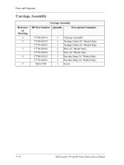
Parts and Diagrams Carriage Assembly Reference on Drawing 1 2 3 4 5 Carriage Assembly HP Part Number Quantity Description/Comments C7769-60151 C7769-60147 C7770-60147 C7769-60182 C7770-60014 C7769-60183 C7770-60013 0624-0769 1 Carriage Assembly 1 Trailing Cable (24" Model Only) 1 Trailing Cable (42" Model Only) 1 Belt (24" Model Only) 1 Belt (42" Model Only) 1 Encoder Strip (24" Model Only) 1 Encoder Strip (42" Model Only) 1 Screw 7-34 HP DesignJets 500 and 800 Series Printers Service Manual
Parts and Diagrams Carriage Assembly Reference on Drawing 1 2 3 4 5 Carriage Assembly HP Part Number Quantity Description/Comments C7769-60151 C7769-60147 C7770-60147 C7769-60182 C7770-60014 C7769-60183 C7770-60013 0624-0769 1 Carriage Assembly 1 Trailing Cable (24" Model Only) 1 Trailing Cable (42" Model Only) 1 Belt (24" Model Only) 1 Belt (42" Model Only) 1 Encoder Strip (24" Model Only) 1 Encoder Strip (42" Model Only) 1 Screw 7-34 HP DesignJets 500 and 800 Series Printers Service Manual

Service Manual
Page 167
... Assembly 8-32 Left Encoder Holder 8-33 Cutter Bushing 8-35 Cutter Guide Bracket 8-36 Drive Roller Encoder Sensor 8-38 Trailing Cable 8-40 Ink Supply Station 8-48 Interconnect PCA 8-50 Service Station and Aerosol Fan 8-52 Cutter Guide 8-55 Print ...Platen 8-56 Service Station Holder 8-57 Interconnect Cable 8-59 Ink Supply Tubes 8-60 Vacuum Fan 8-64 Pinch-Arm 8-66 Pinch-Arm Mechanism 8-67 Pinch-Arm Lever...) 8-78 Paper-Axis Motor 8-84 Drive Roller 8-86 Gear Assemblies 8-92 HP DesignJets 500 and 800 Series Printers Service Manual 8-1
... Assembly 8-32 Left Encoder Holder 8-33 Cutter Bushing 8-35 Cutter Guide Bracket 8-36 Drive Roller Encoder Sensor 8-38 Trailing Cable 8-40 Ink Supply Station 8-48 Interconnect PCA 8-50 Service Station and Aerosol Fan 8-52 Cutter Guide 8-55 Print ...Platen 8-56 Service Station Holder 8-57 Interconnect Cable 8-59 Ink Supply Tubes 8-60 Vacuum Fan 8-64 Pinch-Arm 8-66 Pinch-Arm Mechanism 8-67 Pinch-Arm Lever...) 8-78 Paper-Axis Motor 8-84 Drive Roller 8-86 Gear Assemblies 8-92 HP DesignJets 500 and 800 Series Printers Service Manual 8-1

Service Manual
Page 200
Remove the Left Encoder Holder, making sure that you first unclip both the Trailing Cable and the Interconnect Cable. 8-34 HP DesignJets 500 and 800 Series Printers Service Manual Remove the Electronics Module Refer to Page 8-24. 6. Remove 2 T-20 screws (Type A) from the Left Encoder Holder. 7. Disconnect the Trailing Cable and unclip the Ferrite and remove. 5. Removal and Installation 4.
Remove the Left Encoder Holder, making sure that you first unclip both the Trailing Cable and the Interconnect Cable. 8-34 HP DesignJets 500 and 800 Series Printers Service Manual Remove the Electronics Module Refer to Page 8-24. 6. Remove 2 T-20 screws (Type A) from the Left Encoder Holder. 7. Disconnect the Trailing Cable and unclip the Ferrite and remove. 5. Removal and Installation 4.
Service Manual
Page 206
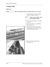
Refer to Page 8-5. 3. Refer to Page 4-22. Perform the Service Utility "Unlock Carriage" - NOTE Switch off the Printer after performing this Utility. 2. Remove the Left Hand Cover - Release the latch and lift up the Carriage Cover. 8-40 HP DesignJets 500 and 800 Series Printers Service Manual Remove the Top Cover and Window Refer to remove the Tubes Assembly from the Carriage. 5. Manually move the carriage to the correct position to Page 8-10. 4. Removal and Installation Trailing Cable Removal NOTE Refer to the table on Page 8-4 for information on screw types. 1.
Refer to Page 8-5. 3. Refer to Page 4-22. Perform the Service Utility "Unlock Carriage" - NOTE Switch off the Printer after performing this Utility. 2. Remove the Left Hand Cover - Release the latch and lift up the Carriage Cover. 8-40 HP DesignJets 500 and 800 Series Printers Service Manual Remove the Top Cover and Window Refer to remove the Tubes Assembly from the Carriage. 5. Manually move the carriage to the correct position to Page 8-10. 4. Removal and Installation Trailing Cable Removal NOTE Refer to the table on Page 8-4 for information on screw types. 1.

Service Manual
Page 209
Slide the Trailing Cable out of the clip inside the Carriage Assembly and then 2 lift up to free it from the Carriage Assembly. 14. Remove the clip securing the Trailing Cable. 13. Disconnect the Trailing Cable from the Carriage. 1 HP DesignJets 500 and 800 Series Printers Service Manual 8-43 Remove Removal and Installation 12.
Slide the Trailing Cable out of the clip inside the Carriage Assembly and then 2 lift up to free it from the Carriage Assembly. 14. Remove the clip securing the Trailing Cable. 13. Disconnect the Trailing Cable from the Carriage. 1 HP DesignJets 500 and 800 Series Printers Service Manual 8-43 Remove Removal and Installation 12.

Service Manual
Page 210
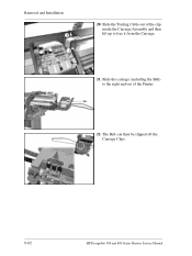
Slide the Plastic Holder, that kept the Trailing Cable flat, to the right to the right so that secure the Trailing Cable. 17. Move the Carriage Assembly to release it from the retaining clip. 8-44 HP DesignJets 500 and 800 Series Printers Service Manual Release ALL the clips on the beam that the Trailing Cable clips on the beam are visible. 16. Removal and Installation 15.
Slide the Plastic Holder, that kept the Trailing Cable flat, to the right to the right so that secure the Trailing Cable. 17. Move the Carriage Assembly to release it from the retaining clip. 8-44 HP DesignJets 500 and 800 Series Printers Service Manual Release ALL the clips on the beam that the Trailing Cable clips on the beam are visible. 16. Removal and Installation 15.

Service Manual
Page 211
Remove the Plastic Holder from the Electronics Module. Disconnect the Trailing Cable from the Printer. 19. HP DesignJets 500 and 800 Series Printers Service Manual 8-45 Removal and Installation 18. Release the Trailing Cable clips. 20.
Remove the Plastic Holder from the Electronics Module. Disconnect the Trailing Cable from the Printer. 19. HP DesignJets 500 and 800 Series Printers Service Manual 8-45 Removal and Installation 18. Release the Trailing Cable clips. 20.

Service Manual
Page 212
Removal and Installation 21. Slide the Trailing Cable through the Carriage Assembly and remove. 8-46 HP DesignJets 500 and 800 Series Printers Service Manual Unclip the Ferrite and remove. 22.
Removal and Installation 21. Slide the Trailing Cable through the Carriage Assembly and remove. 8-46 HP DesignJets 500 and 800 Series Printers Service Manual Unclip the Ferrite and remove. 22.

Service Manual
Page 213
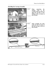
Align HP DesignJets 500 and 800 Series Printers Service Manual 8-47 Installing the Trailing Cable Align Removal and Installation NOTE When installing the Trailing Cable, make sure that you align the red lines on the Trailing Cable as shown in these drawings.
Align HP DesignJets 500 and 800 Series Printers Service Manual 8-47 Installing the Trailing Cable Align Removal and Installation NOTE When installing the Trailing Cable, make sure that you align the red lines on the Trailing Cable as shown in these drawings.

Service Manual
Page 247
HP DesignJets 500 and 800 Series Printers Service Manual 8-81 Disconnect the Trailing Cable from the Carriage Assembly. Removal and Installation 17. Unclip the Carriage Cover (clip located on the left hand side of the Carriage use a screwdriver if necessary). Remove 18. Remove the clip securing the Trailing Cable. 19.
HP DesignJets 500 and 800 Series Printers Service Manual 8-81 Disconnect the Trailing Cable from the Carriage Assembly. Removal and Installation 17. Unclip the Carriage Cover (clip located on the left hand side of the Carriage use a screwdriver if necessary). Remove 18. Remove the clip securing the Trailing Cable. 19.
Service Manual
Page 248
The Belt can then be slipped off the Carriage Clips. 8-82 HP DesignJets 500 and 800 Series Printers Service Manual Removal and Installation 2 1 20. Slide the carriage (including the Belt) to free it from the Carriage. 21. Slide the Trailing Cable out of the clip inside the Carriage Assembly and then lift up to the right and out of the Printer. 22.
The Belt can then be slipped off the Carriage Clips. 8-82 HP DesignJets 500 and 800 Series Printers Service Manual Removal and Installation 2 1 20. Slide the carriage (including the Belt) to free it from the Carriage. 21. Slide the Trailing Cable out of the clip inside the Carriage Assembly and then lift up to the right and out of the Printer. 22.
Service Manual
Page 249
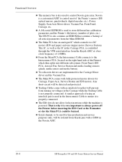
Align NOTE When installing the Belt, make sure that you align the red lines on the Trailing Cable as shown in this drawing. Scan-Axis Motor Tensioner HP DesignJets 500 and 800 Series Printers Service Manual 8-83 Removal and Installation Installing the Carriage Assembly Align NOTE When connecting the Trailing Cable to the Carriage, make sure that you insert it into the Carriage as shown in this drawing.
Align NOTE When installing the Belt, make sure that you align the red lines on the Trailing Cable as shown in this drawing. Scan-Axis Motor Tensioner HP DesignJets 500 and 800 Series Printers Service Manual 8-83 Removal and Installation Installing the Carriage Assembly Align NOTE When connecting the Trailing Cable to the Carriage, make sure that you insert it into the Carriage as shown in this drawing.
Service Manual
Page 268
...is also used to the Interconnect PCA (located on voltages in the Navata ASIC. 10-4 HP DesignJets 500 and 800 Series Printers Service Manual Navata is a customized ASIC to be burned. n Trailing Cables come with an interlock loop that contains a backup of 1.6MHz. n Two discrete drivers are... be isolated from the Main EEROM. n From the Main PCA the Interconnect Cable connects to control Navata gate array. n The Main PCA comes with a GPIO in the Carriage while the Trailing Cable is very important to store different line calibration parameters and the Printer's life ...
...is also used to the Interconnect PCA (located on voltages in the Navata ASIC. 10-4 HP DesignJets 500 and 800 Series Printers Service Manual Navata is a customized ASIC to be burned. n Trailing Cables come with an interlock loop that contains a backup of 1.6MHz. n Two discrete drivers are... be isolated from the Main EEROM. n From the Main PCA the Interconnect Cable connects to control Navata gate array. n The Main PCA comes with a GPIO in the Carriage while the Trailing Cable is very important to store different line calibration parameters and the Printer's life ...
Service Manual
Page 280
... Air Pressurization System 8-20 Carriage Assembly 8-51 Electronics Module 8-27 Platen Assembly 8-63 Right Hand Cover 8-6 Trailing Cable 8-40 Interface Specifications 10-17 ISS Assembly 7-14 G Gear Assemblies 8-92 I Ink Cartridge Error Message 3-6... Carriage Assembly 8-83 Electronics Module 8-26 Scan-Axis Motor Assembly 8-31 Service Station/Aerosol Fan 8-54 Trailing Cable 8-47 Interconnect Cable 8-59 L LAN Card 8-21 Left Encoder Holder 8-33 Left End Roll-Feed 8-13 Left Hand ... P Paper Advance Test 4-10 Paper-Axis Motor 8-84 Index-2 HP DesignJets 500 and 800 Series Printers Service Manual
... Air Pressurization System 8-20 Carriage Assembly 8-51 Electronics Module 8-27 Platen Assembly 8-63 Right Hand Cover 8-6 Trailing Cable 8-40 Interface Specifications 10-17 ISS Assembly 7-14 G Gear Assemblies 8-92 I Ink Cartridge Error Message 3-6... Carriage Assembly 8-83 Electronics Module 8-26 Scan-Axis Motor Assembly 8-31 Service Station/Aerosol Fan 8-54 Trailing Cable 8-47 Interconnect Cable 8-59 L LAN Card 8-21 Left Encoder Holder 8-33 Left End Roll-Feed 8-13 Left Hand ... P Paper Advance Test 4-10 Paper-Axis Motor 8-84 Index-2 HP DesignJets 500 and 800 Series Printers Service Manual
Service Manual
Page 282
...Station Holder 8-57 Print Quality Problems 1-3 Service Station/Aerosol Fan 8-52 Solving Print Quality Problems 1-3 Spittoon 8-23 Spittoon 8-23 Trailing Cable 8-40 System Error Codes Vacuum Fan 8-64 0110 2-7 Window and Top Cover 8-10 0111 2-7 Required Tools 8-3 0112 2-7 ...0510 Error 2-9 Scan-axis Maintenance 9-4 0510 Warning 2-9 Scan-Axis Motor Assembly 8-29 0511 2-10 Scheduled Maintenance 9-3 0811 2-10 Index-4 HP DesignJets 500 and 800 Series Printers Service Manual Index Drive Roller Encoder Sensor 8-38 Scratching 6-10 Electronics Module 8-24 Screw Types 8-4 Encoder...
...Station Holder 8-57 Print Quality Problems 1-3 Service Station/Aerosol Fan 8-52 Solving Print Quality Problems 1-3 Spittoon 8-23 Spittoon 8-23 Trailing Cable 8-40 System Error Codes Vacuum Fan 8-64 0110 2-7 Window and Top Cover 8-10 0111 2-7 Required Tools 8-3 0112 2-7 ...0510 Error 2-9 Scan-axis Maintenance 9-4 0510 Warning 2-9 Scan-Axis Motor Assembly 8-29 0511 2-10 Scheduled Maintenance 9-3 0811 2-10 Index-4 HP DesignJets 500 and 800 Series Printers Service Manual Index Drive Roller Encoder Sensor 8-38 Scratching 6-10 Electronics Module 8-24 Screw Types 8-4 Encoder...

Service Manual
Page 283
... 6-4 No Defects Found 6-8 Tubes Assembly 10-9 Turn Drive Roller 4-21 U Unlock Carriage 4-22 V Vacuum Fan 8-64 Vertical Line Straightness Problems 5-5 W Window and Top Cover 8-10 T Trailing Cable 8-40 Troubleshooting Boot-Up Sequence 1-12 Color differences 1-6 Formatter/Accessory Card LEDs 1-14 Media Jams 1-4 Paper-Axis Shutdowns 1-4 Power Switch LED 1-10 Priming Procedure...
... 6-4 No Defects Found 6-8 Tubes Assembly 10-9 Turn Drive Roller 4-21 U Unlock Carriage 4-22 V Vacuum Fan 8-64 Vertical Line Straightness Problems 5-5 W Window and Top Cover 8-10 T Trailing Cable 8-40 Troubleshooting Boot-Up Sequence 1-12 Color differences 1-6 Formatter/Accessory Card LEDs 1-14 Media Jams 1-4 Paper-Axis Shutdowns 1-4 Power Switch LED 1-10 Priming Procedure...


