Service Manual
Page 9
... PCAs 343 Stapler/stacker stapler assembly 344 Stacker and stapler/stacker switches and sensors 345 Stacker and stapler/stacker motors and solenoids 346 Stacker and stapler/stacker PCAs 347 Printer and accessory wiring diagrams 348 DC controller block diagram 356 General timing diagrams 357 8 Parts and diagrams Ordering parts, supplies, and getting...
... PCAs 343 Stapler/stacker stapler assembly 344 Stacker and stapler/stacker switches and sensors 345 Stacker and stapler/stacker motors and solenoids 346 Stacker and stapler/stacker PCAs 347 Printer and accessory wiring diagrams 348 DC controller block diagram 356 General timing diagrams 357 8 Parts and diagrams Ordering parts, supplies, and getting...
Service Manual
Page 11
...stacker 102 Figure 33. Staple mode feed and delivery diagram (6 of 6 110 Figure 40. Image formation block diagram 119 Figure 51. Laser control circuit block diagram 77 Figure 14. Stapler/stacker driver PCA block diagram 106 Figure 36. Staple mode feed and delivery diagram (3 ... only 62 Figure 6. High-voltage circuit block diagram 73 Figure 11. List of 2 61 Figure 5. Printer paper pickup and feed block diagram 78 Figure 15. Stapler/stacker motors, solenoids, and sensors block diagram 108 Figure 37. Staple mode feed and delivery diagram (2 of 3 115 Figure...
...stacker 102 Figure 33. Staple mode feed and delivery diagram (6 of 6 110 Figure 40. Image formation block diagram 119 Figure 51. Laser control circuit block diagram 77 Figure 14. Stapler/stacker driver PCA block diagram 106 Figure 36. Staple mode feed and delivery diagram (3 ... only 62 Figure 6. High-voltage circuit block diagram 73 Figure 11. List of 2 61 Figure 5. Printer paper pickup and feed block diagram 78 Figure 15. Stapler/stacker motors, solenoids, and sensors block diagram 108 Figure 37. Staple mode feed and delivery diagram (2 of 3 115 Figure...
Service Manual
Page 14
... (1 of 4 335 Figure 213. Location of main printer parts (4 of 4 332 Figure 210. Location of 500-sheet paper feeder switches, sensors, solenoids, and PCAs . . . 340 Figure 218. Paper-pickup assembly 379 Figure 245. Location of 1,500-sheet switches, sensors, solenoids, and PCAs 343 Figure 221. HP LaserJet 4300 general timing diagram 358 Figure 236. Location of...
... (1 of 4 335 Figure 213. Location of main printer parts (4 of 4 332 Figure 210. Location of 500-sheet paper feeder switches, sensors, solenoids, and PCAs . . . 340 Figure 218. Paper-pickup assembly 379 Figure 245. Location of 1,500-sheet switches, sensors, solenoids, and PCAs 343 Figure 221. HP LaserJet 4300 general timing diagram 358 Figure 236. Location of...

Service Manual
Page 79
...-000CN none 200,000 pages Tray 1 solenoid RH7-5357-000CN none 200,000 pages Feed and separation rollers (trays 2, 3, and 4) RM1-0037-000CN none 200,000 pages Fuser HP LaserJet 4200 110-V HP LaserJet 4300 110-V HP LaserJet 4200 220- Table 29. HP LaserJet 4300) RH7-1573-000CN RH7-1577-000CN none...25,000 hours Stapler unit Q2443-67903 none 50,000 staple operations Note If an HP LaserJet 4200/4300 printer component is not listed in the printer. Q2431-90912 Chapter 4 Printer maintenance 59 Expected life of components The following table shows the expected life of certain ...
...-000CN none 200,000 pages Tray 1 solenoid RH7-5357-000CN none 200,000 pages Feed and separation rollers (trays 2, 3, and 4) RM1-0037-000CN none 200,000 pages Fuser HP LaserJet 4200 110-V HP LaserJet 4300 110-V HP LaserJet 4200 220- Table 29. HP LaserJet 4300) RH7-1573-000CN RH7-1577-000CN none...25,000 hours Stapler unit Q2443-67903 none 50,000 staple operations Note If an HP LaserJet 4200/4300 printer component is not listed in the printer. Q2431-90912 Chapter 4 Printer maintenance 59 Expected life of components The following table shows the expected life of certain ...
Service Manual
Page 88
...will be printed is invisible to the laser beam and an electrostatic latent image is created on the DC controller PCA. Laser/scanner system overview The laser/scanner system forms a latent (or potential) image on and off various solenoids, motors, and other printer components needed to the media. 68... Theory of the drum's surface. When the areas exposed to the laser beam come in the ...
...will be printed is invisible to the laser beam and an electrostatic latent image is created on the DC controller PCA. Laser/scanner system overview The laser/scanner system forms a latent (or potential) image on and off various solenoids, motors, and other printer components needed to the media. 68... Theory of the drum's surface. When the areas exposed to the laser beam come in the ...
Service Manual
Page 89
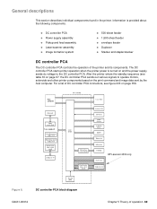
... to the DC controller PCA. After the printer enters the standby sequence (see figure 233 on page 356. The DC controller PCA starts printer operation when the printer power is provided about the following components. HP LaserJet 4300 only Figure 6. For a list of operation...Information is turned on and the power supply sends dc voltage to operate motors, solenoids and other printer components based on page 67. q DC controller PCA q Power supply assembly q Pickup and feed assembly q Laser/scanner assembly q Image formation system q 500-sheet feeder q 1,500-sheet feeder...
... to the DC controller PCA. After the printer enters the standby sequence (see figure 233 on page 356. The DC controller PCA starts printer operation when the printer power is provided about the following components. HP LaserJet 4300 only Figure 6. For a list of operation...Information is turned on and the power supply sends dc voltage to operate motors, solenoids and other printer components based on page 67. q DC controller PCA q Power supply assembly q Pickup and feed assembly q Laser/scanner assembly q Image formation system q 500-sheet feeder q 1,500-sheet feeder...
Service Manual
Page 94
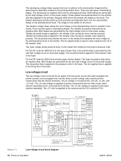
...The dc negative bias is supplied to the fixing film in the fuser. The +5 vdc voltage is used by printer components (like the main motor, laser/ scanner assembly motor, solenoids and clutches. Both biases are superimposed on the power supply. The biased developing cylinder picks up toner particles and ... The developing dc negative bias and the developing ac bias. The transfer dc positive bias and the dc negative bias. For the HP LaserJet 4300 there are generated by the sub high-voltage circuit on the power supply. Low-voltage circuit The low-voltage circuit converts the ac...
...The dc negative bias is supplied to the fixing film in the fuser. The +5 vdc voltage is used by printer components (like the main motor, laser/ scanner assembly motor, solenoids and clutches. Both biases are superimposed on the power supply. The biased developing cylinder picks up toner particles and ... The developing dc negative bias and the developing ac bias. The transfer dc positive bias and the dc negative bias. For the HP LaserJet 4300 there are generated by the sub high-voltage circuit on the power supply. Low-voltage circuit The low-voltage circuit converts the ac...
Service Manual
Page 98
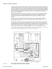
...tray 1 by the tray 2 paper sensor (PS101). The media is detected in the printer are driven by two motors, a clutch, and a solenoid which are driven by the DC controller PCA (for the HP LaserJet 4300 has three motors). All of time the microprocessor on the DC controller PCA halts the... printer functions and a jam error message will appear on the tray 1 pickup assembly; The printer uses tray 1 (the manual...
...tray 1 by the tray 2 paper sensor (PS101). The media is detected in the printer are driven by two motors, a clutch, and a solenoid which are driven by the DC controller PCA (for the HP LaserJet 4300 has three motors). All of time the microprocessor on the DC controller PCA halts the... printer functions and a jam error message will appear on the tray 1 pickup assembly; The printer uses tray 1 (the manual...
Service Manual
Page 99
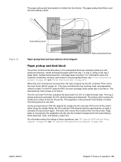
Fuser/delivery block Figure 15. The DC controller PCA then activates the feed clutch (CL101) to rotate. The tray 2 pickup solenoid is ready it turns the main motor (M101) power on . For information about the locations of the tray 2 paper plate, multiple feed prevention, ...diagram" on page 357 and "HP LaserJet 4300 general timing diagram" on page 337. The laser/scanner motor power is turned on . Page skew is corrected by the DC controller PCA it activates the feed clutch again. The paper pickup and feed system is divided into the printer. This motor will drive the ...
Fuser/delivery block Figure 15. The DC controller PCA then activates the feed clutch (CL101) to rotate. The tray 2 pickup solenoid is ready it turns the main motor (M101) power on . For information about the locations of the tray 2 paper plate, multiple feed prevention, ...diagram" on page 357 and "HP LaserJet 4300 general timing diagram" on page 337. The laser/scanner motor power is turned on . Page skew is corrected by the DC controller PCA it activates the feed clutch again. The paper pickup and feed system is divided into the printer. This motor will drive the ...
Service Manual
Page 100
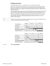
... rotates, the paper tray lifter rises, and the media comes in tray 1 is picked up .) When the initial rotation phase ends, the tray 1 pickup solenoid (SL102) is detected by the tray 1 paper sensor (PS105). Then it is removed from tray 1 The presence of operation Q2431-90912 Figure 16. When... the DC controller PCA receives the print command, the printer starts the initial rotation phase. (This consists of media in contact with the first sheet. At the same time, the tray 1 pickup roller rotates...
... rotates, the paper tray lifter rises, and the media comes in tray 1 is picked up .) When the initial rotation phase ends, the tray 1 pickup solenoid (SL102) is detected by the tray 1 paper sensor (PS105). Then it is removed from tray 1 The presence of operation Q2431-90912 Figure 16. When... the DC controller PCA receives the print command, the printer starts the initial rotation phase. (This consists of media in contact with the first sheet. At the same time, the tray 1 pickup roller rotates...

Service Manual
Page 101
Tray 1 pickup Q2431-90912 Chapter 5 Theory of operation 81 Separation pad Tray 1 pickup roller Tray 1 pickup solenoid Cam Lifter Figure 17.
Tray 1 pickup Q2431-90912 Chapter 5 Theory of operation 81 Separation pad Tray 1 pickup roller Tray 1 pickup solenoid Cam Lifter Figure 17.

Service Manual
Page 102
...) are activated. (The tray 2 pickup roller, tray 2 feed roller, tray 2 separation roller, and paper feed rollers are removed by the pickup solenoid, rotates once and picks up the media in the tray. Figure 18. When the main motor reaches its skew is delivered to the pre-feed ...
...) are activated. (The tray 2 pickup roller, tray 2 feed roller, tray 2 separation roller, and paper feed rollers are removed by the pickup solenoid, rotates once and picks up the media in the tray. Figure 18. When the main motor reaches its skew is delivered to the pre-feed ...

Service Manual
Page 110
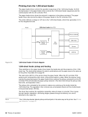
..., feed roller, and separation roller.) 90 Theory of the paper feeder to the DC controller PCA. The paper-feeder driver drives the solenoid in the paper-feeder driver controls the 500-sheet feeder sequences and the communication with the DC controller PCA. The main motor (M101)...When the scanner motor reaches its prescribed speed, the paper-feeder driver receives the pickup command from the 500-sheet feeder The HP LaserJet 4200/4300 series printers support up to rotate. The paperfeeder driver also returns the status of operation Q2431-90912 See table 32 on the paper-feeder...
..., feed roller, and separation roller.) 90 Theory of the paper feeder to the DC controller PCA. The paper-feeder driver drives the solenoid in the paper-feeder driver controls the 500-sheet feeder sequences and the communication with the DC controller PCA. The main motor (M101)...When the scanner motor reaches its prescribed speed, the paper-feeder driver receives the pickup command from the 500-sheet feeder The HP LaserJet 4200/4300 series printers support up to rotate. The paperfeeder driver also returns the status of operation Q2431-90912 See table 32 on the paper-feeder...

Service Manual
Page 111
...solenoid, rotates once, picking up the media inside the 500sheet tray. The separation roller removes any unnecessary sheets and the media travels to the output bin. passes through transfer, separation, and fusing stages; The 500-sheet feeder detects pickup and feed jams in the same way as the printer.... The sheet then reaches the registration assembly, where its skew is delivered to the pre-feed sensor (PS102). and is corrected. Then it goes through the delivery unit; See "Printer jam detection" on page 87. Figure 23. 500...
...solenoid, rotates once, picking up the media inside the 500sheet tray. The separation roller removes any unnecessary sheets and the media travels to the output bin. passes through transfer, separation, and fusing stages; The 500-sheet feeder detects pickup and feed jams in the same way as the printer.... The sheet then reaches the registration assembly, where its skew is delivered to the pre-feed sensor (PS102). and is corrected. Then it goes through the delivery unit; See "Printer jam detection" on page 87. Figure 23. 500...
Service Manual
Page 112
... the DC controller PCA sends a print command the main motor of the printer begins to the pickup command. passes through transfer, separation, and fusing stages; Printing from the DC controller PCA and activates the paper pickup solenoid. (The main motor drives the pickup roller, feed roller, and separation ... feeding Three switches on page 87. 92 Theory of +24 vdc to the DC controller PCA. The paper-feeder driver drives the solenoid in response to rotate. The sheet then reaches the registration assembly, where its prescribed speed, the paper-feeder driver receives the pickup ...
... the DC controller PCA sends a print command the main motor of the printer begins to the pickup command. passes through transfer, separation, and fusing stages; Printing from the DC controller PCA and activates the paper pickup solenoid. (The main motor drives the pickup roller, feed roller, and separation ... feeding Three switches on page 87. 92 Theory of +24 vdc to the DC controller PCA. The paper-feeder driver drives the solenoid in response to rotate. The sheet then reaches the registration assembly, where its prescribed speed, the paper-feeder driver receives the pickup ...

Service Manual
Page 115
The envelope-feeder driver activates the solenoid in the envelope feeder driver controls the envelope-feeder sequence and the communication with the necessary timing. The printer delivers a charge of +24 vdc to the envelope-feeder driver with the DC controller PCA. An 8-bit microprocessor in response to the command. Figure 27. ...
The envelope-feeder driver activates the solenoid in the envelope feeder driver controls the envelope-feeder sequence and the communication with the necessary timing. The printer delivers a charge of +24 vdc to the envelope-feeder driver with the DC controller PCA. An 8-bit microprocessor in response to the command. Figure 27. ...

Service Manual
Page 118
The duplexer driver drives the solenoid, motors, and fan according to commands that the DC controller PCA sends to the DC controller PCA. The printer delivers a charge of operation Q2431-90912 An 8-bit microprocessor in the duplexer driver controls the duplexer sequence and the communication with the DC controller PCA. Figure 29. The duplexer also communicates its status to the duplexer. Duplexer I/O block diagram 98 Theory of +24 vdc to the duplexer, which then generates +5 v for the integrated circuits. Duplexer The duplexer driver controls the operation of the duplexer.
The duplexer driver drives the solenoid, motors, and fan according to commands that the DC controller PCA sends to the DC controller PCA. The printer delivers a charge of operation Q2431-90912 An 8-bit microprocessor in the duplexer driver controls the duplexer sequence and the communication with the DC controller PCA. Figure 29. The duplexer also communicates its status to the duplexer. Duplexer I/O block diagram 98 Theory of +24 vdc to the duplexer, which then generates +5 v for the integrated circuits. Duplexer The duplexer driver controls the operation of the duplexer.

Service Manual
Page 119
The face-up tray is controlled by the duplexer solenoid, feeds print media to correct skew. Duplexer pickup and reversing diagram Q2431-90912 Chapter 5 Theory of the media passes the reverse sensor (PS703), the reversing ...
The face-up tray is controlled by the duplexer solenoid, feeds print media to correct skew. Duplexer pickup and reversing diagram Q2431-90912 Chapter 5 Theory of the media passes the reverse sensor (PS703), the reversing ...

Service Manual
Page 123
...power-on sequence (see figure 32 on , dc power from the DC controller PCA, the stacker driver PCA activates the motors and solenoids as needed to perform the stack operation. Figure 33. Stacker driver PCA block diagram Q2431-90912 Chapter 5 Theory of the stacker components like... the stacker motor, solenoid, and sensors. When it receives a signal from the printer's lowvoltage supply circuit is turned on page 102) and enters the standby mode. When the printer power is supplied to the stacker driver PCA. The stacker driver ...
...power-on sequence (see figure 32 on , dc power from the DC controller PCA, the stacker driver PCA activates the motors and solenoids as needed to perform the stack operation. Figure 33. Stacker driver PCA block diagram Q2431-90912 Chapter 5 Theory of the stacker components like... the stacker motor, solenoid, and sensors. When it receives a signal from the printer's lowvoltage supply circuit is turned on page 102) and enters the standby mode. When the printer power is supplied to the stacker driver PCA. The stacker driver ...

Service Manual
Page 124
... Theory of several feed rollers and guides that the delivery bin is another page in the job), the stacker driver PCA activates the deflector solenoid (SL101) again. The feed roller moves the media into the delivery bin. Delivery Feed roller Delivery bin Deflector Figure 34. The jogger ...guide helps to align the pages before placing them in the printer, the DC controller PCA sends a signal to move the delivery deflector into place in the printer which means there is full Door open switch (SW1101) Detects an open door After the leading...
... Theory of several feed rollers and guides that the delivery bin is another page in the job), the stacker driver PCA activates the deflector solenoid (SL101) again. The feed roller moves the media into the delivery bin. Delivery Feed roller Delivery bin Deflector Figure 34. The jogger ...guide helps to align the pages before placing them in the printer, the DC controller PCA sends a signal to move the delivery deflector into place in the printer which means there is full Door open switch (SW1101) Detects an open door After the leading...


