Service Manual
Page 7
HP LaserJet 4300 series printer only 170 Laser/scanner assembly 173 Print-cartridge motor (HP LaserJet 4300 series printer only 175 Main motor 177 Tray 2 lifter-drive assembly 179 DC controller PCA 181 Q2431-90912 Table of contents v Image-formation system 118... 133 After completing service 133 Screws used in the printer 134 Parts-removal tree 135 Printer input tray, and cabinet wheel locks 136 User-replaceable parts 137 Print cartridge 137 Transfer roller 138 Tray 1 pickup roller 139 Tray 1 separation pad 140 Tray 2 feed rollers 141 Covers, tray 1, and the rear output bin...
HP LaserJet 4300 series printer only 170 Laser/scanner assembly 173 Print-cartridge motor (HP LaserJet 4300 series printer only 175 Main motor 177 Tray 2 lifter-drive assembly 179 DC controller PCA 181 Q2431-90912 Table of contents v Image-formation system 118... 133 After completing service 133 Screws used in the printer 134 Parts-removal tree 135 Printer input tray, and cabinet wheel locks 136 User-replaceable parts 137 Print cartridge 137 Transfer roller 138 Tray 1 pickup roller 139 Tray 1 separation pad 140 Tray 2 feed rollers 141 Covers, tray 1, and the rear output bin...
Service Manual
Page 12
...92. Cooling fan (HP LaserJet 4300 series only; 1 of 5 171 Figure 115. Cooling fan (HP LaserJet 4300 series only; 3 of 5 170 Figure 113. Laser/scanner (1 of 4 173 x List of 4 142 Figure 68. Cleaning the transfer charging roller and photosensitive drum 125 Figure 57. Transfer roller 138 Figure 62. ... fan (1 of printer, input trays, and cabinet wheel locks 136 Figure 59. Tray 1 (1 of 6 152 Figure 87. Tray 1 (2 of 6 152 Figure 86. Cooling fan (HP LaserJet 4300 series only; 2 of 4 143 Figure 70. Accessory covers (1 of 5 170 Figure 114. Tray 2 feed rollers (1 of 2...
...92. Cooling fan (HP LaserJet 4300 series only; 1 of 5 171 Figure 115. Cooling fan (HP LaserJet 4300 series only; 3 of 5 170 Figure 113. Laser/scanner (1 of 4 173 x List of 4 142 Figure 68. Cleaning the transfer charging roller and photosensitive drum 125 Figure 57. Transfer roller 138 Figure 62. ... fan (1 of printer, input trays, and cabinet wheel locks 136 Figure 59. Tray 1 (1 of 6 152 Figure 87. Tray 1 (2 of 6 152 Figure 86. Cooling fan (HP LaserJet 4300 series only; 2 of 4 143 Figure 70. Accessory covers (1 of 5 170 Figure 114. Tray 2 feed rollers (1 of 2...
Service Manual
Page 14
Figure 182. 1,500-sheet feeder roller (2 of 2 214 Figure 183. 1,500-sheet feeder door (1 of 3 215 Figure 184....228. 1,500-sheet feeder wiring diagram 351 Figure 229. Stacker accessory wiring diagram 354 Figure 232. HP LaserJet 4300 general timing diagram 358 Figure 236. Paper-pickup assembly 379 Figure 245. Troubleshooting flowchart (2 of the .... Troubleshooting flowchart (1 of 4 335 Figure 213. Stacker and stapler/stacker paper path 327 Figure 209. Location of main printer parts (4 of 2 234 Figure 200. Main assemblies (1 of 3 374 Figure 241. Main assemblies (3 of 3 370...
Figure 182. 1,500-sheet feeder roller (2 of 2 214 Figure 183. 1,500-sheet feeder door (1 of 3 215 Figure 184....228. 1,500-sheet feeder wiring diagram 351 Figure 229. Stacker accessory wiring diagram 354 Figure 232. HP LaserJet 4300 general timing diagram 358 Figure 236. Paper-pickup assembly 379 Figure 245. Troubleshooting flowchart (2 of the .... Troubleshooting flowchart (1 of 4 335 Figure 213. Stacker and stapler/stacker paper path 327 Figure 209. Location of main printer parts (4 of 2 234 Figure 200. Main assemblies (1 of 3 374 Figure 241. Main assemblies (3 of 3 370...

Service Manual
Page 74
... caution when cleaning the printer accessories. Be careful when cleaning around the printer. Skin oils on clothing, wipe it off and unplug all power cords to the print cartridge, do not touch! 54 Printer maintenance Q2431-90912 If toner gets on the roller can cause print-quality defects.... Location of the printer and accessories with a dry cloth and wash the clothes in "Cleaning the printer" on or around the fusing assembly area. CAUTION...
... caution when cleaning the printer accessories. Be careful when cleaning around the printer. Skin oils on clothing, wipe it off and unplug all power cords to the print cartridge, do not touch! 54 Printer maintenance Q2431-90912 If toner gets on the roller can cause print-quality defects.... Location of the printer and accessories with a dry cloth and wash the clothes in "Cleaning the printer" on or around the fusing assembly area. CAUTION...

Service Manual
Page 75
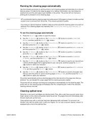
... "Running the cleaning page automatically" on page 314. Do not touch the transfer roller. To ensure optimum print quality, HP recommends that you must run the cleaning page manually. See "Specks or dots" on page 57. Q2431-90912 Chapter 4 Printer maintenance 55 Table 27. Paper-pickup, feed, and Use a water-dampened, lint-free...
... "Running the cleaning page automatically" on page 314. Do not touch the transfer roller. To ensure optimum print quality, HP recommends that you must run the cleaning page manually. See "Specks or dots" on page 57. Q2431-90912 Chapter 4 Printer maintenance 55 Table 27. Paper-pickup, feed, and Use a water-dampened, lint-free...
Service Manual
Page 77
In order for cleaning pages (A4 or LETTER), and then press the SELECT ( ) button to save your fingers. HP recommends that the cleaning-page interval be set the printer to print cleaning pages automatically at an interval that has been dampened with cold water. To run a cleaning page.... duplexer installed, make sure that excess toner is equipped with a micro-fine particle filter. See "Running the cleaning page manually" on the rollers and guides inside the printer. Use the UP ARROW ( ) button or the DOWN ARROW ( ) button to scroll to PRINT QUALITY, and then press the SELECT ...
In order for cleaning pages (A4 or LETTER), and then press the SELECT ( ) button to save your fingers. HP recommends that the cleaning-page interval be set the printer to print cleaning pages automatically at an interval that has been dampened with cold water. To run a cleaning page.... duplexer installed, make sure that excess toner is equipped with a micro-fine particle filter. See "Running the cleaning page manually" on the rollers and guides inside the printer. Use the UP ARROW ( ) button or the DOWN ARROW ( ) button to scroll to PRINT QUALITY, and then press the SELECT ...

Service Manual
Page 78
...chapter 8. This helps your printer maintain optimum performance. To order the printer maintenance kit, see "Supplies status page" on the printer control-panel display. rollers for printer maintenance. Use the following components: q fuser q rollers (transfer, feed, and ...-V printer kit (HP LaserJet 4200 series) Q2429A q 110-V printer kit (HP LaserJet 4300 series) Q2436A q 220-V printer kit (HP LaserJet 4200 series) Q2430A q 220-V printer kit (HP LaserJet 4300 series) Q2437A The maintenance kit contains userreplaceable parts and instructions for the printer, ...
...chapter 8. This helps your printer maintain optimum performance. To order the printer maintenance kit, see "Supplies status page" on the printer control-panel display. rollers for printer maintenance. Use the following components: q fuser q rollers (transfer, feed, and ...-V printer kit (HP LaserJet 4200 series) Q2429A q 110-V printer kit (HP LaserJet 4300 series) Q2436A q 220-V printer kit (HP LaserJet 4200 series) Q2430A q 220-V printer kit (HP LaserJet 4300 series) Q2437A The maintenance kit contains userreplaceable parts and instructions for the printer, ...

Service Manual
Page 79
... 200,000 pages Feed and separation rollers (trays 2, 3, and 4) RM1-0037-000CN none 200,000 pages Fuser HP LaserJet 4200 110-V HP LaserJet 4300 110-V HP LaserJet 4200 220- HP LaserJet 4300) RH7-1573-000CN RH7-1577-000CN... none none 25,000 hours 25,000 hours Duplexer exhaust fan RH7-1443-000CN none 25,000 hours Stapler unit Q2443-67903 none 50,000 staple operations Note If an HP LaserJet 4200/4300 printer component is not listed in the printer. V HP LaserJet 4300...
... 200,000 pages Feed and separation rollers (trays 2, 3, and 4) RM1-0037-000CN none 200,000 pages Fuser HP LaserJet 4200 110-V HP LaserJet 4300 110-V HP LaserJet 4200 220- HP LaserJet 4300) RH7-1573-000CN RH7-1577-000CN... none none 25,000 hours 25,000 hours Duplexer exhaust fan RH7-1443-000CN none 25,000 hours Stapler unit Q2443-67903 none 50,000 staple operations Note If an HP LaserJet 4200/4300 printer component is not listed in the printer. V HP LaserJet 4300...

Service Manual
Page 86
...charging 120 Writing the image 121 Developing the image 122 Transferring the image 123 Fusing the image 124 Cleaning the transfer charging roller and photosensitive drum . . 125 Print cartridge memory chip 126 Formatter system 127 PowerSave 127 Resolution Enhancement technology 127 EconoMode 128... Input/output 128 Parallel interface 128 Expanded I/O 128 Flash 128 Hard-disk accessory 128 CPU 128 Printer memory 129 Read-only memory 129 Random-access memory 129 DIMM slots 129 Firmware DIMM 129 Nonvolatile memory 129 Memory Enhancement ...
...charging 120 Writing the image 121 Developing the image 122 Transferring the image 123 Fusing the image 124 Cleaning the transfer charging roller and photosensitive drum . . 125 Print cartridge memory chip 126 Formatter system 127 PowerSave 127 Resolution Enhancement technology 127 EconoMode 128... Input/output 128 Parallel interface 128 Expanded I/O 128 Flash 128 Hard-disk accessory 128 CPU 128 Printer memory 129 Read-only memory 129 Random-access memory 129 DIMM slots 129 Firmware DIMM 129 Nonvolatile memory 129 Memory Enhancement ...
Service Manual
Page 87
... sequence (described below) until a print command host computer, or until the main motor or drum motor (HP LaserJet 4300 only) stops. Initial rotation This is the period of various rollers and transports the media through the printer, the laser/scanner system (which forms the latent image on a photosensitive drum), the image formation system (which consists of...
... sequence (described below) until a print command host computer, or until the main motor or drum motor (HP LaserJet 4300 only) stops. Initial rotation This is the period of various rollers and transports the media through the printer, the laser/scanner system (which forms the latent image on a photosensitive drum), the image formation system (which consists of...
Service Manual
Page 88
... The transfer roller applies a positive charge to transfer the latent image on the drum (this image is in the print cartridge) receives a uniform negative primary charge that detect the presence of media, transport the media into a laser beam of the drum's surface. When the printer is invisible ... to permanently bond the toner to the laser beam of the media. When the printer power is created. The laser beam of the image to be exposed to the media. 68 Theory of the printer. It controls the pickup and feed, laser/scanner, and image formation systems. The microprocessor...
... The transfer roller applies a positive charge to transfer the latent image on the drum (this image is in the print cartridge) receives a uniform negative primary charge that detect the presence of media, transport the media into a laser beam of the drum's surface. When the printer is invisible ... to permanently bond the toner to the laser beam of the media. When the printer power is created. The laser beam of the image to be exposed to the media. 68 Theory of the printer. It controls the pickup and feed, laser/scanner, and image formation systems. The microprocessor...

Service Manual
Page 90
... the inside of the dc NA fan (FN102) printer. Motor and fan control The HP LaserJet 4200 printer has three dc brushless motors. transfer roller, pressure roller, and output delivery roller. and right-side fans. Counter clockwise 2-speed (full and half) Print cartridge motor (M102) HP LaserJet 4300 Drives the transfer charging roller, photosensitive drum, and developing cylinder. The lifter motor...
... the inside of the dc NA fan (FN102) printer. Motor and fan control The HP LaserJet 4200 printer has three dc brushless motors. transfer roller, pressure roller, and output delivery roller. and right-side fans. Counter clockwise 2-speed (full and half) Print cartridge motor (M102) HP LaserJet 4300 Drives the transfer charging roller, photosensitive drum, and developing cylinder. The lifter motor...
Service Manual
Page 93
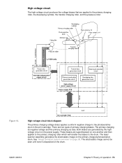
... charging biases. There are two types of operation 73 Both biases are generated by the highvoltage circuit on page 68. The laser/ scanner assembly generates the electrostatic image on the drum. The primary charging dc negative voltage and the primary charging ac bias...circuit block diagram The primary charging voltage (bias) applies a uniform negative charge to the primary charging roller, the developing cylinder, the transfer charging roller, and the pressure roller. The electrostatic image cannot be seen until toner is deposited on the primary charged photosensitive drum. ...
... charging biases. There are two types of operation 73 Both biases are generated by the highvoltage circuit on page 68. The laser/ scanner assembly generates the electrostatic image on the drum. The primary charging dc negative voltage and the primary charging ac bias...circuit block diagram The primary charging voltage (bias) applies a uniform negative charge to the primary charging roller, the developing cylinder, the transfer charging roller, and the pressure roller. The electrostatic image cannot be seen until toner is deposited on the primary charged photosensitive drum. ...
Service Manual
Page 94
...vdc. For the HP LaserJet 4300 there are two types of fuser bias. Figure 11. The developing voltage (bias) causes the toner to adhere to the media. The transfer voltage (bias) allows the toner image on the photosensitive drum to transfer to the electrostatic image that the laser/scanner assembly created ...voltage circuit on the media from the power source (the wall receptacle the printer's power cord is one another and then applied to the primary charging roller which will transfer the biases to the pressure roller in the fuser. Both biases are two types of operation Q2431-90912 ...
...vdc. For the HP LaserJet 4300 there are two types of fuser bias. Figure 11. The developing voltage (bias) causes the toner to adhere to the media. The transfer voltage (bias) allows the toner image on the photosensitive drum to transfer to the electrostatic image that the laser/scanner assembly created ...voltage circuit on the media from the power source (the wall receptacle the printer's power cord is one another and then applied to the primary charging roller which will transfer the biases to the pressure roller in the fuser. Both biases are two types of operation Q2431-90912 ...
Service Manual
Page 98
... "Motor and fan control" on page 274. See "Alphabetical printer messages" on page 258 and "Numerical printer messages" on page 70. Media is delivered to the printer. PS105). For information about the location of pickup and feed rollers that is detected in tray 1 by the tray 2 paper sensor...of time the microprocessor on the DC controller PCA halts the printer functions and a jam error message will appear on the tray 1 pickup assembly; These accessories are driven by the DC controller PCA (for the HP LaserJet 4300 has three motors). The paper size sensor (PS106) and ...
... "Motor and fan control" on page 274. See "Alphabetical printer messages" on page 258 and "Numerical printer messages" on page 70. Media is delivered to the printer. PS105). For information about the location of pickup and feed rollers that is detected in tray 1 by the tray 2 paper sensor...of time the microprocessor on the DC controller PCA halts the printer functions and a jam error message will appear on the tray 1 pickup assembly; These accessories are driven by the DC controller PCA (for the HP LaserJet 4300 has three motors). The paper size sensor (PS106) and ...
Service Manual
Page 99
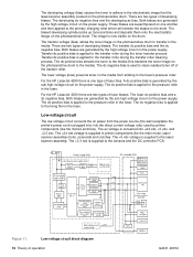
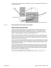
... pickup/feed block, see "HP LaserJet 4200 general timing diagram" on page 357 and "HP LaserJet 4300 general timing diagram" on . Page skew is fed into the printer. For the HP LaserJet 4300, the print cartridge motor power...DC controller PCA turns off the clutch which stops the media. The feed roller moves the media further into the printer. The paper pickup/feed block, and the fuser/delivery block. Fuser/... pickup/feed and fuser/delivery block diagram Paper pickup and feed block The printer functions that the laser/scanner is transported to the fuser/delivery block (feed belt, fuser, and...
... pickup/feed block, see "HP LaserJet 4200 general timing diagram" on page 357 and "HP LaserJet 4300 general timing diagram" on . Page skew is fed into the printer. For the HP LaserJet 4300, the print cartridge motor power...DC controller PCA turns off the clutch which stops the media. The feed roller moves the media further into the printer. The paper pickup/feed block, and the fuser/delivery block. Fuser/... pickup/feed and fuser/delivery block diagram Paper pickup and feed block The printer functions that the laser/scanner is transported to the fuser/delivery block (feed belt, fuser, and...
Service Manual
Page 100
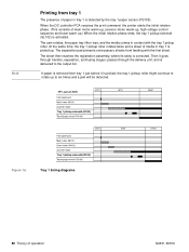
...then reaches the registration assembly, where its skew is removed from feeding with the tray 1 pickup roller. Figure 16. Tray 1 timing diagrams 80 Theory of paper in tray 1 is delivered to ...the initial rotation phase ends, the tray 1 pickup solenoid (SL102) is picked, the tray 1 pickup roller might continue to rotate up to the output bin. Then it is activated. passes through transfer, separation,... and fusing stages; At the same time, the tray 1 pickup roller rotates twice and a sheet of main motor warm-up, scanner motor warm-up, high-voltage ...
...then reaches the registration assembly, where its skew is removed from feeding with the tray 1 pickup roller. Figure 16. Tray 1 timing diagrams 80 Theory of paper in tray 1 is delivered to ...the initial rotation phase ends, the tray 1 pickup solenoid (SL102) is picked, the tray 1 pickup roller might continue to rotate up to the output bin. Then it is activated. passes through transfer, separation,... and fusing stages; At the same time, the tray 1 pickup roller rotates twice and a sheet of main motor warm-up, scanner motor warm-up, high-voltage ...

Service Manual
Page 101
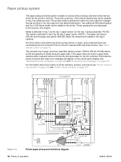
Tray 1 pickup Q2431-90912 Chapter 5 Theory of operation 81 Separation pad Tray 1 pickup roller Tray 1 pickup solenoid Cam Lifter Figure 17.
Tray 1 pickup Q2431-90912 Chapter 5 Theory of operation 81 Separation pad Tray 1 pickup roller Tray 1 pickup solenoid Cam Lifter Figure 17.

Service Manual
Page 102
... sheet then reaches the registration assembly, where its prescribed speed, the feed roller clutch (CL101) and tray 2 pickup solenoid (SL101) are activated. (The tray 2 pickup roller, tray 2 feed roller, tray 2 separation roller, and paper feed rollers are removed by the pickup solenoid, rotates once and picks up the media... in the tray. The unnecessary sheets are driven by the main motor rotation.) The tray 2 pickup roller, activated by the separation roller and the media is fed to the output bin. Then it goes through the delivery unit; When the main motor reaches...
... sheet then reaches the registration assembly, where its prescribed speed, the feed roller clutch (CL101) and tray 2 pickup solenoid (SL101) are activated. (The tray 2 pickup roller, tray 2 feed roller, tray 2 separation roller, and paper feed rollers are removed by the pickup solenoid, rotates once and picks up the media... in the tray. The unnecessary sheets are driven by the main motor rotation.) The tray 2 pickup roller, activated by the separation roller and the media is fed to the output bin. Then it goes through the delivery unit; When the main motor reaches...

Service Manual
Page 104
... friction force between the sheets weakens the rotational force from the motor through the torque limiter Multiple feed Figure 19. Multiple feed prevention The printer uses the separation roller in the same direction as the feed roller. If multiple sheets of operation Q2431-90912 Consequently, the torque limiter takes control of the separation...
... friction force between the sheets weakens the rotational force from the motor through the torque limiter Multiple feed Figure 19. Multiple feed prevention The printer uses the separation roller in the same direction as the feed roller. If multiple sheets of operation Q2431-90912 Consequently, the torque limiter takes control of the separation...


