

Product Manual
Page 2
Contents Safety and warnings 2-3 Introduction 4 Installation 5-11 Remote Control 12 Operation...13-17 Trouble Shooting 18 Warranty...19 -1-
Contents Safety and warnings 2-3 Introduction 4 Installation 5-11 Remote Control 12 Operation...13-17 Trouble Shooting 18 Warranty...19 -1-
Product Manual
Page 3
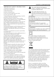
... readily operable. 15) The ventilation should not be impeded by the manufacturer. 12) Unplug this apparatus during lighting storms or when unused for long periods of time. 13) Refer all instructions. 5) Do not use this apparatus near any heat sources such as power-supply cord or plug is ...18) The use only identical replacement parts. CAUTION RISK OF ELECTRIC SHOCK DO NOT OPEN! CAUTION TO REDUCE THE RISK OF ELECTRIC SHOCK, DO NOT REMOVE COVER (OR BACK).NO USER SERVICEABLE PARTS INSIDE. The symbol indicates that no objects filled with the instructions. 8) Do not install near water....
... readily operable. 15) The ventilation should not be impeded by the manufacturer. 12) Unplug this apparatus during lighting storms or when unused for long periods of time. 13) Refer all instructions. 5) Do not use this apparatus near any heat sources such as power-supply cord or plug is ...18) The use only identical replacement parts. CAUTION RISK OF ELECTRIC SHOCK DO NOT OPEN! CAUTION TO REDUCE THE RISK OF ELECTRIC SHOCK, DO NOT REMOVE COVER (OR BACK).NO USER SERVICEABLE PARTS INSIDE. The symbol indicates that no objects filled with the instructions. 8) Do not install near water....
Product Manual
Page 4
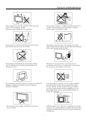
... the AC outlet. Never spill any kind of liquid on other sources of heat. When the television receiver is not used in the operation of this television receiver. SAFETY AND WARNINGS High voltages are used for an extended period of time, it is advisable to be built into the television cabinet slots or openings. Do not trap the power supply cord under the television receiver's stand.
... the AC outlet. Never spill any kind of liquid on other sources of heat. When the television receiver is not used in the operation of this television receiver. SAFETY AND WARNINGS High voltages are used for an extended period of time, it is advisable to be built into the television cabinet slots or openings. Do not trap the power supply cord under the television receiver's stand.
Product Manual
Page 5
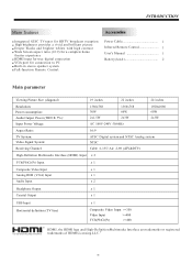
... theater experience HDMI input for true digital connection VGA port for connection to PC Built-in stereo speaker system Full-function Remote Control Power Cable 1 Infrared Remote Control 1 User s Manual 1 Battery(AAA 2 Main parameter Viewing Picture Size (diagonal) 19 inches 22 inches 24 inches Resolution: Power consumption: Audio Output Power (THD 7%): Input Power Voltage: 1366x768 30W 1366x768 60W 2x1.5W 2x3W AC 100V-240V 50/60Hz 1920x1080 60W 2x3W Aspect Ratio: 16:9 TV System: Video Signal System: Receiving Channel: ATSC Digital system and...
... theater experience HDMI input for true digital connection VGA port for connection to PC Built-in stereo speaker system Full-function Remote Control Power Cable 1 Infrared Remote Control 1 User s Manual 1 Battery(AAA 2 Main parameter Viewing Picture Size (diagonal) 19 inches 22 inches 24 inches Resolution: Power consumption: Audio Output Power (THD 7%): Input Power Voltage: 1366x768 30W 1366x768 60W 2x1.5W 2x3W AC 100V-240V 50/60Hz 1920x1080 60W 2x3W Aspect Ratio: 16:9 TV System: Video Signal System: Receiving Channel: ATSC Digital system and...
Product Manual
Page 6
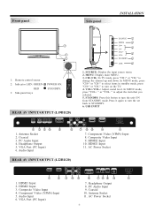
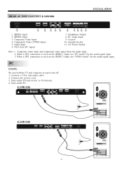
In MENU mode, press "VOL+ " or "VOL- STANDBY: Press this button to adjust the item that you selected. 5. VGA Port (PC Input) 6. HDMI1 Input 11. Component Video (YPbPr) Input 5. Audio Input 6. Antenna Socket 11. AC INPUT 100-240V~50/60Hz 11 Front panel Side panel INSTALLATION SOURCE 1 MENU 2 3 CH+ CH- 3 VOL+ 1 4 VOL- 2 STANDBY 5 USB 6 30 30 1: Remote control sensor. 1 2 3 4 5 6 7 8 9 0 2: Indicator LED: GREEN POWER ON. VOL+/VOL-: Adjust sound level. " to turn on the TV. 4. Headphone Output 5. HDMI1 Input 2. Coaxial 10. RED STANDBY. +...
In MENU mode, press "VOL+ " or "VOL- STANDBY: Press this button to adjust the item that you selected. 5. VGA Port (PC Input) 6. HDMI1 Input 11. Component Video (YPbPr) Input 5. Audio Input 6. Antenna Socket 11. AC INPUT 100-240V~50/60Hz 11 Front panel Side panel INSTALLATION SOURCE 1 MENU 2 3 CH+ CH- 3 VOL+ 1 4 VOL- 2 STANDBY 5 USB 6 30 30 1: Remote control sensor. 1 2 3 4 5 6 7 8 9 0 2: Indicator LED: GREEN POWER ON. VOL+/VOL-: Adjust sound level. " to turn on the TV. 4. Headphone Output 5. HDMI1 Input 2. Coaxial 10. RED STANDBY. +...
Product Manual
Page 7
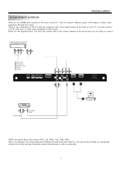
... switch to VGAmode. 4. Headphone Output 8. When a DVI connection is used on the HDMI 2 Input, use "PC Audio" for the audio signal input. Connect a VGA and audio cable. 2. Antenna Socket 11. Connect the power cord. 3. Coaxial 10. PC Audio Input 9. Turn on the PC. (L19B1120) RF INPUT COAXIAL PC AUDIO INPUT HEADPHONE VGA INPUT R Y AV COMPONENT INPUT L Pb Pr HDMI 2 HDMI 1 (L22B1120) HDMI 1 HDMI 2 Pr Pb L COMPONENT INPUT AUDIO INPUT AV Y R VGA INPUT HEADPHONE PC AUDIO INPUT COAXIAL RF INPUT AC INPUT 100-240V~50/60Hz -6- Composite video input...
... switch to VGAmode. 4. Headphone Output 8. When a DVI connection is used on the HDMI 2 Input, use "PC Audio" for the audio signal input. Connect a VGA and audio cable. 2. Antenna Socket 11. Connect the power cord. 3. Coaxial 10. PC Audio Input 9. Turn on the PC. (L19B1120) RF INPUT COAXIAL PC AUDIO INPUT HEADPHONE VGA INPUT R Y AV COMPONENT INPUT L Pb Pr HDMI 2 HDMI 1 (L22B1120) HDMI 1 HDMI 2 Pr Pb L COMPONENT INPUT AUDIO INPUT AV Y R VGA INPUT HEADPHONE PC AUDIO INPUT COAXIAL RF INPUT AC INPUT 100-240V~50/60Hz -6- Composite video input...

Product Manual
Page 9
Input impendance:75 unbalanced. -8- ANTENNA INSTALLATION Note: Aerial connections:IEC(female).
Input impendance:75 unbalanced. -8- ANTENNA INSTALLATION Note: Aerial connections:IEC(female).
Product Manual
Page 10
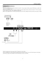
... player, DVD player, or other video equipment to these ports. Please see the diagram below. VIDEO EQUIPMENT with YPbPr GBR WR Y Yellow (video) W White(audio L) R Red(audio R or Pr) B Blue(Pb) G Green(Y) RF INPUT COAXIAL PC AUDIO INPUT HEADPHONE VGA INPUT WR GB R R Y AV COMPONENT INPUT HDMI 2 L Pb Pr W R HDMI 1 HDMI VIDEO EQUIPMENT W R TO VIDEO output To audio outputs There is one component (Y, Pb, Pr) and one composite (AV) video input located on the back of your TV. You may also need...
... player, DVD player, or other video equipment to these ports. Please see the diagram below. VIDEO EQUIPMENT with YPbPr GBR WR Y Yellow (video) W White(audio L) R Red(audio R or Pr) B Blue(Pb) G Green(Y) RF INPUT COAXIAL PC AUDIO INPUT HEADPHONE VGA INPUT WR GB R R Y AV COMPONENT INPUT HDMI 2 L Pb Pr W R HDMI 1 HDMI VIDEO EQUIPMENT W R TO VIDEO output To audio outputs There is one component (Y, Pb, Pr) and one composite (AV) video input located on the back of your TV. You may also need...
Product Manual
Page 11
... VIDEO output To audio outputs There is one component (Y, Pb, Pr) and one composite (AV) video input located on the side of the device that you are two HDMI ports located on the back of your TV. You may also need to refer to the owner's manual of the TV. You can connect a VCR, cable box, or other video equipment through these jacks. You can connect a Blu-ray player, DVD player, or...
... VIDEO output To audio outputs There is one component (Y, Pb, Pr) and one composite (AV) video input located on the side of the device that you are two HDMI ports located on the back of your TV. You may also need to refer to the owner's manual of the TV. You can connect a VCR, cable box, or other video equipment through these jacks. You can connect a Blu-ray player, DVD player, or...
Product Manual
Page 12
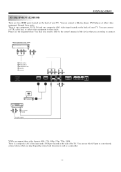
... the diagram below. You can connect a VCR, cable box, or other video equipment through these jacks. There is a composite (AV) video input and a USB port located on the back of the TV. VIDEO EQUIPMENT with YPbPr GBR WR Y Yellow (video) W White(audio L) R Red(audio R or Pr) B Blue(Pb) G Green(Y) AC INPUT 100-240V~50/60Hz HDMI 1 GB R WR HDMI 2 Pr Pb COMPONENT INPUT AUDIO L INPUT AV Y R VGA INPUT W R PC AUDIO HEADPHONE COAXIAL INPUT RF INPUT HDMI VIDEO EQUIPMENT W R TO VIDEO output To audio outputs...
... the diagram below. You can connect a VCR, cable box, or other video equipment through these jacks. There is a composite (AV) video input and a USB port located on the back of the TV. VIDEO EQUIPMENT with YPbPr GBR WR Y Yellow (video) W White(audio L) R Red(audio R or Pr) B Blue(Pb) G Green(Y) AC INPUT 100-240V~50/60Hz HDMI 1 GB R WR HDMI 2 Pr Pb COMPONENT INPUT AUDIO L INPUT AV Y R VGA INPUT W R PC AUDIO HEADPHONE COAXIAL INPUT RF INPUT HDMI VIDEO EQUIPMENT W R TO VIDEO output To audio outputs...
Product Manual
Page 13
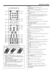
REMOTE CONTROL 1: POWER Press to power ON/OFF (standby) the TV. 2: NUMBER KEY Press to enter theTV channel numberand select a channel (Press " " tochoose the sub-channel). 3: MENU Press to open theon screen display (OSD)menu or return to switch audio modes: Standard, News, Music,Theater, Sports orCustom. 17: CH+/CHPress CH+ or CH- Remove the battery cover. 2. Replace with the Remote Control. to browse through theTV channels. 18: ASPECT Press to change thepicture...
REMOTE CONTROL 1: POWER Press to power ON/OFF (standby) the TV. 2: NUMBER KEY Press to enter theTV channel numberand select a channel (Press " " tochoose the sub-channel). 3: MENU Press to open theon screen display (OSD)menu or return to switch audio modes: Standard, News, Music,Theater, Sports orCustom. 17: CH+/CHPress CH+ or CH- Remove the battery cover. 2. Replace with the Remote Control. to browse through theTV channels. 18: ASPECT Press to change thepicture...
Product Manual
Page 14
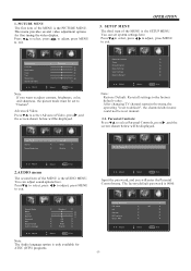
... be set system settings here. After changingTV channel namein the menu, the operating "reset to the factory default value. SETUP MENU The third item of the MENU is the AUDIO MENU. You can adjust sound options here. Adjust Select Menu Exit Input the password, and you want to adjust contrast, brightness, color, and sharpness, the picture mode must be displayed. This menu provides several video adjustment options for ATSC (DTV) programs. Change password P.G switch US Canada RRT setting Reset RRT Adjust > < Off > < > < > < > < > Select Menu Exit...
... be set system settings here. After changingTV channel namein the menu, the operating "reset to the factory default value. SETUP MENU The third item of the MENU is the AUDIO MENU. You can adjust sound options here. Adjust Select Menu Exit Input the password, and you want to adjust contrast, brightness, color, and sharpness, the picture mode must be displayed. This menu provides several video adjustment options for ATSC (DTV) programs. Change password P.G switch US Canada RRT setting Reset RRT Adjust > < Off > < > < > < > < > Select Menu Exit...
Product Manual
Page 15
... violence) situation) language) suggestive dialog) TV-Y (All children) TV-Y7(Direct to lock/unlock Parental Controls. 2). Restrict. TV MPAA > < N/A > Adjust Select Menu Exit 1): TV:Press , and the screen shown below will be displayed. OPERATION Change Password: Press , and the screen shown below will be displayed. Confirm password: Input the new password again P.G switch: When the Parental Control is unifiedwith NC-17 but maybe encoded in the dataof older movies...
... violence) situation) language) suggestive dialog) TV-Y (All children) TV-Y7(Direct to lock/unlock Parental Controls. 2). Restrict. TV MPAA > < N/A > Adjust Select Menu Exit 1): TV:Press , and the screen shown below will be displayed. OPERATION Change Password: Press , and the screen shown below will be displayed. Confirm password: Input the new password again P.G switch: When the Parental Control is unifiedwith NC-17 but maybe encoded in the dataof older movies...
Product Manual
Page 16
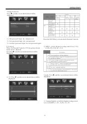
... they may be displayed. NO YES Press¡E°NTER¡K±ey To Select Adjust Select Menu Exit Mode Font style Font size Font Edge style Font Edge color FG color BG color FG opacity BG opacity Adjust Select Custom > Default > Default > Default > Default Default > Default > Default > Default > Menu Exit NOTE: Only available in a humorousor unrealistic manner . CC Mode Basic Selection Advanced Selection Option < Off > < CC1 > < Service 1 > > 18ans+ Over...
... they may be displayed. NO YES Press¡E°NTER¡K±ey To Select Adjust Select Menu Exit Mode Font style Font size Font Edge style Font Edge color FG color BG color FG opacity BG opacity Adjust Select Custom > Default > Default > Default > Default Default > Default > Default > Default > Menu Exit NOTE: Only available in a humorousor unrealistic manner . CC Mode Basic Selection Advanced Selection Option < Off > < CC1 > < Service 1 > > 18ans+ Over...
Product Manual
Page 17
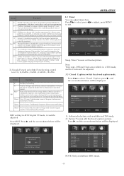
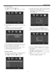
... screen. 3). Auto: Auto adjust to adjust this itemoption. 5). R F CH: 4 Found: 4 Analog: 1 Digital: 3 Adjust Select Menu Exit 3). Air/cable Auto Scan Favorite Show/Hide Channel NO. Usually you don't need to fit the screen. 4. Channel label: Press to adjust. Channel Lable. DTV signal: Adjust < < Select Air > > > > 2-1 > > Good Menu Exit -16- Press to select VGA Settings, press , and the screen shown below will be displayed, which indicates that the auto search is the Channel MENU. Air/Cable: Select Air TV signal...
... screen. 3). Auto: Auto adjust to adjust this itemoption. 5). R F CH: 4 Found: 4 Analog: 1 Digital: 3 Adjust Select Menu Exit 3). Air/cable Auto Scan Favorite Show/Hide Channel NO. Usually you don't need to fit the screen. 4. Channel label: Press to adjust. Channel Lable. DTV signal: Adjust < < Select Air > > > > 2-1 > > Good Menu Exit -16- Press to select VGA Settings, press , and the screen shown below will be displayed, which indicates that the auto search is the Channel MENU. Air/Cable: Select Air TV signal...

Product Manual
Page 18
... 20787.jpg 20087.jpg :17 Total size:3.7GB Unused size: 3.7 GB 001/018 1024 x 768 372.72KB 2006:07:14 15:37:42 Use select the. Select Music The screen shown below will be displayed. You can use the Multimedia Menu to the previous menu. : play : pause : stop playing or go to display JPEG pictures and play , press EXIT to go to the...
... 20787.jpg 20087.jpg :17 Total size:3.7GB Unused size: 3.7 GB 001/018 1024 x 768 372.72KB 2006:07:14 15:37:42 Use select the. Select Music The screen shown below will be displayed. You can use the Multimedia Menu to the previous menu. : play : pause : stop playing or go to display JPEG pictures and play , press EXIT to go to the...
Product Manual
Page 19
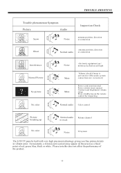
... color Noise Mute Mute electronic equipment,car/ motorcycle,fluorescent light Volume (check if mute is activated or if the audio system connections are not correct) Power cord is not inserted Power switch is not opened Contrast and brightness/volume setup Press standby key on the screen as a fixed point of the product. -18- Please note this does not affect the performance of red, green, blue, black or white...
... color Noise Mute Mute electronic equipment,car/ motorcycle,fluorescent light Volume (check if mute is activated or if the audio system connections are not correct) Power cord is not inserted Power switch is not opened Contrast and brightness/volume setup Press standby key on the screen as a fixed point of the product. -18- Please note this does not affect the performance of red, green, blue, black or white...

Energy Guide Label
Page 1
$4 Haier L22B1120 $8 $13 (21" - 23") use of this model: 77 kWh
$4 Haier L22B1120 $8 $13 (21" - 23") use of this model: 77 kWh


