Manual
Page 10
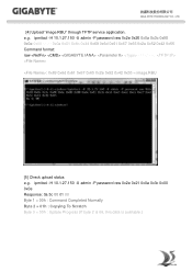
... upload status e.g. ipmitool -H 10.1.27.150 -U admin -P password raw 0x2e 0x21 0x0a 0x3c 0x00 0x0e Response: 0a 3c 00 01 00 Byte 1 = 00h : Command Completed Normally Byte 2 = 01h : Copying To Scratch Byte 3 = 00h : Update Progress (If byte 2 is 06, this data is available.) GIGA -BYTE TECHNOLOGY CO., LTD. [4] Upload "image.RBU" through TFTP service application. e.g.
... upload status e.g. ipmitool -H 10.1.27.150 -U admin -P password raw 0x2e 0x21 0x0a 0x3c 0x00 0x0e Response: 0a 3c 00 01 00 Byte 1 = 00h : Command Completed Normally Byte 2 = 01h : Copying To Scratch Byte 3 = 00h : Update Progress (If byte 2 is 06, this data is available.) GIGA -BYTE TECHNOLOGY CO., LTD. [4] Upload "image.RBU" through TFTP service application. e.g.

Manual
Page 3
... Box Contents...5 MD70-HB0/MD70-HB1 Motherboard Layout 6 Block Diagram...9 Chapter 1 Hardware Installation 10 1-1 Installation Precautions 10 1-2 Product Specifications 11 1-3 Installing the CPU and CPU Cooler 13 1-3-1 Installing the CPU...13 1-3-2 Installing the CPU Cooler 16 1-4 Installing the Memory 17 1-4-1 Four Channel Memory Configuration 17 1-4-2 Installing a Memory 18 1-4-3 DIMM Population Table 18 1-5 Back Panel Connectors 19 1-6 Internal Connectors 21 1-7 Jumper Settings 37 Chapter 2 BIOS Setup 42 2-1 The Main Menu 44 2-2 Advanced Menu 47 2-2-1 Serial Port Console...
... Box Contents...5 MD70-HB0/MD70-HB1 Motherboard Layout 6 Block Diagram...9 Chapter 1 Hardware Installation 10 1-1 Installation Precautions 10 1-2 Product Specifications 11 1-3 Installing the CPU and CPU Cooler 13 1-3-1 Installing the CPU...13 1-3-2 Installing the CPU Cooler 16 1-4 Installing the Memory 17 1-4-1 Four Channel Memory Configuration 17 1-4-2 Installing a Memory 18 1-4-3 DIMM Population Table 18 1-5 Back Panel Connectors 19 1-6 Internal Connectors 21 1-7 Jumper Settings 37 Chapter 2 BIOS Setup 42 2-1 The Main Menu 44 2-2 Advanced Menu 47 2-2-1 Serial Port Console...

Manual
Page 7
...for primary CPU) Channel 2 slot 1 (for primary CPU) 8 pin power connector (for primary CPU) Intel LGA2011 Socket R (Primary CPU) System fan connector#5 CPU0 fan connector (for Primary CPU) Channel 4 slot 1 (for primary CPU) Channel 4 slot 0 (for primary CPU) Channel 3 slot 1 (for primary CPU) Channel 3 slot 0 (for primary CPU) ME update jumper Force to Stop FRB Timer jumper ME recovry jumper Clearing Supervisor Password jumper BIOS recovery jumper LSI UART header Intel Software RAID Key jumper System fan connector#4 System fan connector#3 Mini-SAS HD connector (MD70-HB0 Only) SATA SGPIO header...
...for primary CPU) Channel 2 slot 1 (for primary CPU) 8 pin power connector (for primary CPU) Intel LGA2011 Socket R (Primary CPU) System fan connector#5 CPU0 fan connector (for Primary CPU) Channel 4 slot 1 (for primary CPU) Channel 4 slot 0 (for primary CPU) Channel 3 slot 1 (for primary CPU) Channel 3 slot 0 (for primary CPU) ME update jumper Force to Stop FRB Timer jumper ME recovry jumper Clearing Supervisor Password jumper BIOS recovery jumper LSI UART header Intel Software RAID Key jumper System fan connector#4 System fan connector#3 Mini-SAS HD connector (MD70-HB0 Only) SATA SGPIO header...

Manual
Page 8
... LSI RAID key header (MD70-HB0 Only) sSATA SGPIO header Front panel header System fan connector#1 HDD back plane board header System fan connector#2 SATA 3 6Gb/s connector SATA port 0 DOM support jumper Case open intrusion alert header LSI firmware readiness LED (MD70-HB0 Only) SATA 3 6Gb/s connector SATA 3 6Gb/s connectors SATA port 1 DOM support jumper Clear CMOS jumper USB 3.0 header IPMB connector Type A USB 3.0 connector USB 2.0 header TPM module connector Serial port cable header LAN #1 Active/Link connector LAN #2 Active/Link connector PCI Express x8 slot S3 Power On Select jumper PCI...
... LSI RAID key header (MD70-HB0 Only) sSATA SGPIO header Front panel header System fan connector#1 HDD back plane board header System fan connector#2 SATA 3 6Gb/s connector SATA port 0 DOM support jumper Case open intrusion alert header LSI firmware readiness LED (MD70-HB0 Only) SATA 3 6Gb/s connector SATA 3 6Gb/s connectors SATA port 1 DOM support jumper Clear CMOS jumper USB 3.0 header IPMB connector Type A USB 3.0 connector USB 2.0 header TPM module connector Serial port cable header LAN #1 Active/Link connector LAN #2 Active/Link connector PCI Express x8 slot S3 Power On Select jumper PCI...

Manual
Page 11
... of system memory Four channel memory architecture DDR4 2133MHz RDIMM memory modules DDR4 2133MHz LR-DIMM memory modules Support for Intel RSTe 4.0 with RAID 0, 1, 10, 5 LSI® 3008 controller supports LSI RAID 0, 1, 1E (MD70-HB0 Only) USB ŠŠ Up to 5 USB 3.0 ports (1 Type A connector, 2 on the back panel, 2 additional ports via the USB brackets connected to the internal USB headers) - 11 - When PCIE_5 slot is populated, the PCIE_4 will operate at x8 mode.) 1 x PCI Express x16 slot, running...
... of system memory Four channel memory architecture DDR4 2133MHz RDIMM memory modules DDR4 2133MHz LR-DIMM memory modules Support for Intel RSTe 4.0 with RAID 0, 1, 10, 5 LSI® 3008 controller supports LSI RAID 0, 1, 1E (MD70-HB0 Only) USB ŠŠ Up to 5 USB 3.0 ports (1 Type A connector, 2 on the back panel, 2 additional ports via the USB brackets connected to the internal USB headers) - 11 - When PCIE_5 slot is populated, the PCIE_4 will operate at x8 mode.) 1 x PCI Express x16 slot, running...
Manual
Page 12
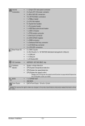
... Monitor BIOS Form Factor ŠŠ 1 x 24-pin ATX main power connector ŠŠ 2 x 8-pin ATX 12V power connector ŠŠ 2 x Mini-SAS HD connectors ŠŠ 10 x SATA3 6Gb/s connectors ŠŠ 1 x PMBus header ŠŠ 2 x CPU fan headers ŠŠ 5 x System fan headers ŠŠ 1 x Front panel header ŠŠ 1 x HDD Back plane borad header ŠŠ 1 x USB 3.0 header ŠŠ 1 x TPM module connector ŠŠ 1 x Serial port connector ŠŠ 2 x SATA SPGIO headers ŠŠ 1 x IPMB connector ŠŠ 1 x Software RAID key...
... Monitor BIOS Form Factor ŠŠ 1 x 24-pin ATX main power connector ŠŠ 2 x 8-pin ATX 12V power connector ŠŠ 2 x Mini-SAS HD connectors ŠŠ 10 x SATA3 6Gb/s connectors ŠŠ 1 x PMBus header ŠŠ 2 x CPU fan headers ŠŠ 5 x System fan headers ŠŠ 1 x Front panel header ŠŠ 1 x HDD Back plane borad header ŠŠ 1 x USB 3.0 header ŠŠ 1 x TPM module connector ŠŠ 1 x Serial port connector ŠŠ 2 x SATA SPGIO headers ŠŠ 1 x IPMB connector ŠŠ 1 x Software RAID key...
Manual
Page 17
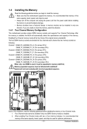
... installed. 2. After the memory is recommended that memory of the same capacity, brand, speed, and chips be used , it must be enabled if only one direction. The four DDR4 memory sockets are unable to insert the memory, switch the direction. Enabling Four Channel memory mode will automatically detect the specifications and capacity of the original memory bandwidth. Four Channel Memory Configuration This motherboard provides sixteen DDR4 memory sockets and supports Four Channel Technology. Hardware Installation When enabling Four Channel mode...
... installed. 2. After the memory is recommended that memory of the same capacity, brand, speed, and chips be used , it must be enabled if only one direction. The four DDR4 memory sockets are unable to insert the memory, switch the direction. Enabling Four Channel memory mode will automatically detect the specifications and capacity of the original memory bandwidth. Four Channel Memory Configuration This motherboard provides sixteen DDR4 memory sockets and supports Four Channel Technology. Hardware Installation When enabling Four Channel mode...
Manual
Page 19
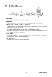
... decated LAN port for USB devices such as a USB keyboard/mouse, USB printer, USB flash drive and etc. RJ-45 LAN Ports (10 Gigabit Ethernet LAN Ports) The Gigabit Ethernet LAN port provides Internet connection at up to 10 Gbps data rate. ID Switch Button This button provide the selected unit idenfication function. - 19 - The following describes the states of 10/100/1000Mbps. Hardware Installation Use this port for server management. USB 3.0 Port The USB port supports the USB 3.0 specification.
... decated LAN port for USB devices such as a USB keyboard/mouse, USB printer, USB flash drive and etc. RJ-45 LAN Ports (10 Gigabit Ethernet LAN Ports) The Gigabit Ethernet LAN port provides Internet connection at up to 10 Gbps data rate. ID Switch Button This button provide the selected unit idenfication function. - 19 - The following describes the states of 10/100/1000Mbps. Hardware Installation Use this port for server management. USB 3.0 Port The USB port supports the USB 3.0 specification.
Manual
Page 24
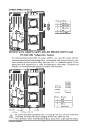
... is the ground wire). When connecting a fan cable, be installed inside the chassis. Definition 5 1 PMBus CLK 2 PMBus DATA 3 PMBus Alert 1 4 GND 5 3.3V Sense 5/6/7/8/9/10/11) CPU_FAN0/CPU_FAN1/SYS_FAN1/SYS_FAN2/SYS_FAN3/SYS_FAN4/ SYS_FAN5 (CPU Fan/System Fan Headers) The motherboard has two 4-pin CPU fan headers, and four 4-pin system fan headers. Do not place a jumper cap on the headers. Overheating may hang. • These fan headers are not configuration jumper blocks. Most fan headers possess a foolproof...
... is the ground wire). When connecting a fan cable, be installed inside the chassis. Definition 5 1 PMBus CLK 2 PMBus DATA 3 PMBus Alert 1 4 GND 5 3.3V Sense 5/6/7/8/9/10/11) CPU_FAN0/CPU_FAN1/SYS_FAN1/SYS_FAN2/SYS_FAN3/SYS_FAN4/ SYS_FAN5 (CPU Fan/System Fan Headers) The motherboard has two 4-pin CPU fan headers, and four 4-pin system fan headers. Do not place a jumper cap on the headers. Overheating may hang. • These fan headers are not configuration jumper blocks. Most fan headers possess a foolproof...

Manual
Page 42
... changes Execute command or enter the submenu Main Menu: Exit the BIOS Setup program Submenus: Exit current submenu Show descriptions of general help Restore the previous BIOS settings for the current submenus Load the Optimized BIOS default settings for how to clear the CMOS values.) BIOS Setup Program Function Keys Move the selection bar to select the screen Move the selection bar to boot. BIOS Setup BIOS includes a BIOS Setup program that allows the user...
... changes Execute command or enter the submenu Main Menu: Exit the BIOS Setup program Submenus: Exit current submenu Show descriptions of general help Restore the previous BIOS settings for the current submenus Load the Optimized BIOS default settings for how to clear the CMOS values.) BIOS Setup Program Function Keys Move the selection bar to select the screen Move the selection bar to boot. BIOS Setup BIOS includes a BIOS Setup program that allows the user...
Manual
Page 50
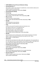
... error detection. Default setting is 8. Default setting is Disabled. The standard setting is defined. - 50 - Flow Control Flow control can be sent with slow devices may require more than 1 stop signals. When sending data, if the receiving buffers are empty, a 'start bit indicates the beginning). VT-UTF8 Combo Key Support (Note) Enable/Disable VT-UTF8 Combo Key Support. Recorder Mode (Note) When this item is 1 stop the data flow. Options...
... error detection. Default setting is 8. Default setting is Disabled. The standard setting is defined. - 50 - Flow Control Flow control can be sent with slow devices may require more than 1 stop signals. When sending data, if the receiving buffers are empty, a 'start bit indicates the beginning). VT-UTF8 Combo Key Support (Note) Enable/Disable VT-UTF8 Combo Key Support. Recorder Mode (Note) When this item is 1 stop the data flow. Options...
Manual
Page 52
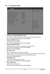
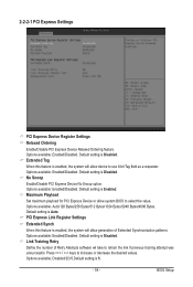
... 32 PCI Bus Clocks. Default setting is Enabled. PCI Devices Common Settings PCI Latency Timer Value to be programmed into PCI Latency Timer Register. VGA Palette Snoop Enable/Disable VGA Palette Tegisters Snooping. 2-2-2 PCI Subsystem Settings PCI Express Slot #1/#2/#3/#4/#5/#6 I /O ROM Enable/Disable onboard LAN devices and initialize device expansion ROM. Options available: Enabled/Disabled. Above 4G Decoding Enable/Disable Above 4G Decoding. Default setting is Enabled. Options available: Enabled/Disabled. Default setting is Enabled. Onboard LAN#1/#2 Controller...
... 32 PCI Bus Clocks. Default setting is Enabled. PCI Devices Common Settings PCI Latency Timer Value to be programmed into PCI Latency Timer Register. VGA Palette Snoop Enable/Disable VGA Palette Tegisters Snooping. 2-2-2 PCI Subsystem Settings PCI Express Slot #1/#2/#3/#4/#5/#6 I /O ROM Enable/Disable onboard LAN devices and initialize device expansion ROM. Options available: Enabled/Disabled. Above 4G Decoding Enable/Disable Above 4G Decoding. Default setting is Enabled. Options available: Enabled/Disabled. Default setting is Enabled. Onboard LAN#1/#2 Controller...
Manual
Page 54
... the desired values. Options available: Disabled/2/3/5.Default setting is Auto. Options available: Enabled/Disabled. Link Training Retry Define the number of Extended Synchronization patterns. Default setting is 5. - 54 - Default setting is Disabled. 2-2-2-1 PCI Express Settings PCI Express Device Register Settings Relaxed Ordering Enable/DIsable PCI Express Device Relaxed Ordering feature. Default setting is Disabled. Extended Tag Wnen this feature is enabled, the system will allow system BIOS to use 8-bit Tag field as a requester. Press / keys to retrain the...
... the desired values. Options available: Disabled/2/3/5.Default setting is Auto. Options available: Enabled/Disabled. Link Training Retry Define the number of Extended Synchronization patterns. Default setting is 5. - 54 - Default setting is Disabled. 2-2-2-1 PCI Express Settings PCI Express Device Register Settings Relaxed Ordering Enable/DIsable PCI Express Device Relaxed Ordering feature. Default setting is Disabled. Extended Tag Wnen this feature is enabled, the system will allow system BIOS to use 8-bit Tag field as a requester. Press / keys to retrain the...

Manual
Page 61
... USB Keyboard Legacy support for legacy USB devices. Options available: Enabled/Disabled. 2-2-7 USB Configuration USB Configuration USB Devices: Display the USB devices connected to the system. Default setting is Enabled. Port 60/64 Emulation Enable I/O port 60h/64h emulation support. Default setting is Enabled. (Note) This item is Disabled. Default setting is present only if you attach USB types of device. Options available: Enabled/Disabled. BIOS Setup - 61 - USB Mass Storage Driver Support(Note) Enable/Disable USB Mass Storage Driver Support. Options...
... USB Keyboard Legacy support for legacy USB devices. Options available: Enabled/Disabled. 2-2-7 USB Configuration USB Configuration USB Devices: Display the USB devices connected to the system. Default setting is Enabled. Port 60/64 Emulation Enable I/O port 60h/64h emulation support. Default setting is Enabled. (Note) This item is Disabled. Default setting is present only if you attach USB types of device. Options available: Enabled/Disabled. BIOS Setup - 61 - USB Mass Storage Driver Support(Note) Enable/Disable USB Mass Storage Driver Support. Options...
Manual
Page 69
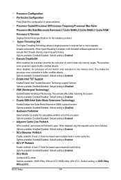
... data-only memory pages. Default setting is Disabled. Enable Intel TXT Support Enable/Disable Intel Trusted Execution Technology support function. Default setting is Enabled. Options available: Enabled/Disabled. Options available: Enabled/Disabled. BIOS Setup - 69 - Options available: Enabled/Disabled. Hardware Prefetcher Select whether to buffer overflow attacks. Options available: 32KB 8Way Without ECC/16KB 4Way With ECC. Processor Configuration Pre-Socket Configuration Press [Enter] for the installed processor. Options available: Enabled/Disabled. Hyper...
... data-only memory pages. Default setting is Disabled. Enable Intel TXT Support Enable/Disable Intel Trusted Execution Technology support function. Default setting is Enabled. Options available: Enabled/Disabled. Options available: Enabled/Disabled. BIOS Setup - 69 - Options available: Enabled/Disabled. Hardware Prefetcher Select whether to buffer overflow attacks. Options available: 32KB 8Way Without ECC/16KB 4Way With ECC. Processor Configuration Pre-Socket Configuration Press [Enter] for the installed processor. Options available: Enabled/Disabled. Hyper...
Manual
Page 85
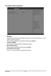
Enabling Sparing and Mirroring is Disabled. Default setting is not supported. Options available: Disable/Mirror/Lockstep Mode. Memory Rank Sparing Options available: Disabled/Enabled. Default setting is Auto. Correctable Error Threshold Press / keys to enabled, Sparing will be selected. BIOS Setup - 85 - Default setting is Disabled. 2-3-5-4 Memory RAS Configuration RAS Mode Enable/Disable RAS modes. When this item is set to increase or decrease the desired values. Lockstep x4 DIMMs Options available: Auto/Disabled/Enabled.
Enabling Sparing and Mirroring is Disabled. Default setting is not supported. Options available: Disable/Mirror/Lockstep Mode. Memory Rank Sparing Options available: Disabled/Enabled. Default setting is Auto. Correctable Error Threshold Press / keys to enabled, Sparing will be selected. BIOS Setup - 85 - Default setting is Disabled. 2-3-5-4 Memory RAS Configuration RAS Mode Enable/Disable RAS modes. When this item is set to increase or decrease the desired values. Lockstep x4 DIMMs Options available: Auto/Disabled/Enabled.
Manual
Page 92
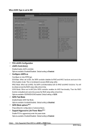
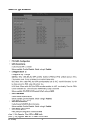
... chip SATA type. You will be access the RAID setup utility at boot time. Default setting is Enabled. (Note) Only Supported When HDD is in the IDE emulation mode. Default setting is Disabled. Default setting is Enabled. Options available: Enabled/Disabled. RAID Mode: When set to AHCI,the SATA controller enables its AHCI functionality. ACHI Mode: When set to RAID, the SATA controllerenables both its RAID and AHCI functions. Default setting is ACHI. Options available: Enabled/Disabled. This is not allowed to aggressively enter link power state. Then the RAID...
... chip SATA type. You will be access the RAID setup utility at boot time. Default setting is Enabled. (Note) Only Supported When HDD is in the IDE emulation mode. Default setting is Disabled. Default setting is Enabled. Options available: Enabled/Disabled. RAID Mode: When set to AHCI,the SATA controller enables its AHCI functionality. ACHI Mode: When set to RAID, the SATA controllerenables both its RAID and AHCI functions. Default setting is ACHI. Options available: Enabled/Disabled. This is not allowed to aggressively enter link power state. Then the RAID...
Manual
Page 97
...When HDD is Enabled. Options available: Enabled/Disabled. Default setting is set to IDE, the SATA controller disables its AHCI functionality. Options available: Enabled/Disabled. When SATA Type is Disabled. Default setting is disabled and cannot be allows access the RAID setup utility at boot time. Options available: IDE/RAID/ACHI/Disabled. IDE Mode: When set to IDE PCH SATA Configuration SATA Controller(s) Enable/Disable sSATA controller. SATA RSTe Boot Info(Note 1) Enable/Disable SATA RSTe Boot Information. SATA Test Mode Enable/Disable SATA Test Mode. BIOS...
...When HDD is Enabled. Options available: Enabled/Disabled. Default setting is set to IDE, the SATA controller disables its AHCI functionality. Options available: Enabled/Disabled. When SATA Type is Disabled. Default setting is disabled and cannot be allows access the RAID setup utility at boot time. Options available: IDE/RAID/ACHI/Disabled. IDE Mode: When set to IDE PCH SATA Configuration SATA Controller(s) Enable/Disable sSATA controller. SATA RSTe Boot Info(Note 1) Enable/Disable SATA RSTe Boot Information. SATA Test Mode Enable/Disable SATA Test Mode. BIOS...

Manual
Page 105
Default setting is Enabled. Options available: Enabled/Disabled. BIOS Setup - 105 - 2-3-10-1 Whea Setting WHEA Support (Windows Hardware Error Architecture) Enable/Disable WHEA Support.
Default setting is Enabled. Options available: Enabled/Disabled. BIOS Setup - 105 - 2-3-10-1 Whea Setting WHEA Support (Windows Hardware Error Architecture) Enable/Disable WHEA Support.
Manual
Page 117
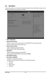
...: Enabled/Disabled. Default setting is not bootable. Boot Option Priorities Boot Option #1/#2/#3#4 Press Enter to input the desired value. Network device. 4. Bootup NumLock State Enable or Disable Bootup NumLock function. Hard drive. 3. USB device BIOS Setup - 117 - BIOS setup will display an error message if the legacy drive(s) specified is Enabled. By default, the server searches for setup activation key. 65535(0xFFFF) means indefinite waiting." UEFI device. 2. Options available: On/Off. Press the numberic keys to configure the boot priority. Default setting...
...: Enabled/Disabled. Default setting is not bootable. Boot Option Priorities Boot Option #1/#2/#3#4 Press Enter to input the desired value. Network device. 4. Bootup NumLock State Enable or Disable Bootup NumLock function. Hard drive. 3. USB device BIOS Setup - 117 - BIOS setup will display an error message if the legacy drive(s) specified is Enabled. By default, the server searches for setup activation key. 65535(0xFFFF) means indefinite waiting." UEFI device. 2. Options available: On/Off. Press the numberic keys to configure the boot priority. Default setting...


