Manual
Page 12
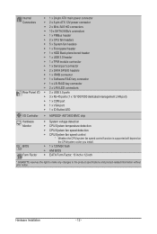
Hardware Installation - 12 - Internal Connectors Rear Panel I/O I/O Controller Hardware Monitor BIOS Form Factor ŠŠ 1 x 24-pin ATX main power connector ŠŠ 2 x 8-pin ATX 12V power connector ŠŠ 2 x Mini-SAS HD connectors ŠŠ 10 x SATA3 6Gb/s connectors ŠŠ 1 x PMBus header ŠŠ 2 x ...cooler you install. ŠŠ 1 x 128 Mbit flash ŠŠ AMI BIOS ŠŠ EATX Form Factor; 13 inch x 12 inch * GIGABYTE reserves the right to make any changes to the product specifications and product-related information without prior notice.
Hardware Installation - 12 - Internal Connectors Rear Panel I/O I/O Controller Hardware Monitor BIOS Form Factor ŠŠ 1 x 24-pin ATX main power connector ŠŠ 2 x 8-pin ATX 12V power connector ŠŠ 2 x Mini-SAS HD connectors ŠŠ 10 x SATA3 6Gb/s connectors ŠŠ 1 x PMBus header ŠŠ 2 x ...cooler you install. ŠŠ 1 x 128 Mbit flash ŠŠ AMI BIOS ŠŠ EATX Form Factor; 13 inch x 12 inch * GIGABYTE reserves the right to make any changes to the product specifications and product-related information without prior notice.
Manual
Page 23
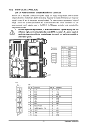
... a power supply is turned off and all the components on the motherboard. Definition 1 GND 51 2 GND 3 GND 4 GND 5 +12V 6 +12V ATX1 84 7 +12V 8 +12V P12V_AUX1 ATX ATX1 13 1 12 24 ATX_12V ATX1 Pin No. 1 2 3 4 5 6 7 8 9 10 11 12 Definition 3.3V 3.3V GND +5V GND +5V GND Power Good 5VSB (stand by +5V...
... a power supply is turned off and all the components on the motherboard. Definition 1 GND 51 2 GND 3 GND 4 GND 5 +12V 6 +12V ATX1 84 7 +12V 8 +12V P12V_AUX1 ATX ATX1 13 1 12 24 ATX_12V ATX1 Pin No. 1 2 3 4 5 6 7 8 9 10 11 12 Definition 3.3V 3.3V GND +5V GND +5V GND Power Good 5VSB (stand by +5V...
