Manual
Page 4
Table of Contents Box Contents...6 Optional Items...6 GA-P67A-UD3R-B3 Motherboard Layout 7 GA-P67A-UD3R-B3 Motherboard Block Diagram 8 Chapter 1 Hardware Installation 9 1-1 Installation Precautions 9 1-2 Product Specifications 10 1-3 Installing the CPU and CPU ... an Expansion Card 18 1-6 Back Panel Connectors 19 1-7 Internal Connectors 21 Chapter 2 BIOS Setup 29 2-1 Startup Screen 30 2-2 The Main Menu 31 2-3 MB Intelligent Tweaker(M.I.T 33 2-4 Standard CMOS Features 41 2-5 Advanced BIOS Features 43 2-6 Integrated Peripherals 45 2-7 Power Management Setup 48 2-8 PC Health Status ...
Table of Contents Box Contents...6 Optional Items...6 GA-P67A-UD3R-B3 Motherboard Layout 7 GA-P67A-UD3R-B3 Motherboard Block Diagram 8 Chapter 1 Hardware Installation 9 1-1 Installation Precautions 9 1-2 Product Specifications 10 1-3 Installing the CPU and CPU ... an Expansion Card 18 1-6 Back Panel Connectors 19 1-7 Internal Connectors 21 Chapter 2 BIOS Setup 29 2-1 Startup Screen 30 2-2 The Main Menu 31 2-3 MB Intelligent Tweaker(M.I.T 33 2-4 Standard CMOS Features 41 2-5 Advanced BIOS Features 43 2-6 Integrated Peripherals 45 2-7 Power Management Setup 48 2-8 PC Health Status ...
Manual
Page 8
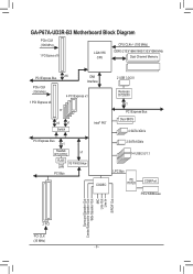
GA-P67A-UD3R-B3 Motherboard Block Diagram PCIe CLK (100 MHz) 1 PCI Express x16 LGA1155 CPU CPU CLK+/- (100 MHz) DDR3 2133/1866/1600/1333/1066 MHz Dual Channel ... MHz) 1 PCI Express x4 x16 DMI Interface 4 PCI Express x1 or x4 x1 Switch Intel® P67 2 USB 3.0/2.0 Renesas D720200 x1 PCI Express Bus Dual BIOS 4 SATA 3Gb/s PCI Express Bus x1 Realtek RTL8111E x1 RJ45 iTE IT8892 Bridge LAN PCI Bus 2 SATA 6Gb/s 14 USB 2.0/1.1 CODEC LPC Bus iTE IT8728...
GA-P67A-UD3R-B3 Motherboard Block Diagram PCIe CLK (100 MHz) 1 PCI Express x16 LGA1155 CPU CPU CLK+/- (100 MHz) DDR3 2133/1866/1600/1333/1066 MHz Dual Channel ... MHz) 1 PCI Express x4 x16 DMI Interface 4 PCI Express x1 or x4 x1 Switch Intel® P67 2 USB 3.0/2.0 Renesas D720200 x1 PCI Express Bus Dual BIOS 4 SATA 3Gb/s PCI Express Bus x1 Realtek RTL8111E x1 RJ45 iTE IT8892 Bridge LAN PCI Bus 2 SATA 6Gb/s 14 USB 2.0/1.1 CODEC LPC Bus iTE IT8728...
Manual
Page 30
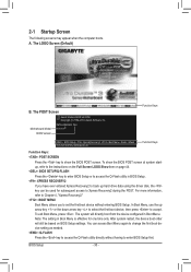
... first boot device setting as needed. : Q-FLASH Press the key to access the Q-Flash utility directly without entering BIOS Setup. The system will still be used for one time only. Motherboard Model BIOS Version P67A-UD3R-B3 F4d . . . . : BIOS Setup : XpressRecovery2 : Boot Menu : Qflash 11/12/2010-P67-7A89UG03C-00 Function Keys Function Keys Function Keys...
... first boot device setting as needed. : Q-FLASH Press the key to access the Q-Flash utility directly without entering BIOS Setup. The system will still be used for one time only. Motherboard Model BIOS Version P67A-UD3R-B3 F4d . . . . : BIOS Setup : XpressRecovery2 : Boot Menu : Qflash 11/12/2010-P67-7A89UG03C-00 Function Keys Function Keys Function Keys...
Manual
Page 62
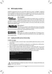
...- 62 - Motherboards that matches your motherboard model. 2. From GIGABYTE's website, download the latest compressed BIOS update file that support DualBIOS have two BIOS onboard, a main BIOS and a backup BIOS. Restart the system. For the sake of your USB flash ...BIOS will take over on the main BIOS. However, if the BIOS update file is Q-Flash™? P67A-UD3R-B3 F4d . . . . : BIOS Setup : XpressRecovery2 : Boot Menu : Qflash 11/12/2010-P67-7A89UG03C-00 Because BIOS flashing is @BIOS™? @BIOS allows you from the nearest @BIOS server 4-2-1 Updating the BIOS...
...- 62 - Motherboards that matches your motherboard model. 2. From GIGABYTE's website, download the latest compressed BIOS update file that support DualBIOS have two BIOS onboard, a main BIOS and a backup BIOS. Restart the system. For the sake of your USB flash ...BIOS will take over on the main BIOS. However, if the BIOS update file is Q-Flash™? P67A-UD3R-B3 F4d . . . . : BIOS Setup : XpressRecovery2 : Boot Menu : Qflash 11/12/2010-P67-7A89UG03C-00 Because BIOS flashing is @BIOS™? @BIOS allows you from the nearest @BIOS server 4-2-1 Updating the BIOS...


