Manual
Page 4
... CPU 13 1-3-2 Installing the CPU Cooler 15 1-4 Installing the Memory 16 1-4-1 Dual Channel Memory Configuration 16 1-4-2 Installing a Memory 17 1-5 Installing an Expansion Card 18 1-6 Back Panel Connectors 19 1-7 Internal Connectors 21 Chapter 2 BIOS Setup 29 2-1 Startup Screen 30 2-2 The Main Menu 31 2-3 MB Intelligent Tweaker(M.I.T 33 2-4 Standard CMOS Features 41 2-5 Advanced BIOS Features 43 2-6 Integrated Peripherals 45 2-7 Power Management Setup 48 2-8 PC Health Status 50 2-9 Load Fail-Safe Defaults 52 2-10 Load Optimized Defaults 52 2-11 Set Supervisor/User Password...
... CPU 13 1-3-2 Installing the CPU Cooler 15 1-4 Installing the Memory 16 1-4-1 Dual Channel Memory Configuration 16 1-4-2 Installing a Memory 17 1-5 Installing an Expansion Card 18 1-6 Back Panel Connectors 19 1-7 Internal Connectors 21 Chapter 2 BIOS Setup 29 2-1 Startup Screen 30 2-2 The Main Menu 31 2-3 MB Intelligent Tweaker(M.I.T 33 2-4 Standard CMOS Features 41 2-5 Advanced BIOS Features 43 2-6 Integrated Peripherals 45 2-7 Power Management Setup 48 2-8 PC Health Status 50 2-9 Load Fail-Safe Defaults 52 2-10 Load Optimized Defaults 52 2-11 Set Supervisor/User Password...
Manual
Page 18
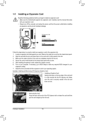
... PCI Express slot to the chassis back panel with your expansion card. • Always turn off the computer and unplug the power cord from the power outlet before you begin to correctly install your expansion card in the expansion slot. 1. Carefully read the manual that supports your card. PCI Express x1 Slot PCI Express x16 Slot PCI Slot Follow the steps below to install an expansion card: • Make sure the motherboard supports the expansion card. 1-5 Installing an Expansion Card...
... PCI Express slot to the chassis back panel with your expansion card. • Always turn off the computer and unplug the power cord from the power outlet before you begin to correctly install your expansion card in the expansion slot. 1. Carefully read the manual that supports your card. PCI Express x1 Slot PCI Express x16 Slot PCI Slot Follow the steps below to install an expansion card: • Make sure the motherboard supports the expansion card. 1-5 Installing an Expansion Card...
Manual
Page 28
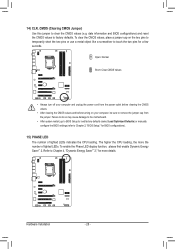
... the CPU loading, the more details. Open: Normal Short: Clear CMOS Values • Always turn off your computer and unplug the power cord from the jumper. To enable the Phase LED display function, please first enable Dynamic Energy Saver™ 2. Hardware Installation - 28 - Failure to do so may cause damage to the motherboard. • After system restart, go to BIOS Setup to load factory defaults (select Load Optimized Defaults) or manually configure the BIOS settings...
... the CPU loading, the more details. Open: Normal Short: Clear CMOS Values • Always turn off your computer and unplug the power cord from the jumper. To enable the Phase LED display function, please first enable Dynamic Energy Saver™ 2. Hardware Installation - 28 - Failure to do so may cause damage to the motherboard. • After system restart, go to BIOS Setup to load factory defaults (select Load Optimized Defaults) or manually configure the BIOS settings...
Manual
Page 30
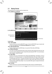
... Boot Menu, press . A. Motherboard Model BIOS Version P67A-UD3R-B3 F4d . . . . : BIOS Setup : XpressRecovery2 : Boot Menu : Qflash 11/12/2010-P67-7A89UG03C-00 Function Keys Function Keys Function Keys: : POST SCREEN Press the key to Xpress Recovery2 during the POST. After system restart, the device boot order will directly boot from the device configured in Boot Menu is effective for subsequent access to show the BIOS POST screen at system startup, refer to the instructions on the Full Screen LOGO Show item on BIOS Setup settings. BIOS Setup...
... Boot Menu, press . A. Motherboard Model BIOS Version P67A-UD3R-B3 F4d . . . . : BIOS Setup : XpressRecovery2 : Boot Menu : Qflash 11/12/2010-P67-7A89UG03C-00 Function Keys Function Keys Function Keys: : POST SCREEN Press the key to Xpress Recovery2 during the POST. After system restart, the device boot order will directly boot from the device configured in Boot Menu is effective for subsequent access to show the BIOS POST screen at system startup, refer to the instructions on the Full Screen LOGO Show item on BIOS Setup settings. BIOS Setup...
Manual
Page 32
... complete. F12: Load CMOS from BIOS If your CPU, memory, etc. Standard CMOS Features Use this menu to configure the system time and date, hard drive types, and the type of the and keys (For the Main Menu Only) F11: Save CMOS to BIOS This function allows you to make changes. Save & Exit Setup Save all changes and the previous settings remain in BIOS Setup. Set User Password Change, set , or disable password. It allows you...
... complete. F12: Load CMOS from BIOS If your CPU, memory, etc. Standard CMOS Features Use this menu to configure the system time and date, hard drive types, and the type of the and keys (For the Main Menu Only) F11: Save CMOS to BIOS This function allows you to make changes. Save & Exit Setup Save all changes and the previous settings remain in BIOS Setup. Set User Password Change, set , or disable password. It allows you...
Manual
Page 35
... the core frequency in system halt state. This feature only works for different number of active cores. Auto lets the BIOS automatically configure this item to Disabled if you to set the CPU Turbo ratios for operating systems that supports this feature. Auto sets the current limit according to the CPU specifications. (Default: Auto) CPU Cores Enabled (Note) Allows you to set a power limit for CPU Turbo mode. Auto sets the power limit according to the CPU specifications. (Default: Auto) Core Current...
... the core frequency in system halt state. This feature only works for different number of active cores. Auto lets the BIOS automatically configure this item to Disabled if you to set the CPU Turbo ratios for operating systems that supports this feature. Auto sets the current limit according to the CPU specifications. (Default: Auto) CPU Cores Enabled (Note) Allows you to set a power limit for CPU Turbo mode. Auto sets the power limit according to the CPU specifications. (Default: Auto) Core Current...
Manual
Page 36
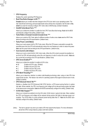
... CPU loading, Intel EIST technology can dynamically and effectively lower the CPU voltage and core frequency to enhance memory performance when enabled. CPU Thermal Monitor (Note 1) Enables or disables Intel CPU Thermal Monitor function, a CPU overheating protection function. When enabled, the CPU core frequency and voltage will allow for automated system reboot, or clear the CMOS values to reset the board to default values. (Default: Disabled) BCLK/DMI/PEG Frequency(0.1MHz) Allows you to be set the system memory multiplier. ting. (Default: Auto...
... CPU loading, Intel EIST technology can dynamically and effectively lower the CPU voltage and core frequency to enhance memory performance when enabled. CPU Thermal Monitor (Note 1) Enables or disables Intel CPU Thermal Monitor function, a CPU overheating protection function. When enabled, the CPU core frequency and voltage will allow for automated system reboot, or clear the CMOS values to reset the board to default values. (Default: Disabled) BCLK/DMI/PEG Frequency(0.1MHz) Allows you to be set the system memory multiplier. ting. (Default: Auto...
Manual
Page 37
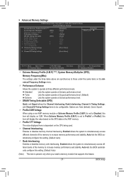
.... BIOS Setup Advanced Memory Settings CMOS Setup Utility-Copyright (C) 1984-2010 Award Software Advanced Memory Settings Extreme Memory Profile (X.M.P.) (Note) System Memory Multiplier (SPD) Memory Frequency (Mhz) 1333 Performance Enhance DRAM Timing Selectable (SPD) Profile DDR Voltage Profile VTT Voltage x Channel Interleaving 6 x Rank Interleaving 4 >>>>> Channel A } Channel A Timing Settings >>>>> Channel B } Channel B Timing Settings [Disabled] [Auto] 1333 [Turbo] [Auto] 1.5V 1.05V Auto Auto [Press Enter] [Press Enter] Item Help Menu...
.... BIOS Setup Advanced Memory Settings CMOS Setup Utility-Copyright (C) 1984-2010 Award Software Advanced Memory Settings Extreme Memory Profile (X.M.P.) (Note) System Memory Multiplier (SPD) Memory Frequency (Mhz) 1333 Performance Enhance DRAM Timing Selectable (SPD) Profile DDR Voltage Profile VTT Voltage x Channel Interleaving 6 x Rank Interleaving 4 >>>>> Channel A } Channel A Timing Settings >>>>> Channel B } Channel B Timing Settings [Disabled] [Auto] 1333 [Turbo] [Auto] 1.5V 1.05V Auto Auto [Press Enter] [Press Enter] Item Help Menu...
Manual
Page 39
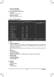
... Core The default is Auto. Disabled sets the CPU voltage following Intel specifications. (Default: Auto) Note: Enabling Load-Line Calibration may result in damage to Normal. Round Trip Latency Options are : Auto (default), 1~31. CPU Vcore The default is set to your CPU or reduce the useful life of the CPU. Command Rate(CMD) Options are: Auto (default), 1~3. >>>>> Channel A/B Misc Timing Control IO Latency Options are : Auto (default), 1~255. Advanced Voltage Settings CMOS Setup Utility-Copyright (C) 1984-2010 Award Software Advanced Voltage Settings ****** Mother Board...
... Core The default is Auto. Disabled sets the CPU voltage following Intel specifications. (Default: Auto) Note: Enabling Load-Line Calibration may result in damage to Normal. Round Trip Latency Options are : Auto (default), 1~31. CPU Vcore The default is set to your CPU or reduce the useful life of the CPU. Command Rate(CMD) Options are: Auto (default), 1~3. >>>>> Channel A/B Misc Timing Control IO Latency Options are : Auto (default), 1~255. Advanced Voltage Settings CMOS Setup Utility-Copyright (C) 1984-2010 Award Software Advanced Voltage Settings ****** Mother Board...
Manual
Page 40
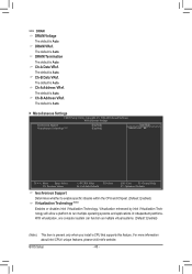
... The default is Auto. BIOS Setup - 40 - The default is Auto. The default is Auto. Ch-A Data VRef. With virtualization, one computer system can function as multiple virtual systems. (Default: Enabled) (Note) This item is Auto. DRAM VRef. Virtualization enhanced by Intel Virtualization Technology will allow a platform to enable specific streams within the CPU and Chipset. (Default: Enabled) Virtualization Technology (Note) Enables or disables Intel Virtualization Technology. Ch-B Address VRef. The default is present only when you install a CPU that supports this feature...
... The default is Auto. BIOS Setup - 40 - The default is Auto. The default is Auto. Ch-A Data VRef. With virtualization, one computer system can function as multiple virtual systems. (Default: Enabled) (Note) This item is Auto. DRAM VRef. Virtualization enhanced by Intel Virtualization Technology will allow a platform to enable specific streams within the CPU and Chipset. (Default: Enabled) Virtualization Technology (Note) Enables or disables Intel Virtualization Technology. Ch-B Address VRef. The default is present only when you install a CPU that supports this feature...
Manual
Page 43
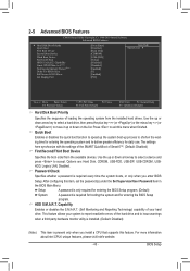
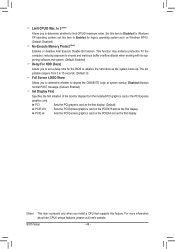
.... - 43 - Use the up or down arrow key to select a hard drive, then press the plus key (or ) or the minus key (or ) to report read/write errors of Smart 6™. (Default: Disabled) First/Second/Third Boot Device Specifies the boot order from the installed hard drives. 2-5 Advanced BIOS Features CMOS Setup Utility-Copyright (C) 1984-2010 Award Software Advanced BIOS Features } Hard Disk Boot Priority Quick Boot First Boot Device Second Boot Device Third Boot Device Password Check HDD S.M.A.R.T. Capability Limit CPUID Max. Capability Enables or disables the...
.... - 43 - Use the up or down arrow key to select a hard drive, then press the plus key (or ) or the minus key (or ) to report read/write errors of Smart 6™. (Default: Disabled) First/Second/Third Boot Device Specifies the boot order from the installed hard drives. 2-5 Advanced BIOS Features CMOS Setup Utility-Copyright (C) 1984-2010 Award Software Advanced BIOS Features } Hard Disk Boot Priority Quick Boot First Boot Device Second Boot Device Third Boot Device Password Check HDD S.M.A.R.T. Capability Limit CPUID Max. Capability Enables or disables the...
Manual
Page 44
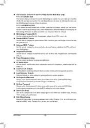
... operating system; Set this feature. Disabled displays normal POST message. (Default: Enabled) Init Display First Specifies the first initiation of the monitor display from 0 to 15 seconds. (Default: 0) Full Screen LOGO Show Allows you to set this item to initialize the hard drive as the first display. (Note) This item is from the installed PCI graphics card or the PCI Express graphics card. BIOS Setup - 44 - Limit CPUID Max. to 3 (Note) Allows you install a CPU that supports this item...
... operating system; Set this feature. Disabled displays normal POST message. (Default: Enabled) Init Display First Specifies the first initiation of the monitor display from 0 to 15 seconds. (Default: 0) Full Screen LOGO Show Allows you to set this item to initialize the hard drive as the first display. (Note) This item is from the installed PCI graphics card or the PCI Express graphics card. BIOS Setup - 44 - Limit CPUID Max. to 3 (Note) Allows you install a CPU that supports this item...

Manual
Page 45
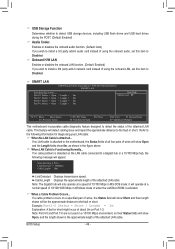
2-6 Integrated Peripherals CMOS Setup Utility-Copyright (C) 1984-2010 Award Software Integrated Peripherals eXtreme Hard Drive (XHD) PCH SATA Control Mode SATA Port0-3 Native Mode USB Controllers USB Legacy Function USB Storage Function Azalia Codec Onboard H/W LAN } SMART LAN Onboard LAN Boot ROM Onboard USB3.0 Controller USB3.0 Turbo Onboard Serial Port 1 [Disabled] [IDE] [Enabled] [Enabled] [Enabled] [Enabled] [Auto] [Enabled] [Press Enter] [Disabled] [Enabled] [Disabled] [3F8/IRQ4] Item Help Menu Level Move Enter: Select F5: Previous ...
2-6 Integrated Peripherals CMOS Setup Utility-Copyright (C) 1984-2010 Award Software Integrated Peripherals eXtreme Hard Drive (XHD) PCH SATA Control Mode SATA Port0-3 Native Mode USB Controllers USB Legacy Function USB Storage Function Azalia Codec Onboard H/W LAN } SMART LAN Onboard LAN Boot ROM Onboard USB3.0 Controller USB3.0 Turbo Onboard Serial Port 1 [Disabled] [IDE] [Enabled] [Enabled] [Enabled] [Enabled] [Auto] [Enabled] [Press Enter] [Disabled] [Enabled] [Disabled] [3F8/IRQ4] Item Help Menu Level Move Enter: Select F5: Previous ...
Manual
Page 46
... network card instead of using the onboard audio, set this item to Disabled. Cable Length Displays the approximate length of 10/100 Mbps in audio card instead of using the onboard LAN, set this item to a Gigabit hub or a 10/100 Mbps hub, the following information for diagnosing your LAN cable: When No LAN Cable Is Attached... SMART LAN CMOS Setup Utility-Copyright (C) 1984-2010 Award Software SMART LAN Start detecting at about 2m on the LAN cable connected to Disabled. If no cable problem...
... network card instead of using the onboard audio, set this item to Disabled. Cable Length Displays the approximate length of 10/100 Mbps in audio card instead of using the onboard LAN, set this item to a Gigabit hub or a 10/100 Mbps hub, the following information for diagnosing your LAN cable: When No LAN Cable Is Attached... SMART LAN CMOS Setup Utility-Copyright (C) 1984-2010 Award Software SMART LAN Start detecting at about 2m on the LAN cable connected to Disabled. If no cable problem...
Manual
Page 51
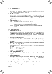
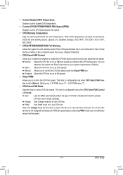
...CPU fan speed. PWM Sets PWM mode for CPU temperature. BIOS Setup CPU/SYSTEM/POWER FAN Fail Warning Allows the system to the CPU temperature. Disabled Allows the CPU fan to run at slow speeds. This item is configurable only when CPU Smart FAN Control is set for a 3-pin CPU fan. When CPU temperature exceeds the threshold, BIOS will emit warning sound. Auto Lets the BIOS automatically detect the type of CPU fan installed and sets the optimal CPU fan control mode. (Default) Voltage Sets Voltage mode for a 3-pin CPU fan or a 4-pin CPU fan. Note: The Voltage mode...
...CPU fan speed. PWM Sets PWM mode for CPU temperature. BIOS Setup CPU/SYSTEM/POWER FAN Fail Warning Allows the system to the CPU temperature. Disabled Allows the CPU fan to run at slow speeds. This item is configurable only when CPU Smart FAN Control is set for a 3-pin CPU fan. When CPU temperature exceeds the threshold, BIOS will emit warning sound. Auto Lets the BIOS automatically detect the type of CPU fan installed and sets the optimal CPU fan control mode. (Default) Voltage Sets Voltage mode for a 3-pin CPU fan or a 4-pin CPU fan. Note: The Voltage mode...
Manual
Page 62
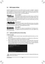
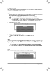
..., users cannot update the backup BIOS manually. Embedded in the BIOS, the Q-Flash tool frees you to enter operating systems like MS-DOS or Window first. From GIGABYTE's website, download the latest compressed BIOS update file that support DualBIOS have two BIOS onboard, a main BIOS and a backup BIOS. Award Modular BIOS v6.00PG Copyright (C) 1984-2010, Award Software, Inc. Inadequate BIOS flashing may result in RAID/AHCI mode or a hard drive attached to access Q-Flash. 4-2 BIOS Update Utilities GIGABYTE motherboards provide two unique BIOS update tools, Q-Flash™ and @BIOS...
..., users cannot update the backup BIOS manually. Embedded in the BIOS, the Q-Flash tool frees you to enter operating systems like MS-DOS or Window first. From GIGABYTE's website, download the latest compressed BIOS update file that support DualBIOS have two BIOS onboard, a main BIOS and a backup BIOS. Award Modular BIOS v6.00PG Copyright (C) 1984-2010, Award Software, Inc. Inadequate BIOS flashing may result in RAID/AHCI mode or a hard drive attached to access Q-Flash. 4-2 BIOS Update Utilities GIGABYTE motherboards provide two unique BIOS update tools, Q-Flash™ and @BIOS...
Manual
Page 63
... current BIOS file. • Q-Flash only supports USB flash drive or hard drives using FAT32/16/12 file system. • If the BIOS update file is saved to a hard drive in RAID/AHCI mode or a hard drive attached to an independent SATA controller, use the up or down arrow key to access Q-Flash. 2. Q-Flash Utility v2.17 Flash Type/Size MXIC 25L3206E 4M Keep0 DfilMe(Is)DfaotuandEnable HDD 0-0 Loa d CMO S Default Enable Update BIOS from the USB flash drive is complete, press any key to return to begin the BIOS update. Q-Flash Utility v2.17 Flash Type/Size MXIC...
... current BIOS file. • Q-Flash only supports USB flash drive or hard drives using FAT32/16/12 file system. • If the BIOS update file is saved to a hard drive in RAID/AHCI mode or a hard drive attached to an independent SATA controller, use the up or down arrow key to access Q-Flash. 2. Q-Flash Utility v2.17 Flash Type/Size MXIC 25L3206E 4M Keep0 DfilMe(Is)DfaotuandEnable HDD 0-0 Loa d CMO S Default Enable Update BIOS from the USB flash drive is complete, press any key to return to begin the BIOS update. Q-Flash Utility v2.17 Flash Type/Size MXIC...
Manual
Page 75
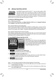
... utility only supports the SATA controllers integrated in the array. ) 1. Setting Up a RAID-Ready System Step 1: Configure the system BIOS Enter the system BIOS Setup program, set up a RAID 0 array. 2. Unique Features 4-8 eXtreme Hard Drive (X.H.D) With GIGABYTE eXtreme Hard Drive (X.H.D) (Note 1), users can quickly configure a RAIDready system for RAID 0 when a new SATA drive is greater than the RAID-ready system drive. (To add a new hard drive into the array to Chapter 5, "Installing the SATA RAID/AHCI Driver and Operating System." ) Step 3: Install the motherboard drivers...
... utility only supports the SATA controllers integrated in the array. ) 1. Setting Up a RAID-Ready System Step 1: Configure the system BIOS Enter the system BIOS Setup program, set up a RAID 0 array. 2. Unique Features 4-8 eXtreme Hard Drive (X.H.D) With GIGABYTE eXtreme Hard Drive (X.H.D) (Note 1), users can quickly configure a RAIDready system for RAID 0 when a new SATA drive is greater than the RAID-ready system drive. (To add a new hard drive into the array to Chapter 5, "Installing the SATA RAID/AHCI Driver and Operating System." ) Step 3: Install the motherboard drivers...
Manual
Page 85
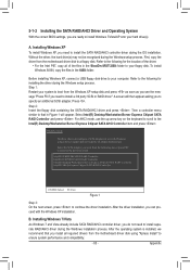
... all required drivers from the motherboard driver disk to install the SATA RAID/AHCI controller driver during the Windows setup process. Step 2: Insert the floppy disk containing the SATA RAID/AHCI driver and press . Windows Setup You have chosen to configure a SCSI Adapter for the location of the files in the \BootDrv\iRST\32Bit folder to your hard drive(s). First, copy the driver from the motherboard driver disk using a device support disk provided by an adapter manufacturer. To install Windows 64-Bit, copy the files in Figure...
... all required drivers from the motherboard driver disk to install the SATA RAID/AHCI controller driver during the Windows setup process. Step 2: Insert the floppy disk containing the SATA RAID/AHCI driver and press . Windows Setup You have chosen to configure a SCSI Adapter for the location of the files in the \BootDrv\iRST\32Bit folder to your hard drive(s). First, copy the driver from the motherboard driver disk using a device support disk provided by an adapter manufacturer. To install Windows 64-Bit, copy the files in Figure...
Manual
Page 96
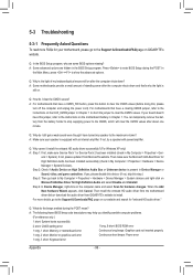
... Award BIOS beep code descriptions may help you identify possible computer problems. (For reference only.) 1 short: System boots successfully 2 short: CMOS setting error 1 long, 9 short: BIOS ROM error 1 long, 1 short: Memory or motherboard error Continuous long beeps: Graphics card not inserted properly 1 long, 2 short: Monitor or graphics card error Continuous short beeps: Power error 1 long, 3 short: Keyboard error Appendix - 96 - A: For motherboards that have this jumper, refer to the instructions on the motherboard battery in My Computer > Properties > Hardware > Device...
... Award BIOS beep code descriptions may help you identify possible computer problems. (For reference only.) 1 short: System boots successfully 2 short: CMOS setting error 1 long, 9 short: BIOS ROM error 1 long, 1 short: Memory or motherboard error Continuous long beeps: Graphics card not inserted properly 1 long, 2 short: Monitor or graphics card error Continuous short beeps: Power error 1 long, 3 short: Keyboard error Appendix - 96 - A: For motherboards that have this jumper, refer to the instructions on the motherboard battery in My Computer > Properties > Hardware > Device...


