Manual
Page 1
GA-P67A-UD3P LGA1155 socket motherboard for Intel® Core™ i7 processors/ Intel® Core™ i5 processors/Intel® Core™ i3 processors/ Intel® Pentium® processors/Intel® Celeron® processors User's Manual Rev. 1001 12ME-P67AU3P-1001R
GA-P67A-UD3P LGA1155 socket motherboard for Intel® Core™ i7 processors/ Intel® Core™ i5 processors/Intel® Core™ i3 processors/ Intel® Pentium® processors/Intel® Celeron® processors User's Manual Rev. 1001 12ME-P67AU3P-1001R
Manual
Page 2
Motherboard GA-P67A-UD3P Nov. 08, 2010 Motherboard GA-P67A-UD3P Nov. 08, 2010
Motherboard GA-P67A-UD3P Nov. 08, 2010 Motherboard GA-P67A-UD3P Nov. 08, 2010

Manual
Page 3
..., drivers, or when looking for technical information. For example, "REV: 1.0" means the revision of the motherboard is the property of this manual may be made by GIGABYTE without GIGABYTE's prior written permission. Example: The trademarks mentioned in the use of the product, read the Quick Installation Guide included with the product. For...
..., drivers, or when looking for technical information. For example, "REV: 1.0" means the revision of the motherboard is the property of this manual may be made by GIGABYTE without GIGABYTE's prior written permission. Example: The trademarks mentioned in the use of the product, read the Quick Installation Guide included with the product. For...
Manual
Page 4
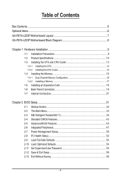
Table of Contents Box Contents...6 Optional Items...6 GA-P67A-UD3P Motherboard Layout 7 GA-P67A-UD3P Motherboard Block Diagram 8 Chapter 1 Hardware Installation 9 1-1 Installation Precautions 9 1-2 Product Specifications 10 1-3 Installing the CPU and CPU Cooler 13 1-3-1 Installing the CPU 13 1-3-2 Installing the CPU Cooler ...
Table of Contents Box Contents...6 Optional Items...6 GA-P67A-UD3P Motherboard Layout 7 GA-P67A-UD3P Motherboard Block Diagram 8 Chapter 1 Hardware Installation 9 1-1 Installation Precautions 9 1-2 Product Specifications 10 1-3 Installing the CPU and CPU Cooler 13 1-3-1 Installing the CPU 13 1-3-2 Installing the CPU Cooler ...
Manual
Page 6
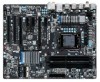
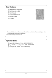
The box contents are for reference only. Optional Items 2-port USB 2.0 bracket (Part No. 12CR1-1UB030-5*R) 2-port SATA power cable (Part No. 12CF1-2SERPW-0*R) COM port cable (Part No. 12CF1-1CM001-3*R) - 6 - Box Contents GA-P67A-UD3P motherboard Motherboard driver disk User's Manual Quick Installation Guide Four SATA cables I/O Shield • The box contents above are subject to change without notice. • The motherboard image is for reference only and the actual items shall depend on the product package you obtain.
The box contents are for reference only. Optional Items 2-port USB 2.0 bracket (Part No. 12CR1-1UB030-5*R) 2-port SATA power cable (Part No. 12CF1-2SERPW-0*R) COM port cable (Part No. 12CF1-1CM001-3*R) - 6 - Box Contents GA-P67A-UD3P motherboard Motherboard driver disk User's Manual Quick Installation Guide Four SATA cables I/O Shield • The box contents above are subject to change without notice. • The motherboard image is for reference only and the actual items shall depend on the product package you obtain.
Manual
Page 7
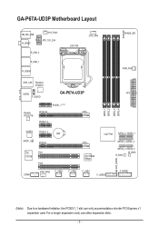
GA-P67A-UD3P Motherboard Layout KB_MS_USB R_SPDIF SYS_FAN1 ATX_12V_2X4 R_USB_2 R_USB_1 R_USB30 LGA1155 CPU_FAN PHASE LED PWR_FAN USB_LAN Renesas D720200 AUDIO GA-P67A-UD3P ATX F_AUDIO DDR3_1 DDR3_2 DDR3_3 DDR3_4 Realtek RTL8111E PCIEX1_1 (Note) PCIEX16 PCIEX1_2 CODEC PCIEX1_3 BAT SPDIF_O PCIEX4 iTE PCI1 IT8728 PCI2 iTE IT8892 Bridge Intel&#...
GA-P67A-UD3P Motherboard Layout KB_MS_USB R_SPDIF SYS_FAN1 ATX_12V_2X4 R_USB_2 R_USB_1 R_USB30 LGA1155 CPU_FAN PHASE LED PWR_FAN USB_LAN Renesas D720200 AUDIO GA-P67A-UD3P ATX F_AUDIO DDR3_1 DDR3_2 DDR3_3 DDR3_4 Realtek RTL8111E PCIEX1_1 (Note) PCIEX16 PCIEX1_2 CODEC PCIEX1_3 BAT SPDIF_O PCIEX4 iTE PCI1 IT8728 PCI2 iTE IT8892 Bridge Intel&#...
Manual
Page 8
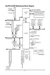
GA-P67A-UD3P Motherboard Block Diagram PCIe CLK (100 MHz) 1 PCI Express x16 LGA1155 CPU CPU CLK+/- (100 MHz) DDR3 2133/1866/1600/1333/1066 MHz Dual Channel Memory ...
GA-P67A-UD3P Motherboard Block Diagram PCIe CLK (100 MHz) 1 PCI Express x16 LGA1155 CPU CPU CLK+/- (100 MHz) DDR3 2133/1866/1600/1333/1066 MHz Dual Channel Memory ...

Manual
Page 9
...Always remove the AC power by your hands dry and first touch a metal object to eliminate static electricity. • Prior to installing the motherboard, please have it on top of an antistatic pad or within the computer casing. • Do not place the computer system on an ... Before using the product, please verify that all cables and power connectors of your hardware components are connected. • To prevent damage to the motherboard, do not have a problem related to wear an electrostatic discharge (ESD) wrist strap when handling electronic com- If you are connected tightly and ...
...Always remove the AC power by your hands dry and first touch a metal object to eliminate static electricity. • Prior to installing the motherboard, please have it on top of an antistatic pad or within the computer casing. • Do not place the computer system on an ... Before using the product, please verify that all cables and power connectors of your hardware components are connected. • To prevent damage to the motherboard, do not have a problem related to wear an electrostatic discharge (ESD) wrist strap when handling electronic com- If you are connected tightly and ...

Manual
Page 12
...;Š Support for Xpress Install ŠŠ Support for Xpress Recovery2 ŠŠ Support for EasyTune * Available functions in EasyTune may differ by motherboard model. ŠŠ Support for Dynamic Energy Saver™ 2 ŠŠ Support for Smart 6™ ŠŠ Support for Auto Green...; Support for Microsoft® Windows® 7/Vista/XP Form Factor ŠŠ ATX Form Factor; 30.5cm x 24.4cm * GIGABYTE reserves the right to make any changes to the product specifications and product-related information without prior notice. Hardware Installation - 12 -
...;Š Support for Xpress Install ŠŠ Support for Xpress Recovery2 ŠŠ Support for EasyTune * Available functions in EasyTune may differ by motherboard model. ŠŠ Support for Dynamic Energy Saver™ 2 ŠŠ Support for Smart 6™ ŠŠ Support for Auto Green...; Support for Microsoft® Windows® 7/Vista/XP Form Factor ŠŠ ATX Form Factor; 30.5cm x 24.4cm * GIGABYTE reserves the right to make any changes to the product specifications and product-related information without prior notice. Hardware Installation - 12 -

Manual
Page 13
...to your hardware specifications including the CPU, graphics card, memory, hard drive, etc. 1-3-1 Installing the CPU A. Locate the alignment keys on the motherboard CPU socket and the notches on the CPU - 13 - Hardware Installation It is not installed, otherwise overheating and dam- age of the CPU...system bus frequency be inserted if oriented incorrectly. (Or you begin to install the CPU: • Make sure that the motherboard supports the CPU. (Go to GIGABYTE's website for the peripherals. LGA1155 CPU Socket Alignment Key Alignment Key Pin One Corner of the CPU. • Do ...
...to your hardware specifications including the CPU, graphics card, memory, hard drive, etc. 1-3-1 Installing the CPU A. Locate the alignment keys on the motherboard CPU socket and the notches on the CPU - 13 - Hardware Installation It is not installed, otherwise overheating and dam- age of the CPU...system bus frequency be inserted if oriented incorrectly. (Or you begin to install the CPU: • Make sure that the motherboard supports the CPU. (Go to GIGABYTE's website for the peripherals. LGA1155 CPU Socket Alignment Key Alignment Key Pin One Corner of the CPU. • Do ...

Manual
Page 14
... front end of the socket cover and use the other to lightly replace the load plate. Step 5: Push the CPU socket lever back into the motherboard CPU socket. B. Follow the steps below to the CPU. To protect the CPU socket, always replace the protective socket cover when the CPU is under...
... front end of the socket cover and use the other to lightly replace the load plate. Step 5: Push the CPU socket lever back into the motherboard CPU socket. B. Follow the steps below to the CPU. To protect the CPU socket, always replace the protective socket cover when the CPU is under...

Manual
Page 15
...are joined closely. (Refer to the CPU fan header (CPU_FAN) on the motherboard. Push down each push pin. 1-3-2 Installing the CPU Cooler Follow the steps below to correctly install the CPU... cooler on the motherboard. (The following procedure uses Intel® boxed cooler as the picture above shows, the installation...3: Place the cooler atop the CPU, aligning the four push pins through the pin holes on the motherboard. If the push pin is inserted as the example cooler.) Direction of the Arrow Sign on the ...
...are joined closely. (Refer to the CPU fan header (CPU_FAN) on the motherboard. Push down each push pin. 1-3-2 Installing the CPU Cooler Follow the steps below to correctly install the CPU... cooler on the motherboard. (The following procedure uses Intel® boxed cooler as the picture above shows, the installation...3: Place the cooler atop the CPU, aligning the four push pins through the pin holes on the motherboard. If the push pin is inserted as the example cooler.) Direction of the Arrow Sign on the ...

Manual
Page 16
.... DS/SS DDR3_2 - The four DDR3 memory sockets are unable to GIGABYTE's website for optimum performance. When enabling Dual Channel mode with two or four memory modules, it is recommended that the motherboard supports the memory. After the memory is installed, the BIOS will double..., brand, speed, and chips be used . (Go to insert the memory, switch the direction. 1-4-1 Dual Channel Memory Configuration This motherboard provides four DDR3 memory sockets and supports Dual Channel Technology. Dual Channel mode cannot be installed in Dual Channel mode. 1. It is installed. ...
.... DS/SS DDR3_2 - The four DDR3 memory sockets are unable to GIGABYTE's website for optimum performance. When enabling Dual Channel mode with two or four memory modules, it is recommended that the motherboard supports the memory. After the memory is installed, the BIOS will double..., brand, speed, and chips be used . (Go to insert the memory, switch the direction. 1-4-1 Dual Channel Memory Configuration This motherboard provides four DDR3 memory sockets and supports Dual Channel Technology. Dual Channel mode cannot be installed in Dual Channel mode. 1. It is installed. ...

Manual
Page 17
... modules in one direction. DDR3 and DDR2 DIMMs are not compatible to each other or DDR DIMMs. Be sure to install DDR3 DIMMs on this motherboard.
... modules in one direction. DDR3 and DDR2 DIMMs are not compatible to each other or DDR DIMMs. Be sure to install DDR3 DIMMs on this motherboard.
Manual
Page 18
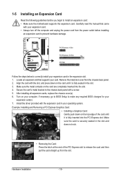
... rock. • Removing the Card: Press the latch at the end of the PCI Express slot to install an expansion card: • Make sure the motherboard supports the expansion card. After installing all expansion cards, replace the chassis cover(s). 6. Example: Installing and Removing a PCI Express Graphics Card: • Installing a Graphics Card...
... rock. • Removing the Card: Press the latch at the end of the PCI Express slot to install an expansion card: • Make sure the motherboard supports the expansion card. After installing all expansion cards, replace the chassis cover(s). 6. Example: Installing and Removing a PCI Express Graphics Card: • Installing a Graphics Card...

Manual
Page 19
..., USB printer, USB flash drive and etc. The following describes the states of the LAN port LEDs. Do not rock it straight out from the motherboard. • When removing the cable, pull it side to side to connect a PS/2 mouse or keyboard. Hardware Installation PS/2 Keyboard/Mouse Port Use this feature...
..., USB printer, USB flash drive and etc. The following describes the states of the LAN port LEDs. Do not rock it straight out from the motherboard. • When removing the cable, pull it side to side to connect a PS/2 mouse or keyboard. Hardware Installation PS/2 Keyboard/Mouse Port Use this feature...

Manual
Page 21
..., make sure your devices are compliant with the connectors you wish to connect. • Before installing the devices, be sure to the connector on the motherboard. - 21 -
..., make sure your devices are compliant with the connectors you wish to connect. • Before installing the devices, be sure to the connector on the motherboard. - 21 -

Manual
Page 22
... the power supply is not connected, the computer will not start. If the 12V power connector is turned off and all the components on the motherboard. 1/2) ATX_12V_2X4/ATX (2x4 12V Power Connector and 2x12 Main Power Connector) With the use of the power connector, the power supply can supply enough stable...
... the power supply is not connected, the computer will not start. If the 12V power connector is turned off and all the components on the motherboard. 1/2) ATX_12V_2X4/ATX (2x4 12V Power Connector and 2x12 Main Power Connector) With the use of the power connector, the power supply can supply enough stable...

Manual
Page 23
... cord. 2. Danger of the battery holder, making them short for one . Most fan headers possess a foolproof insertion design. 3/4/5) CPU_FAN/SYS_FAN1/SYS_FAN2/PWR_FAN (Fan Headers) The motherboard has a 4-pin CPU fan header (CPU_FAN), a 4-pin (SYS_FAN2) and a 3-pin (SYS_ FAN1) system fan headers, and a 3-pin power fan header (PWR_FAN). The...
... cord. 2. Danger of the battery holder, making them short for one . Most fan headers possess a foolproof insertion design. 3/4/5) CPU_FAN/SYS_FAN1/SYS_FAN2/PWR_FAN (Fan Headers) The motherboard has a 4-pin CPU fan header (CPU_FAN), a 4-pin (SYS_FAN2) and a 3-pin (SYS_ FAN1) system fan headers, and a 3-pin power fan header (PWR_FAN). The...

Manual
Page 26
... header supports HD audio by expan- You may require you to use a S/PDIF digital audio cable for digital audio output from your motherboard to your graphics card if you want to mute the back panel audio (only supported when using an HD front panel audio module), ...F_AUDIO (Front Panel Audio Header) The front panel audio header supports Intel High Definition audio (HD) and AC'97 audio. sion cards) for your motherboard to activate AC'97 functionality via the audio software in Chapter 5, "Configuring 2/4/5.1/7.1-Channel Audio." • Audio signals will make the device unable to ...
... header supports HD audio by expan- You may require you to use a S/PDIF digital audio cable for digital audio output from your motherboard to your graphics card if you want to mute the back panel audio (only supported when using an HD front panel audio module), ...F_AUDIO (Front Panel Audio Header) The front panel audio header supports Intel High Definition audio (HD) and AC'97 audio. sion cards) for your motherboard to activate AC'97 functionality via the audio software in Chapter 5, "Configuring 2/4/5.1/7.1-Channel Audio." • Audio signals will make the device unable to ...


