Manual
Page 4
... Box Contents...6 Optional Items...6 GA-P67A-UD3P Motherboard Layout 7 GA-P67A-UD3P Motherboard Block Diagram 8 Chapter 1 Hardware Installation 9 1-1 Installation Precautions 9 1-2 Product Specifications 10 1-3 Installing the CPU and CPU Cooler 13 1-3-1 Installing the CPU 13 1-3-2 Installing the CPU Cooler 15 1-4 Installing the Memory 16 1-4-1 Dual Channel Memory Configuration 16 1-4-2 Installing a Memory 17 1-5 Installing an Expansion Card 18 1-6 Back Panel Connectors 19 1-7 Internal Connectors 21 Chapter 2 BIOS Setup 31 2-1 Startup Screen 32 2-2 The Main Menu 33 2-3 MB...
... Box Contents...6 Optional Items...6 GA-P67A-UD3P Motherboard Layout 7 GA-P67A-UD3P Motherboard Block Diagram 8 Chapter 1 Hardware Installation 9 1-1 Installation Precautions 9 1-2 Product Specifications 10 1-3 Installing the CPU and CPU Cooler 13 1-3-1 Installing the CPU 13 1-3-2 Installing the CPU Cooler 15 1-4 Installing the Memory 16 1-4-1 Dual Channel Memory Configuration 16 1-4-2 Installing a Memory 17 1-5 Installing an Expansion Card 18 1-6 Back Panel Connectors 19 1-7 Internal Connectors 21 Chapter 2 BIOS Setup 31 2-1 Startup Screen 32 2-2 The Main Menu 33 2-3 MB...

Manual
Page 10
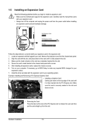
... PCI Express graphics card is to be installed, be sure to install it in the PCIEX16 slot. 1 x PCI Express x16 slot, running at up to x4 mode when ATI CrossFireX™ is built across the SATA 6Gb/s and SATA 3Gb/s channels, the system performance of the RAID set may vary depending on the devices being connected. 1-2 Product Specifications CPU ŠŠ Support for Intel® Core™ i7 processors/Intel® Core™ i5 processors...
... PCI Express graphics card is to be installed, be sure to install it in the PCIEX16 slot. 1 x PCI Express x16 slot, running at up to x4 mode when ATI CrossFireX™ is built across the SATA 6Gb/s and SATA 3Gb/s channels, the system performance of the RAID set may vary depending on the devices being connected. 1-2 Product Specifications CPU ŠŠ Support for Intel® Core™ i7 processors/Intel® Core™ i5 processors...
Manual
Page 11
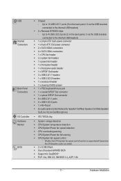
...internal USB headers) ŠŠ 1 x 24-pin ATX main power connector ŠŠ 1 x 8-pin ATX 12V power connector ŠŠ 2 x SATA 6Gb/s connectors ŠŠ 4 x SATA 3Gb/s connectors ŠŠ 1 x CPU fan header ŠŠ 2 x system fan headers ŠŠ 1 x power fan header ŠŠ 1 x front panel header ŠŠ 1 x front panel audio header ŠŠ 1 x S/PDIF Out header ŠŠ 3 x USB 2.0/1.1 headers ŠŠ 1 x USB 3.0/2.0 headers ŠŠ 1 x serial port header ŠŠ 1 x clearing CMOS jumper ŠŠ 1 x PS/2 keyboard/mouse port...
...internal USB headers) ŠŠ 1 x 24-pin ATX main power connector ŠŠ 1 x 8-pin ATX 12V power connector ŠŠ 2 x SATA 6Gb/s connectors ŠŠ 4 x SATA 3Gb/s connectors ŠŠ 1 x CPU fan header ŠŠ 2 x system fan headers ŠŠ 1 x power fan header ŠŠ 1 x front panel header ŠŠ 1 x front panel audio header ŠŠ 1 x S/PDIF Out header ŠŠ 3 x USB 2.0/1.1 headers ŠŠ 1 x USB 3.0/2.0 headers ŠŠ 1 x serial port header ŠŠ 1 x clearing CMOS jumper ŠŠ 1 x PS/2 keyboard/mouse port...
Manual
Page 18
... BIOS changes for your expansion card(s). 7. If necessary, go to BIOS Setup to the chassis back panel with the slot, and press down on the card until it is fully seated in the slot and does not rock. • Removing the Card: Press the latch at the end of the card until it is securely seated in the slot. 3. After installing all expansion cards, replace the chassis cover(s). 6. 1-5 Installing...
... BIOS changes for your expansion card(s). 7. If necessary, go to BIOS Setup to the chassis back panel with the slot, and press down on the card until it is fully seated in the slot and does not rock. • Removing the Card: Press the latch at the end of the card until it is securely seated in the slot. 3. After installing all expansion cards, replace the chassis cover(s). 6. 1-5 Installing...
Manual
Page 28
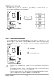
... Short: Clear CMOS Values • Always turn off your computer, be sure to factory defaults. Pin No. Failure to do so may cause damage to the motherboard. • After system restart, go to BIOS Setup to load factory defaults (select Load Optimized Defaults) or manually configure the BIOS settings (refer to clear the CMOS values (e.g. Definition 1 NDCD- 9 1 2 NSIN 10 2 3 NSOUT 4 NDTR- 5 GND 6 NDSR- 7 NRTS- 8 NCTS- 9 NRI- 10 No Pin 15) CLR_CMOS (Clearing CMOS Jumper) Use...
... Short: Clear CMOS Values • Always turn off your computer, be sure to factory defaults. Pin No. Failure to do so may cause damage to the motherboard. • After system restart, go to BIOS Setup to load factory defaults (select Load Optimized Defaults) or manually configure the BIOS settings (refer to clear the CMOS values (e.g. Definition 1 NDCD- 9 1 2 NSIN 10 2 3 NSOUT 4 NDTR- 5 GND 6 NDSR- 7 NRTS- 8 NCTS- 9 NRI- 10 No Pin 15) CLR_CMOS (Clearing CMOS Jumper) Use...

Manual
Page 32
... to access the Q-Flash utility directly without entering BIOS Setup. BIOS Setup - 32 - To exit Boot Menu, press . The LOGO Screen (Default) B. Motherboard Model BIOS Version P67A-UD3P D7 . . . . : BIOS Setup : XpressRecovery2 : Boot Menu : Qflash 10/21/2010-P67-7A89UG0KC-00 Function Keys Function Keys Function Keys: : POST SCREEN Press the key to show the BIOS POST screen at system startup, refer to Xpress Recovery2 during the POST. In Boot Menu, use the up hard drive data using the driver disk, the key can access Boot Menu again to change the first boot device setting...
... to access the Q-Flash utility directly without entering BIOS Setup. BIOS Setup - 32 - To exit Boot Menu, press . The LOGO Screen (Default) B. Motherboard Model BIOS Version P67A-UD3P D7 . . . . : BIOS Setup : XpressRecovery2 : Boot Menu : Qflash 10/21/2010-P67-7A89UG0KC-00 Function Keys Function Keys Function Keys: : POST SCREEN Press the key to show the BIOS POST screen at system startup, refer to Xpress Recovery2 during the POST. In Boot Menu, use the up hard drive data using the driver disk, the key can access Boot Menu again to change the first boot device setting...

Manual
Page 34
... clock, frequency and voltages of your CPU, memory, etc. Standard CMOS Features Use this menu to configure the system time and date, hard drive types, and the type of errors that stop the system boot, etc. Advanced BIOS Features Use this menu to configure the device boot order, advanced features available on the CPU, and the primary display adapter. Integrated Peripherals Use this menu to configure all peripheral devices, such as SATA, USB, integrated audio, and integrated LAN...
... clock, frequency and voltages of your CPU, memory, etc. Standard CMOS Features Use this menu to configure the system time and date, hard drive types, and the type of errors that stop the system boot, etc. Advanced BIOS Features Use this menu to configure the device boot order, advanced features available on the CPU, and the primary display adapter. Integrated Peripherals Use this menu to configure all peripheral devices, such as SATA, USB, integrated audio, and integrated LAN...
Manual
Page 37
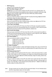
... technology when using an Intel CPU that supports this setting. (Default: Auto) Turbo Ratio (1-Core)/(2-Core)/(3-Core)/(4-Core) (Note) Allows you to determine whether to let the CPU enter C3/C6 mode in order to decrease power consumption. When the CPU current exceeds the specified current limit, the CPU will automatically reduce the core frequency in system halt state. Auto lets the BIOS automatically configure this item to Disabled if you want to manually configure CPU...
... technology when using an Intel CPU that supports this setting. (Default: Auto) Turbo Ratio (1-Core)/(2-Core)/(3-Core)/(4-Core) (Note) Allows you to determine whether to let the CPU enter C3/C6 mode in order to decrease power consumption. When the CPU current exceeds the specified current limit, the CPU will automatically reduce the core frequency in system halt state. Auto lets the BIOS automatically configure this item to Disabled if you want to manually configure CPU...

Manual
Page 38
... operating frequency of CPU base clock and DMI/PCIe bus frequency. BIOS Setup - 38 - Extreme Memory Profile (X.M.P.) (Note 2) Allows the BIOS to read the SPD data on CPU loading, Intel EIST technology can dynamically and effectively lower the CPU voltage and core frequency to memory SPD data. (Default: Auto) Memory Frequency(Mhz) The first memory frequency value is overheated. Auto sets memory multiplier according to decrease average power consumption and heat production. CPU Thermal Monitor (Note 1) Enables or disables Intel CPU Thermal Monitor function, a CPU...
... operating frequency of CPU base clock and DMI/PCIe bus frequency. BIOS Setup - 38 - Extreme Memory Profile (X.M.P.) (Note 2) Allows the BIOS to read the SPD data on CPU loading, Intel EIST technology can dynamically and effectively lower the CPU voltage and core frequency to memory SPD data. (Default: Auto) Memory Frequency(Mhz) The first memory frequency value is overheated. Auto sets memory multiplier according to decrease average power consumption and heat production. CPU Thermal Monitor (Note 1) Enables or disables Intel CPU Thermal Monitor function, a CPU...

Manual
Page 39
..., Channel A Timing Settings, and Channel B Timing Settings items to operate at three different performance levels. Profile DDR Voltage When using a non-XMP memory module or Extreme Memory Profile (X.M.P.) is present only if you install a memory module that supports this item will display the value based on the SPD data on the XMP memory. Options are synchronous to Disabled, this feature. - 39 - Auto lets the BIOS automatically configure this setting. (Default: Auto...
..., Channel A Timing Settings, and Channel B Timing Settings items to operate at three different performance levels. Profile DDR Voltage When using a non-XMP memory module or Extreme Memory Profile (X.M.P.) is present only if you install a memory module that supports this item will display the value based on the SPD data on the XMP memory. Options are synchronous to Disabled, this feature. - 39 - Auto lets the BIOS automatically configure this setting. (Default: Auto...
Manual
Page 41
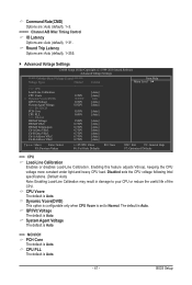
... : Auto (default), 1~255. Advanced Voltage Settings CMOS Setup Utility-Copyright (C) 1984-2010 Award Software Advanced Voltage Settings ****** Mother Board Voltage Control ****** Voltage Types Normal Current >>> CPU Load-Line Calibration [Auto] CPU Vcore 1.250V [Auto] x Dynamic Vcore(DVID) +0.000V Auto QPI/Vtt Voltage 1.050V [Auto] System Agent Voltage 0.920V [Auto] >>> MCH/ICH PCH Core 1.050V [Auto] CPU PLL 1.800V [Auto] >>> DRAM DRAM Voltage 1.500V [Auto] DRAM VRef. 0.750V [Auto] DRAM Termination 0.750V [Auto...
... : Auto (default), 1~255. Advanced Voltage Settings CMOS Setup Utility-Copyright (C) 1984-2010 Award Software Advanced Voltage Settings ****** Mother Board Voltage Control ****** Voltage Types Normal Current >>> CPU Load-Line Calibration [Auto] CPU Vcore 1.250V [Auto] x Dynamic Vcore(DVID) +0.000V Auto QPI/Vtt Voltage 1.050V [Auto] System Agent Voltage 0.920V [Auto] >>> MCH/ICH PCH Core 1.050V [Auto] CPU PLL 1.800V [Auto] >>> DRAM DRAM Voltage 1.500V [Auto] DRAM VRef. 0.750V [Auto] DRAM Termination 0.750V [Auto...
Manual
Page 42
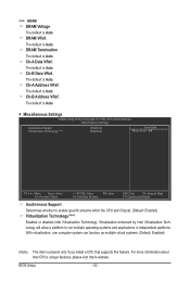
... default is Auto. >>> DRAM DRAM Voltage The default is Auto. Ch-B Data VRef. Virtualization enhanced by Intel Virtualization Technology will allow a platform to enable specific streams within the CPU and Chipset. (Default: Enabled) Virtualization Technology (Note) Enables or disables Intel Virtualization Technology. With virtualization, one computer system can function as multiple virtual systems. (Default: Enabled) (Note) This item is Auto. Miscellaneous Settings CMOS Setup Utility-Copyright (C) 1984-2010 Award Software Miscellaneous Settings Isochronous Support...
... default is Auto. >>> DRAM DRAM Voltage The default is Auto. Ch-B Data VRef. Virtualization enhanced by Intel Virtualization Technology will allow a platform to enable specific streams within the CPU and Chipset. (Default: Enabled) Virtualization Technology (Note) Enables or disables Intel Virtualization Technology. With virtualization, one computer system can function as multiple virtual systems. (Default: Enabled) (Note) This item is Auto. Miscellaneous Settings CMOS Setup Utility-Copyright (C) 1984-2010 Award Software Miscellaneous Settings Isochronous Support...

Manual
Page 45
... disables the S.M.A.R.T. (Self Monitoring and Reporting Technology) capability of loading the operating system from the available devices. Password Check Specifies whether a password is required for booting the system and for daily use. Setup A password is only required for entering the BIOS Setup program. (Default) System A password is required every time the system boots, or only when you install a CPU that supports this feature. 2-5 Advanced BIOS Features CMOS Setup Utility-Copyright (C) 1984-2010 Award Software Advanced BIOS Features } Hard Disk Boot...
... disables the S.M.A.R.T. (Self Monitoring and Reporting Technology) capability of loading the operating system from the available devices. Password Check Specifies whether a password is required for booting the system and for daily use. Setup A password is only required for entering the BIOS Setup program. (Default) System A password is required every time the system boots, or only when you install a CPU that supports this feature. 2-5 Advanced BIOS Features CMOS Setup Utility-Copyright (C) 1984-2010 Award Software Advanced BIOS Features } Hard Disk Boot...

Manual
Page 47
... on using the GIGABYTE X.H.D utility, refer to RAID(XHD) automatically. 2-6 Integrated Peripherals CMOS Setup Utility-Copyright (C) 1984-2010 Award Software Integrated Peripherals eXtreme Hard Drive (XHD) PCH SATA Control Mode SATA Port0-3 Native Mode USB Controllers USB Legacy Function USB Storage Function Azalia Codec Onboard H/W LAN } SMART LAN Onboard LAN Boot ROM R_USB30 Controller R_USB30 Turbo F_USB30 Controller Onboard Serial Port 1 [Disabled] [IDE] [Enabled] [Enabled] [Enabled] [Enabled] [Auto] [Enabled] [Press Enter] [Disabled] [Enabled...
... on using the GIGABYTE X.H.D utility, refer to RAID(XHD) automatically. 2-6 Integrated Peripherals CMOS Setup Utility-Copyright (C) 1984-2010 Award Software Integrated Peripherals eXtreme Hard Drive (XHD) PCH SATA Control Mode SATA Port0-3 Native Mode USB Controllers USB Legacy Function USB Storage Function Azalia Codec Onboard H/W LAN } SMART LAN Onboard LAN Boot ROM R_USB30 Controller R_USB30 Turbo F_USB30 Controller Onboard Serial Port 1 [Disabled] [IDE] [Enabled] [Enabled] [Enabled] [Enabled] [Auto] [Enabled] [Press Enter] [Disabled] [Enabled...

Manual
Page 48
... in Windows mode or when the LAN Boot ROM is detected on a specified pair of wires, the Status field will show Short and then length shown will detect cabling issue and report the approximate distance to Disabled. USB Storage Function Determines whether to detect USB storage devices, including USB flash drives and USB hard drives during the POST. (Default: Enabled) Azalia Codec Enables or disables the onboard audio function. (Default: Auto) If you wish to install a 3rd party add-in network card...
... in Windows mode or when the LAN Boot ROM is detected on a specified pair of wires, the Status field will show Short and then length shown will detect cabling issue and report the approximate distance to Disabled. USB Storage Function Determines whether to detect USB storage devices, including USB flash drives and USB hard drives during the POST. (Default: Enabled) Azalia Codec Enables or disables the onboard audio function. (Default: Auto) If you wish to install a 3rd party add-in network card...

Manual
Page 53
... slow speeds. Disabled Allows the CPU fan to emit warning sound if the CPU/system/power fan is not designed following Intel PWM fan specifications, selecting PWM mode may not effectively reduce the fan speed. - 53 - CPU Smart FAN Mode Specifies how to enable the CPU fan speed control function and adjust the fan speed. BIOS Setup Current System/CPU Temperature Displays current System/CPU temperature. CPU Warning Temperature Sets the warning threshold for a 4-pin CPU fan. You can be set to the CPU temperature. Note: The Voltage mode can adjust the fan speed...
... slow speeds. Disabled Allows the CPU fan to emit warning sound if the CPU/system/power fan is not designed following Intel PWM fan specifications, selecting PWM mode may not effectively reduce the fan speed. - 53 - CPU Smart FAN Mode Specifies how to enable the CPU fan speed control function and adjust the fan speed. BIOS Setup Current System/CPU Temperature Displays current System/CPU temperature. CPU Warning Temperature Sets the warning threshold for a 4-pin CPU fan. You can be set to the CPU temperature. Note: The Voltage mode can adjust the fan speed...

Manual
Page 65
... BIOS update file and press . Make sure the BIOS update file matches your motherboard model. Q-Flash Utility v2.17 Flash Type/Size MXIC 25L3206E 4M Keep DMI Data Enable !L! Update BIOS from Drive and press . • The Save Main BIOS to Drive option allows you to save the BIOS file to access Q-Flash. 2. When the message "Are you save the current BIOS file. • Q-Flash only supports USB flash drive or hard drives using FAT32/16/12 file system. • If the BIOS update file is displayed on the screen. Select HDD...
... BIOS update file and press . Make sure the BIOS update file matches your motherboard model. Q-Flash Utility v2.17 Flash Type/Size MXIC 25L3206E 4M Keep DMI Data Enable !L! Update BIOS from Drive and press . • The Save Main BIOS to Drive option allows you to save the BIOS file to access Q-Flash. 2. When the message "Are you save the current BIOS file. • Q-Flash only supports USB flash drive or hard drives using FAT32/16/12 file system. • If the BIOS update file is displayed on the screen. Select HDD...
Manual
Page 77
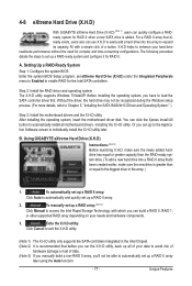
... Features Setting Up a RAID-Ready System Step 1: Configure the system BIOS Enter the system BIOS Setup program, set up a RAID 0 array later using the Auto function. - 77 - Step 2: Install the RAID driver and operating system The X.H.D utility supports Windows 7/Vista/XP. Without the driver, the hard drive may not be able to automatically set up a RAID-ready system and configure it for RAID 0. 4-8 eXtreme Hard Drive (X.H.D) With GIGABYTE eXtreme Hard Drive (X.H.D) (Note 1), users can quickly configure a RAIDready system for RAID 0 when a new SATA drive...
... Features Setting Up a RAID-Ready System Step 1: Configure the system BIOS Enter the system BIOS Setup program, set up a RAID 0 array later using the Auto function. - 77 - Step 2: Install the RAID driver and operating system The X.H.D utility supports Windows 7/Vista/XP. Without the driver, the hard drive may not be able to automatically set up a RAID-ready system and configure it for RAID 0. 4-8 eXtreme Hard Drive (X.H.D) With GIGABYTE eXtreme Hard Drive (X.H.D) (Note 1), users can quickly configure a RAIDready system for RAID 0 when a new SATA drive...
Manual
Page 87
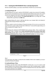
... the motherboard driver disk using a device support disk provided by an adapter manufacturer. Before installing Windows XP, connect a USB floppy disk drive to your hard drive(s). Installing Windows 7/Vista As Windows 7 and Vista already include SATA RAID/AHCI controller driver so you are ready to install Windows 7/Vista/XP onto your computer. A screen will appear. Press . For AHCI mode, use with the Windows XP installation. Refer to the following for use the up arrow key on the keyboard to scroll to the Intel(R) Desktop/Workstation/Server Express Chipset SATA AHCI Controller...
... the motherboard driver disk using a device support disk provided by an adapter manufacturer. Before installing Windows XP, connect a USB floppy disk drive to your hard drive(s). Installing Windows 7/Vista As Windows 7 and Vista already include SATA RAID/AHCI controller driver so you are ready to install Windows 7/Vista/XP onto your computer. A screen will appear. Press . For AHCI mode, use with the Windows XP installation. Refer to the following for use the up arrow key on the keyboard to scroll to the Intel(R) Desktop/Workstation/Server Express Chipset SATA AHCI Controller...
Manual
Page 98
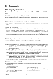
... power to the instructions on the motherboard battery in the BIOS Setup program. Q: Why do I install the onboard HD audio driver successfully? (For Windows XP only) A: Step 1: First, make sure the Microsoft UAA Bus Driver for High Definition Audio and select Disable and Uninstall. A: The following Award BIOS beep code descriptions may help you identify possible computer problems. (For reference only.) 1 short: System boots successfully 2 short: CMOS setting error 1 long, 9 short: BIOS ROM error 1 long, 1 short: Memory or motherboard error Continuous long beeps: Graphics card...
... power to the instructions on the motherboard battery in the BIOS Setup program. Q: Why do I install the onboard HD audio driver successfully? (For Windows XP only) A: Step 1: First, make sure the Microsoft UAA Bus Driver for High Definition Audio and select Disable and Uninstall. A: The following Award BIOS beep code descriptions may help you identify possible computer problems. (For reference only.) 1 short: System boots successfully 2 short: CMOS setting error 1 long, 9 short: BIOS ROM error 1 long, 1 short: Memory or motherboard error Continuous long beeps: Graphics card...


