Manual
Page 1
GA-P67A-UD3P LGA1155 socket motherboard for Intel® Core™ i7 processors/ Intel® Core™ i5 processors/Intel® Core™ i3 processors/ Intel® Pentium® processors/Intel® Celeron® processors User's Manual Rev. 1001 12ME-P67AU3P-1001R
GA-P67A-UD3P LGA1155 socket motherboard for Intel® Core™ i7 processors/ Intel® Core™ i5 processors/Intel® Core™ i3 processors/ Intel® Pentium® processors/Intel® Celeron® processors User's Manual Rev. 1001 12ME-P67AU3P-1001R
Manual
Page 2
Motherboard GA-P67A-UD3P Nov. 08, 2010 Motherboard GA-P67A-UD3P Nov. 08, 2010
Motherboard GA-P67A-UD3P Nov. 08, 2010 Motherboard GA-P67A-UD3P Nov. 08, 2010

Manual
Page 3
...-related information, check on our website at: http://www.gigabyte.com Identifying Your Motherboard Revision The revision number on your motherboard revision before updating motherboard BIOS, drivers, or when looking for technical information. No part of GIGABYTE. For example, "REV: 1.0" means the revision of the motherboard is the property of this manual may be made by...
...-related information, check on our website at: http://www.gigabyte.com Identifying Your Motherboard Revision The revision number on your motherboard revision before updating motherboard BIOS, drivers, or when looking for technical information. No part of GIGABYTE. For example, "REV: 1.0" means the revision of the motherboard is the property of this manual may be made by...
Manual
Page 4
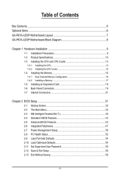
Table of Contents Box Contents...6 Optional Items...6 GA-P67A-UD3P Motherboard Layout 7 GA-P67A-UD3P Motherboard Block Diagram 8 Chapter 1 Hardware Installation 9 1-1 Installation Precautions 9 1-2 Product Specifications 10 1-3 Installing the CPU and CPU Cooler 13 1-3-1 Installing the CPU 13 1-3-2 Installing the CPU Cooler ...
Table of Contents Box Contents...6 Optional Items...6 GA-P67A-UD3P Motherboard Layout 7 GA-P67A-UD3P Motherboard Block Diagram 8 Chapter 1 Hardware Installation 9 1-1 Installation Precautions 9 1-2 Product Specifications 10 1-3 Installing the CPU and CPU Cooler 13 1-3-1 Installing the CPU 13 1-3-2 Installing the CPU Cooler ...
Manual
Page 6
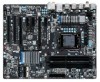
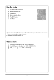
Box Contents GA-P67A-UD3P motherboard Motherboard driver disk User's Manual Quick Installation Guide Four SATA cables I/O Shield • The box contents above are subject to change without notice. • The motherboard image is for reference only and the actual items shall depend on the product package you obtain. The box contents are for reference only. Optional Items 2-port USB 2.0 bracket (Part No. 12CR1-1UB030-5*R) 2-port SATA power cable (Part No. 12CF1-2SERPW-0*R) COM port cable (Part No. 12CF1-1CM001-3*R) - 6 -
Box Contents GA-P67A-UD3P motherboard Motherboard driver disk User's Manual Quick Installation Guide Four SATA cables I/O Shield • The box contents above are subject to change without notice. • The motherboard image is for reference only and the actual items shall depend on the product package you obtain. The box contents are for reference only. Optional Items 2-port USB 2.0 bracket (Part No. 12CR1-1UB030-5*R) 2-port SATA power cable (Part No. 12CF1-2SERPW-0*R) COM port cable (Part No. 12CF1-1CM001-3*R) - 6 -
Manual
Page 7
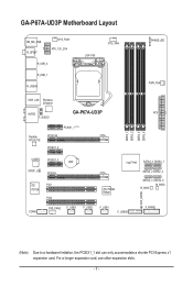
For a longer expansion card, use other expansion slots. - 7 - GA-P67A-UD3P Motherboard Layout KB_MS_USB R_SPDIF SYS_FAN1 ATX_12V_2X4 R_USB_2 R_USB_1 R_USB30 LGA1155 CPU_FAN PHASE LED PWR_FAN USB_LAN Renesas D720200 AUDIO GA-P67A-UD3P ATX F_AUDIO DDR3_1 DDR3_2 DDR3_3 DDR3_4 Realtek RTL8111E PCIEX1_1 (Note) PCIEX16 PCIEX1_2 CODEC PCIEX1_3 BAT SPDIF_O PCIEX4 iTE PCI1 IT8728 PCI2 iTE IT8892 Bridge Intel&#...
For a longer expansion card, use other expansion slots. - 7 - GA-P67A-UD3P Motherboard Layout KB_MS_USB R_SPDIF SYS_FAN1 ATX_12V_2X4 R_USB_2 R_USB_1 R_USB30 LGA1155 CPU_FAN PHASE LED PWR_FAN USB_LAN Renesas D720200 AUDIO GA-P67A-UD3P ATX F_AUDIO DDR3_1 DDR3_2 DDR3_3 DDR3_4 Realtek RTL8111E PCIEX1_1 (Note) PCIEX16 PCIEX1_2 CODEC PCIEX1_3 BAT SPDIF_O PCIEX4 iTE PCI1 IT8728 PCI2 iTE IT8892 Bridge Intel&#...
Manual
Page 8
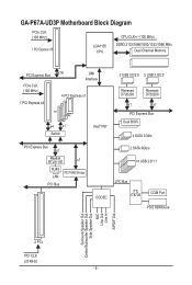
GA-P67A-UD3P Motherboard Block Diagram PCIe CLK (100 MHz) 1 PCI Express x16 LGA1155 CPU CPU CLK+/- (100 MHz) DDR3 2133/1866/1600/1333/1066 MHz Dual Channel Memory ...
GA-P67A-UD3P Motherboard Block Diagram PCIe CLK (100 MHz) 1 PCI Express x16 LGA1155 CPU CPU CLK+/- (100 MHz) DDR3 2133/1866/1600/1333/1066 MHz Dual Channel Memory ...

Manual
Page 9
...high-temperature environment. • Turning on the power, make sure they are connected tightly and securely. • When handling the motherboard, avoid touching any installation steps or have a problem related to the local voltage standard. • Before using the product, ...connectors of your dealer. ponents such as a result of electrostatic discharge (ESD). Chapter 1 Hardware Installation 1-1 Installation Precautions The motherboard contains numerous delicate electronic circuits and components which can lead to damage to system components as well as physical harm to the user...
...high-temperature environment. • Turning on the power, make sure they are connected tightly and securely. • When handling the motherboard, avoid touching any installation steps or have a problem related to the local voltage standard. • Before using the product, ...connectors of your dealer. ponents such as a result of electrostatic discharge (ESD). Chapter 1 Hardware Installation 1-1 Installation Precautions The motherboard contains numerous delicate electronic circuits and components which can lead to damage to system components as well as physical harm to the user...

Manual
Page 12
... ŠŠ Support for Xpress Install ŠŠ Support for Xpress Recovery2 ŠŠ Support for EasyTune * Available functions in EasyTune may differ by motherboard model. ŠŠ Support for Dynamic Energy Saver™ 2 ŠŠ Support for Smart 6™ ŠŠ Support for Auto Green Š...System ŠŠ Support for Microsoft® Windows® 7/Vista/XP Form Factor ŠŠ ATX Form Factor; 30.5cm x 24.4cm * GIGABYTE reserves the right to make any changes to the product specifications and product-related information without prior notice.
... ŠŠ Support for Xpress Install ŠŠ Support for Xpress Recovery2 ŠŠ Support for EasyTune * Available functions in EasyTune may differ by motherboard model. ŠŠ Support for Dynamic Energy Saver™ 2 ŠŠ Support for Smart 6™ ŠŠ Support for Auto Green Š...System ŠŠ Support for Microsoft® Windows® 7/Vista/XP Form Factor ŠŠ ATX Form Factor; 30.5cm x 24.4cm * GIGABYTE reserves the right to make any changes to the product specifications and product-related information without prior notice.

Manual
Page 13
...CPU Socket LGA1155 CPU Notch Notch Triangle Pin One Marking on the computer if the CPU cooler is not recommended that the motherboard supports the CPU. (Go to GIGABYTE's website for the peripherals. The CPU cannot be set the frequency beyond hardware specifications since it does not meet the ...Alignment Key Alignment Key Pin One Corner of the CPU. It is not installed, otherwise overheating and dam- Locate the alignment keys on the motherboard CPU socket and the notches on the CPU. If you may occur. • Set the CPU host frequency in accordance with the CPU ...
...CPU Socket LGA1155 CPU Notch Notch Triangle Pin One Marking on the computer if the CPU cooler is not recommended that the motherboard supports the CPU. (Go to GIGABYTE's website for the peripherals. The CPU cannot be set the frequency beyond hardware specifications since it does not meet the ...Alignment Key Alignment Key Pin One Corner of the CPU. It is not installed, otherwise overheating and dam- Locate the alignment keys on the motherboard CPU socket and the notches on the CPU. If you may occur. • Set the CPU host frequency in accordance with the CPU ...

Manual
Page 14
....) Step 3: Hold the CPU with the socket alignment keys) and gently insert the CPU into position. Step 5: Push the CPU socket lever back into the motherboard CPU socket. Step 2: Remove the CPU socket cover as well. NOTE: Hold the CPU socket lever by the handle, not the lever base portion. Before...
....) Step 3: Hold the CPU with the socket alignment keys) and gently insert the CPU into position. Step 5: Push the CPU socket lever back into the motherboard CPU socket. Step 2: Remove the CPU socket cover as well. NOTE: Hold the CPU socket lever by the handle, not the lever base portion. Before...

Manual
Page 15
... CPU cooler may adhere to the CPU. 1-3-2 Installing the CPU Cooler Follow the steps below to correctly install the CPU cooler on the motherboard. (The following procedure uses Intel® boxed cooler as the picture above shows, the installation is complete. Step 2: Before installing the cooler..., note the direction of the arrow sign on the male push pin. (Turning the push pin along the direction of the motherboard. Hardware Installation Step 6: Finally, attach the power connector of the CPU cooler to install.) Step 3: Place the cooler atop the CPU, aligning...
... CPU cooler may adhere to the CPU. 1-3-2 Installing the CPU Cooler Follow the steps below to correctly install the CPU cooler on the motherboard. (The following procedure uses Intel® boxed cooler as the picture above shows, the installation is complete. Step 2: Before installing the cooler..., note the direction of the arrow sign on the male push pin. (Turning the push pin along the direction of the motherboard. Hardware Installation Step 6: Finally, attach the power connector of the CPU cooler to install.) Step 3: Place the cooler atop the CPU, aligning...

Manual
Page 16
... installed, the BIOS will double the original memory bandwidth. The four DDR3 memory sockets are unable to install the memory: • Make sure that the motherboard supports the memory. It is installed. 2. Enabling Dual Channel memory mode will automatically detect the specifications and capacity of the same capacity, brand, speed, and..., "- -"=No Memory) DDR3_1 DDR3_2 DDR3_3 DDR3_4 Due to prevent hardware damage. • Memory modules have a foolproof design. Dual Channel mode cannot be used . (Go to GIGABYTE's website for optimum performance. Hardware Installation - 16 -
... installed, the BIOS will double the original memory bandwidth. The four DDR3 memory sockets are unable to install the memory: • Make sure that the motherboard supports the memory. It is installed. 2. Enabling Dual Channel memory mode will automatically detect the specifications and capacity of the same capacity, brand, speed, and..., "- -"=No Memory) DDR3_1 DDR3_2 DDR3_3 DDR3_4 Due to prevent hardware damage. • Memory modules have a foolproof design. Dual Channel mode cannot be used . (Go to GIGABYTE's website for optimum performance. Hardware Installation - 16 -

Manual
Page 17
... clips at both ends of the memory, push down on the left, place your memory modules in one direction. Place the memory module on this motherboard. 1-4-2 Installing a Memory Before installing a memory module, make sure to turn off the computer and unplug the power cord from the power outlet to prevent damage...
... clips at both ends of the memory, push down on the left, place your memory modules in one direction. Place the memory module on this motherboard. 1-4-2 Installing a Memory Before installing a memory module, make sure to turn off the computer and unplug the power cord from the power outlet to prevent damage...
Manual
Page 18
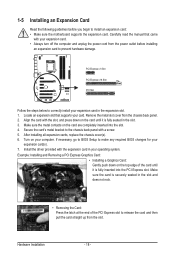
... hardware damage. PCI Express x1 Slot PCI Express x16 Slot PCI Slot Follow the steps below to install an expansion card: • Make sure the motherboard supports the expansion card. Turn on the card are completely inserted into the PCI Express slot. After installing all expansion cards, replace the chassis cover...
... hardware damage. PCI Express x1 Slot PCI Express x16 Slot PCI Slot Follow the steps below to install an expansion card: • Make sure the motherboard supports the expansion card. Turn on the card are completely inserted into the PCI Express slot. After installing all expansion cards, replace the chassis cover...

Manual
Page 19
... etc. Before using this feature, ensure that your audio system provides an optical digital audio in connector. Do not rock it straight out from the motherboard. • When removing the cable, pull it side to side to an external audio system that supports digital coaxial audio. USB 3.0/2.0 Port The USB 3.0 port...
... etc. Before using this feature, ensure that your audio system provides an optical digital audio in connector. Do not rock it straight out from the motherboard. • When removing the cable, pull it side to side to an external audio system that supports digital coaxial audio. USB 3.0/2.0 Port The USB 3.0 port...

Manual
Page 21
... 10) F_AUDIO 11) SPDIF_O 12) F_USB1/F_USB2/F_USB3 13) F_USB30 14) COMA 15) CLR_CMOS 16) PHASE LED Read the following guidelines before turning on the motherboard. - 21 -
... 10) F_AUDIO 11) SPDIF_O 12) F_USB1/F_USB2/F_USB3 13) F_USB30 14) COMA 15) CLR_CMOS 16) PHASE LED Read the following guidelines before turning on the motherboard. - 21 -

Manual
Page 22
... can supply enough stable power to all devices are properly installed. To meet expansion requirements, it is turned off and all the components on the motherboard. Connect the power supply cable to the CPU. Definition 1 GND (Only for 2x4-pin 12V) 2 GND (Only for 2x4-pin 12V) 3 GND 4 GND 5 +12V (Only...
... can supply enough stable power to all devices are properly installed. To meet expansion requirements, it is turned off and all the components on the motherboard. Connect the power supply cable to the CPU. Definition 1 GND (Only for 2x4-pin 12V) 2 GND (Only for 2x4-pin 12V) 3 GND 4 GND 5 +12V (Only...

Manual
Page 23
... BIOS configurations, date, and time information) in accordance with fan speed control design. Gently remove the battery from overheating. The motherboard supports CPU fan speed control, which requires the use a metal object like a screwdriver to prevent your CPU and system from ...dealer if you are not configuration jumper blocks. Turn off your computer and unplug the power cord. 2. 3/4/5) CPU_FAN/SYS_FAN1/SYS_FAN2/PWR_FAN (Fan Headers) The motherboard has a 4-pin CPU fan header (CPU_FAN), a 4-pin (SYS_FAN2) and a 3-pin (SYS_ FAN1) system fan headers, and a 3-pin power fan...
... BIOS configurations, date, and time information) in accordance with fan speed control design. Gently remove the battery from overheating. The motherboard supports CPU fan speed control, which requires the use a metal object like a screwdriver to prevent your CPU and system from ...dealer if you are not configuration jumper blocks. Turn off your computer and unplug the power cord. 2. 3/4/5) CPU_FAN/SYS_FAN1/SYS_FAN2/PWR_FAN (Fan Headers) The motherboard has a 4-pin CPU fan header (CPU_FAN), a 4-pin (SYS_FAN2) and a 3-pin (SYS_ FAN1) system fan headers, and a 3-pin power fan...

Manual
Page 26
...SPDIFO 1 2 GND Hardware Installation - 26 - You may require you to use a S/PDIF digital audio cable for digital audio output from your motherboard to this header. If your chassis front panel audio module to your expansion card. For example, some graphics cards may connect your chassis provides ...'97 Front Panel Audio: Pin No. For information about connecting the front panel audio module that has separated connectors on both of the motherboard header. 10) F_AUDIO (Front Panel Audio Header) The front panel audio header supports Intel High Definition audio (HD) and AC'97...
...SPDIFO 1 2 GND Hardware Installation - 26 - You may require you to use a S/PDIF digital audio cable for digital audio output from your motherboard to this header. If your chassis front panel audio module to your expansion card. For example, some graphics cards may connect your chassis provides ...'97 Front Panel Audio: Pin No. For information about connecting the front panel audio module that has separated connectors on both of the motherboard header. 10) F_AUDIO (Front Panel Audio Header) The front panel audio header supports Intel High Definition audio (HD) and AC'97...


