Manual
Page 1
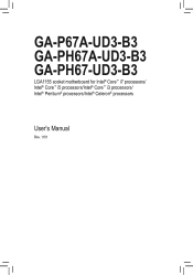
GA-P67A-UD3-B3 GA-PH67A-UD3-B3 GA-PH67-UD3-B3 LGA1155 socket motherboard for Intel® Core™ i7 processors/ Intel® Core™ i5 processors/Intel® Core™ i3 processors/ Intel® Pentium® processors/Intel® Celeron® processors User's Manual Rev. 1101
GA-P67A-UD3-B3 GA-PH67A-UD3-B3 GA-PH67-UD3-B3 LGA1155 socket motherboard for Intel® Core™ i7 processors/ Intel® Core™ i5 processors/Intel® Core™ i3 processors/ Intel® Pentium® processors/Intel® Celeron® processors User's Manual Rev. 1101
Manual
Page 2
Motherboard GA-P67A-UD3-B3/GA-PH67A-UD3-B3/GA-PH67-UD3-B3 Jan. 14, 2011 Motherboard GA-P67A-UD3-B3/ GA-PH67A-UD3-B3/ GA-PH67-UD3-B3 Jan. 14, 2011
Motherboard GA-P67A-UD3-B3/GA-PH67A-UD3-B3/GA-PH67-UD3-B3 Jan. 14, 2011 Motherboard GA-P67A-UD3-B3/ GA-PH67A-UD3-B3/ GA-PH67-UD3-B3 Jan. 14, 2011
Manual
Page 3
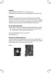
...of documentations: For quick set-up of GIGABYTE. For product-related information, check on our website at: http://www.gigabyte.com Identifying Your Motherboard Revision The revision number on your motherboard revision before updating motherboard BIOS, drivers, or when looking for technical information. ...this manual is protected by any form or by copyright laws and is 1.0. Check your motherboard looks like this manual may be made by GIGABYTE without GIGABYTE's prior written permission. Documentation Classifications In order to their respective owners. All rights reserved....
...of documentations: For quick set-up of GIGABYTE. For product-related information, check on our website at: http://www.gigabyte.com Identifying Your Motherboard Revision The revision number on your motherboard revision before updating motherboard BIOS, drivers, or when looking for technical information. ...this manual is protected by any form or by copyright laws and is 1.0. Check your motherboard looks like this manual may be made by GIGABYTE without GIGABYTE's prior written permission. Documentation Classifications In order to their respective owners. All rights reserved....
Manual
Page 4
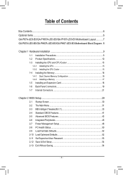
Table of Contents Box Contents...6 Optional Items...6 GA-P67A-UD3-B3/GA-PH67A-UD3-B3/GA-PH67-UD3-B3 Motherboard Layout............7 GA-P67A-UD3-B3/GA-PH67A-UD3-B3/GA-PH67-UD3-B3 Motherboard Block Diagram.. 8 Chapter 1 Hardware Installation 9 1-1 Installation Precautions 9 1-2 Product Specifications 10 1-3 Installing the CPU and CPU Cooler 13 1-3-1 Installing the CPU 13 1-3-2 Installing the CPU Cooler ...
Table of Contents Box Contents...6 Optional Items...6 GA-P67A-UD3-B3/GA-PH67A-UD3-B3/GA-PH67-UD3-B3 Motherboard Layout............7 GA-P67A-UD3-B3/GA-PH67A-UD3-B3/GA-PH67-UD3-B3 Motherboard Block Diagram.. 8 Chapter 1 Hardware Installation 9 1-1 Installation Precautions 9 1-2 Product Specifications 10 1-3 Installing the CPU and CPU Cooler 13 1-3-1 Installing the CPU 13 1-3-2 Installing the CPU Cooler ...
Manual
Page 6
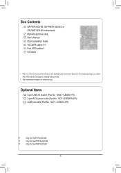
Box Contents GA-P67A-UD3-B3, GA-PH67A-UD3-B3, or GA-PH67-UD3-B3 motherboard Motherboard driver disk User's Manual Quick Installation Guide Two SATA cableskl Four SATA cablesj I/O Shield • The box contents above are subject to change without notice. • The motherboard image is for reference only. Optional Items 2-port USB 2.0 bracket (Part No. 12CR1-1UB030-5*R) 2-port SATA power cable (Part...
Box Contents GA-P67A-UD3-B3, GA-PH67A-UD3-B3, or GA-PH67-UD3-B3 motherboard Motherboard driver disk User's Manual Quick Installation Guide Two SATA cableskl Four SATA cablesj I/O Shield • The box contents above are subject to change without notice. • The motherboard image is for reference only. Optional Items 2-port USB 2.0 bracket (Part No. 12CR1-1UB030-5*R) 2-port SATA power cable (Part...
Manual
Page 7
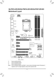
GA-P67A-UD3-B3/GA-PH67A-UD3-B3/GA-PH67-UD3-B3 Motherboard Layout KB_MS_USB R_SPDIF ATX_12V_2X4 R_USB_2 LGA1155 PHASE LED R_USB_1 R_USB30 ATX USB_LAN Renesas D720200jk AUDIO Realtek RTL8111E CODEC SPDIF_O iTE IT8728 F_AUDIO SYS_FAN1 PCIEX1_1 (Note) BAT CPU_FAN PCIEX16 GA-P67A-UD3-B3/GA-PH67A-UD3-B3/ GA-PH67-UD3-B3 DDR3_1 DDR3_2 DDR3_3 DDR3_4 PCIEX1_2 PCIEX1_3 PCIEX4 PCI1 PCI2 F_USB2 Intel® P67j M_BIOS B_BIOS Intel® H67kl SATA3_0...
GA-P67A-UD3-B3/GA-PH67A-UD3-B3/GA-PH67-UD3-B3 Motherboard Layout KB_MS_USB R_SPDIF ATX_12V_2X4 R_USB_2 LGA1155 PHASE LED R_USB_1 R_USB30 ATX USB_LAN Renesas D720200jk AUDIO Realtek RTL8111E CODEC SPDIF_O iTE IT8728 F_AUDIO SYS_FAN1 PCIEX1_1 (Note) BAT CPU_FAN PCIEX16 GA-P67A-UD3-B3/GA-PH67A-UD3-B3/ GA-PH67-UD3-B3 DDR3_1 DDR3_2 DDR3_3 DDR3_4 PCIEX1_2 PCIEX1_3 PCIEX4 PCI1 PCI2 F_USB2 Intel® P67j M_BIOS B_BIOS Intel® H67kl SATA3_0...
Manual
Page 8
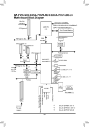
GA-P67A-UD3-B3/GA-PH67A-UD3-B3/GA-PH67-UD3-B3 Motherboard Block Diagram PCIe CLK (100 MHz) 1 PCI Express x16 LGA1155 CPU CPU CLK+/- (100 MHz) DDR3 2133/1866/1600/1333/1066 MHzj DDR3 1333/1066/.../Mouse Surround Speaker Out Center/Subwoofer Speaker Out Side Speaker Out MIC Line Out Line In S/PDIF Out 2 PCI PCI CLK (33 MHz) j k l Only for GA-P67A-UD3-B3 Only for GA-PH67A-UD3-B3 Only for GA-PH67-UD3-B3 - 8 -
GA-P67A-UD3-B3/GA-PH67A-UD3-B3/GA-PH67-UD3-B3 Motherboard Block Diagram PCIe CLK (100 MHz) 1 PCI Express x16 LGA1155 CPU CPU CLK+/- (100 MHz) DDR3 2133/1866/1600/1333/1066 MHzj DDR3 1333/1066/.../Mouse Surround Speaker Out Center/Subwoofer Speaker Out Side Speaker Out MIC Line Out Line In S/PDIF Out 2 PCI PCI CLK (33 MHz) j k l Only for GA-P67A-UD3-B3 Only for GA-PH67A-UD3-B3 Only for GA-PH67-UD3-B3 - 8 -
Manual
Page 9
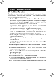
...for warranty validation. • Always remove the AC power by your hardware components are connected tightly and securely. • When handling the motherboard, avoid touching any installation steps or have a problem related to the local voltage standard. • Before using the product, please verify...; Prior to come in a high-temperature environment. • Turning on the computer power during the installation process can become damaged as a motherboard, CPU or memory. ponents such as a result of an antistatic pad or within the computer casing. • Do not place the computer...
...for warranty validation. • Always remove the AC power by your hardware components are connected tightly and securely. • When handling the motherboard, avoid touching any installation steps or have a problem related to the local voltage standard. • Before using the product, please verify...; Prior to come in a high-temperature environment. • Turning on the computer power during the installation process can become damaged as a motherboard, CPU or memory. ponents such as a result of an antistatic pad or within the computer casing. • Do not place the computer...
Manual
Page 12
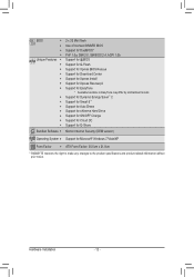
... Charge Support for Cloud OC Support for Q-Share Norton Internet Security (OEM version) Operating System w Support for EasyTune * Available functions in EasyTune may differ by motherboard model.
... Charge Support for Cloud OC Support for Q-Share Norton Internet Security (OEM version) Operating System w Support for EasyTune * Available functions in EasyTune may differ by motherboard model.
Manual
Page 13
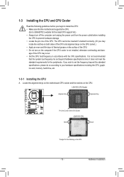
...Go to your hardware specifications including the CPU, graphics card, memory, hard drive, etc. 1-3-1 Installing the CPU A. Locate the alignment keys on the motherboard CPU socket and the notches on the CPU - 13 - If you may occur. • Set the CPU host frequency in accordance with the ... system bus frequency be inserted if oriented incorrectly. (Or you wish to set beyond the standard specifications, please do so according to GIGABYTE's website for the peripherals. LGA1155 CPU Socket Alignment Key Alignment Key Pin One Corner of the CPU may locate the notches on both...
...Go to your hardware specifications including the CPU, graphics card, memory, hard drive, etc. 1-3-1 Installing the CPU A. Locate the alignment keys on the motherboard CPU socket and the notches on the CPU - 13 - If you may occur. • Set the CPU host frequency in accordance with the ... system bus frequency be inserted if oriented incorrectly. (Or you wish to set beyond the standard specifications, please do so according to GIGABYTE's website for the peripherals. LGA1155 CPU Socket Alignment Key Alignment Key Pin One Corner of the CPU may locate the notches on both...
Manual
Page 14
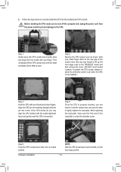
... one corner of the CPU socket (or you may align the CPU notches with the socket alignment keys) and gently insert the CPU into the motherboard CPU socket. Align the CPU pin one marking (triangle) with the pin one hand to hold the socket lever and use your thumb to lift...
... one corner of the CPU socket (or you may align the CPU notches with the socket alignment keys) and gently insert the CPU into the motherboard CPU socket. Align the CPU pin one marking (triangle) with the pin one hand to hold the socket lever and use your thumb to lift...
Manual
Page 15
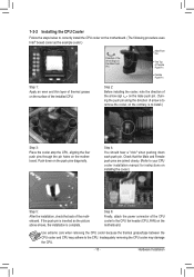
... the CPU cooler may adhere to the CPU. 1-3-2 Installing the CPU Cooler Follow the steps below to correctly install the CPU cooler on the motherboard. (The following procedure uses Intel® boxed cooler as the picture above shows, the installation is to install.) Step 3: Place the cooler ...Refer to your CPU cooler installation manual for instructions on the surface of the CPU cooler to the CPU fan header (CPU_FAN) on the motherboard. Hardware Installation Use extreme care when removing the CPU cooler because the thermal grease/tape between the CPU cooler and CPU may damage the...
... the CPU cooler may adhere to the CPU. 1-3-2 Installing the CPU Cooler Follow the steps below to correctly install the CPU cooler on the motherboard. (The following procedure uses Intel® boxed cooler as the picture above shows, the installation is to install.) Step 3: Place the cooler ...Refer to your CPU cooler installation manual for instructions on the surface of the CPU cooler to the CPU fan header (CPU_FAN) on the motherboard. Hardware Installation Use extreme care when removing the CPU cooler because the thermal grease/tape between the CPU cooler and CPU may damage the...
Manual
Page 16
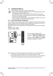
DS/SS DDR3_4 - A memory module can be used . (Go to GIGABYTE's website for optimum performance. After the memory is recommended that memory of the same capacity, brand, speed, and chips be installed in Dual... as following guidelines before installing the memory in only one DDR3 memory module is recommended that memory of the memory. Dual Channel Memory Configuration This motherboard provides four DDR3 memory sockets and supports Dual Channel Technology. Hardware Installation - 16 - 1-4 Installing the Memory 1-4-1 Read the following : Channel 0: DDR3_1, DDR3_2 ...
DS/SS DDR3_4 - A memory module can be used . (Go to GIGABYTE's website for optimum performance. After the memory is recommended that memory of the same capacity, brand, speed, and chips be installed in Dual... as following guidelines before installing the memory in only one DDR3 memory module is recommended that memory of the memory. Dual Channel Memory Configuration This motherboard provides four DDR3 memory sockets and supports Dual Channel Technology. Hardware Installation - 16 - 1-4 Installing the Memory 1-4-1 Read the following : Channel 0: DDR3_1, DDR3_2 ...
Manual
Page 17
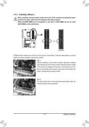
.... As indicated in one direction. Hardware Installation Step 1: Note the orientation of the memory socket. Follow the steps below to install DDR3 DIMMs on this motherboard. Place the memory module on the memory and insert it can only fit in the picture on the left, place your memory modules in the...
.... As indicated in one direction. Hardware Installation Step 1: Note the orientation of the memory socket. Follow the steps below to install DDR3 DIMMs on this motherboard. Place the memory module on the memory and insert it can only fit in the picture on the left, place your memory modules in the...
Manual
Page 18
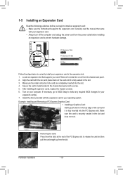
... turn off the computer and unplug the power cord from the power outlet before you begin to install an expansion card: • Make sure the motherboard supports the expansion card. Turn on the top edge of the PCI Express slot to release the card and then pull the card straight up...
... turn off the computer and unplug the power cord from the power outlet before you begin to install an expansion card: • Make sure the motherboard supports the expansion card. Turn on the top edge of the PCI Express slot to release the card and then pull the card straight up...
Manual
Page 19
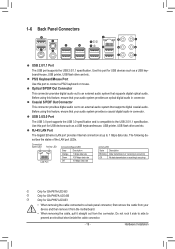
...not rock it side to side to a back panel connector, first remove the cable from your device and then remove it from the motherboard. • When removing the cable, pull it straight out from the connector. Use this port for USB devices such as a ... USB 2.0/1.1 specification. USB 3.0/2.0 Port The USB 3.0 port supports the USB 3.0 specification and is occurring j k l Only for GA-P67A-UD3-B3 Only for GA-PH67A-UD3-B3 Only for GA-PH67-UD3-B3 • When removing the cable connected to prevent an electrical short inside the cable connector. - 19 - The following describes the ...
...not rock it side to side to a back panel connector, first remove the cable from your device and then remove it from the motherboard. • When removing the cable, pull it straight out from the connector. Use this port for USB devices such as a ... USB 2.0/1.1 specification. USB 3.0/2.0 Port The USB 3.0 port supports the USB 3.0 specification and is occurring j k l Only for GA-P67A-UD3-B3 Only for GA-PH67A-UD3-B3 Only for GA-PH67-UD3-B3 • When removing the cable connected to prevent an electrical short inside the cable connector. - 19 - The following describes the ...
Manual
Page 21
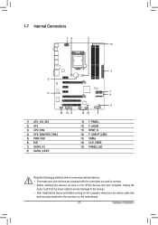
..., make sure your devices are compliant with the connectors you wish to connect. • Before installing the devices, be sure to the connector on the motherboard. - 21 - Hardware Installation Unplug the power cord from the power outlet to prevent damage to the devices. • After installing the device and before connecting...
..., make sure your devices are compliant with the connectors you wish to connect. • Before installing the devices, be sure to the connector on the motherboard. - 21 - Hardware Installation Unplug the power cord from the power outlet to prevent damage to the devices. • After installing the device and before connecting...
Manual
Page 22
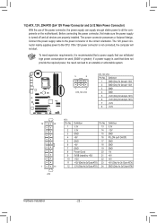
... possesses a foolproof design. Connect the power supply cable to the CPU. If the 12V power connector is turned off and all the components on the motherboard. If a power supply is recommended that a power supply that can withstand high power consumption be used that does not provide the required power, the result...
... possesses a foolproof design. Connect the power supply cable to the CPU. If the 12V power connector is turned off and all the components on the motherboard. If a power supply is recommended that a power supply that can withstand high power consumption be used that does not provide the required power, the result...
Manual
Page 23
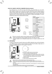
...battery, note the orientation of the positive side (+) and the negative side (-) of a CPU fan with local environmental regulations. - 23 - The motherboard supports CPU fan speed control, which requires the use a metal object like a screwdriver to the CPU or the system may be handled in the...; Used batteries must be lost. You may clear the CMOS values by yourself or uncertain about the bat- 3/4/5) CPU_FAN/SYS_FAN1/SYS_FAN2/PWR_FAN (Fan Headers) The motherboard has a 4-pin CPU fan header (CPU_FAN), a 4-pin (SYS_FAN2) and a 3-pin (SYS_ FAN1) system fan headers, and a 3-pin power fan ...
...battery, note the orientation of the positive side (+) and the negative side (-) of a CPU fan with local environmental regulations. - 23 - The motherboard supports CPU fan speed control, which requires the use a metal object like a screwdriver to the CPU or the system may be handled in the...; Used batteries must be lost. You may clear the CMOS values by yourself or uncertain about the bat- 3/4/5) CPU_FAN/SYS_FAN1/SYS_FAN2/PWR_FAN (Fan Headers) The motherboard has a 4-pin CPU fan header (CPU_FAN), a 4-pin (SYS_FAN2) and a 3-pin (SYS_ FAN1) system fan headers, and a 3-pin power fan ...

Manual
Page 26
...back panel audio connections simultane- If you wish to connect an HDMI display to the graphics card and have digital audio output from your motherboard to Chapter 5, "Configuring 2/4/5.1/7.1-Channel Audio." • Some chassis provide a front panel audio module that has different wire assignments, please ...connectors on both of a single plug. Definition 1 SPDIFO 1 2 GND Hardware Installation - 26 - Make sure the wire assignments of the motherboard header. If your graphics card if you want to mute the back panel audio (only supported when using an HD front panel audio module...
...back panel audio connections simultane- If you wish to connect an HDMI display to the graphics card and have digital audio output from your motherboard to Chapter 5, "Configuring 2/4/5.1/7.1-Channel Audio." • Some chassis provide a front panel audio module that has different wire assignments, please ...connectors on both of a single plug. Definition 1 SPDIFO 1 2 GND Hardware Installation - 26 - Make sure the wire assignments of the motherboard header. If your graphics card if you want to mute the back panel audio (only supported when using an HD front panel audio module...


