
Manual
Page 1
... the RAID-ready system drive. (To add a new hard drive into the array to individually install the X.H.D utility later. Using GIGABYTE eXtreme Hard Drive (X.H.D) Instructions:(Note 2) Before launching X.H.D, make sure the new drive is recommended that already exists, users also can ...B. Or you have to enhance your needs and hardware components. 3. To manually set up all motherboard drivers, including the X.H.D utility. eXtreme Hard Drive (X.H.D) With GIGABYTE eXtreme Hard Drive (X.H.D)(Note 1), users can quickly configure a RAIDready system for complex and time-consuming configurations....
... the RAID-ready system drive. (To add a new hard drive into the array to individually install the X.H.D utility later. Using GIGABYTE eXtreme Hard Drive (X.H.D) Instructions:(Note 2) Before launching X.H.D, make sure the new drive is recommended that already exists, users also can ...B. Or you have to enhance your needs and hardware components. 3. To manually set up all motherboard drivers, including the X.H.D utility. eXtreme Hard Drive (X.H.D) With GIGABYTE eXtreme Hard Drive (X.H.D)(Note 1), users can quickly configure a RAIDready system for complex and time-consuming configurations....
Manual
Page 1
GA-P55A-UD7 LGA1156 socket motherboard for Intel® Core™ i7 processor family/ Intel® Core™ i5 processor family/Intel® Core™ i3 processor family User's Manual Rev. 1001 12ME-P55AUD7-1001R
GA-P55A-UD7 LGA1156 socket motherboard for Intel® Core™ i7 processor family/ Intel® Core™ i5 processor family/Intel® Core™ i3 processor family User's Manual Rev. 1001 12ME-P55AUD7-1001R
Manual
Page 2
Motherboard GA-P55A-UD7 Jan. 26, 2010 Motherboard GA-P55A-UD7 Jan. 26, 2010
Motherboard GA-P55A-UD7 Jan. 26, 2010 Motherboard GA-P55A-UD7 Jan. 26, 2010
Manual
Page 3
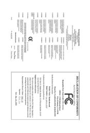
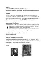
..., transmitted, or published in this manual may be made by GIGABYTE without GIGABYTE's prior written permission. Check your motherboard looks like this product, GIGABYTE provides the following types of documentations: For quick set-up of GIGABYTE. For instructions on how to their respective owners. For product-...related information, check on our website at: http://www.gigabyte.com.tw Identifying Your Motherboard Revision The revision number on our website. Changes to assist in this manual is protected by any form...
..., transmitted, or published in this manual may be made by GIGABYTE without GIGABYTE's prior written permission. Check your motherboard looks like this product, GIGABYTE provides the following types of documentations: For quick set-up of GIGABYTE. For instructions on how to their respective owners. For product-...related information, check on our website at: http://www.gigabyte.com.tw Identifying Your Motherboard Revision The revision number on our website. Changes to assist in this manual is protected by any form...
Manual
Page 4
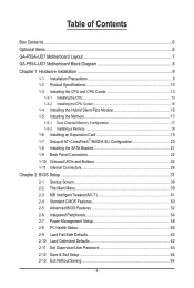
Table of Contents Box Contents...6 Optional Items...6 GA-P55A-UD7 Motherboard Layout 7 GA-P55A-UD7 Motherboard Block Diagram 8 Chapter 1 Hardware Installation 9 1-1 Installation Precautions 9 1-2 Product Specifications 10 1-3 Installing the CPU and CPU Cooler 13 1-3-1 Installing the CPU 13 1-3-2 Installing the CPU Cooler ...
Table of Contents Box Contents...6 Optional Items...6 GA-P55A-UD7 Motherboard Layout 7 GA-P55A-UD7 Motherboard Block Diagram 8 Chapter 1 Hardware Installation 9 1-1 Installation Precautions 9 1-2 Product Specifications 10 1-3 Installing the CPU and CPU Cooler 13 1-3-1 Installing the CPU 13 1-3-2 Installing the CPU Cooler ...
Manual
Page 6
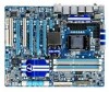
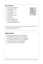
... SATA power cable (Part No. 12CF1-2SERPW-0*R) S/PDIF In cable (Part No. 12CR1-1SPDIN-0*R) COM port cable (Part No. 12CF1-1CM001-3*R) - 6 - Box Contents GA-P55A-UD7 motherboard Motherboard driver disk User's Manual Quick Installation Guide One IDE cable Four SATA 3Gb/s cables I/O Shield One SATA bracket 2-Way SLI bridge connector 3-Way SLI bridge... connector One Hybrid Silent-Pipe module kit • The box contents above are subject to change without notice. • The motherboard image is for reference only and the actual items shall depend on the product package you obtain.
... SATA power cable (Part No. 12CF1-2SERPW-0*R) S/PDIF In cable (Part No. 12CR1-1SPDIN-0*R) COM port cable (Part No. 12CF1-1CM001-3*R) - 6 - Box Contents GA-P55A-UD7 motherboard Motherboard driver disk User's Manual Quick Installation Guide One IDE cable Four SATA 3Gb/s cables I/O Shield One SATA bracket 2-Way SLI bridge connector 3-Way SLI bridge... connector One Hybrid Silent-Pipe module kit • The box contents above are subject to change without notice. • The motherboard image is for reference only and the actual items shall depend on the product package you obtain.
Manual
Page 7
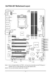
...GA-P55A-UD7 Motherboard Layout KB_USB R_SPDIF SYS_FAN3 ATX_12V_2X USB_1394_ESATA_2 USB_1394_ESATA_1 USB_LAN LGA1156 CPU_FAN PW_SW ATX M_P_LED V_P_LED PWR_FAN USB30_LAN AUDIO JMicron JMB362 NEC D720200F1 F_AUDIO PCIEX1_1 (Note 1) RTL8111D PCH_FAN RTL8111D NF200 PEX8608 Bridge PCIEX16_1 DDR3_2 DDR3_1 DDR3_4 DDR3_3 PHASE LED GIGABYTE... SATA2 IDE GSATA2_7 GSATA2_6 PCIEX8_1 SATA2_1 SATA2_0 CODEC CD_IN SPDIF_I PCIEX16_2 PCI1 SPDIF_O PCIEX8_2GA-P55A-UD7 B_BIOS Intel® P55 M_BIOS TSB43AB23 S4_S5_LED S3_LED...
...GA-P55A-UD7 Motherboard Layout KB_USB R_SPDIF SYS_FAN3 ATX_12V_2X USB_1394_ESATA_2 USB_1394_ESATA_1 USB_LAN LGA1156 CPU_FAN PW_SW ATX M_P_LED V_P_LED PWR_FAN USB30_LAN AUDIO JMicron JMB362 NEC D720200F1 F_AUDIO PCIEX1_1 (Note 1) RTL8111D PCH_FAN RTL8111D NF200 PEX8608 Bridge PCIEX16_1 DDR3_2 DDR3_1 DDR3_4 DDR3_3 PHASE LED GIGABYTE... SATA2 IDE GSATA2_7 GSATA2_6 PCIEX8_1 SATA2_1 SATA2_0 CODEC CD_IN SPDIF_I PCIEX16_2 PCI1 SPDIF_O PCIEX8_2GA-P55A-UD7 B_BIOS Intel® P55 M_BIOS TSB43AB23 S4_S5_LED S3_LED...
Manual
Page 8
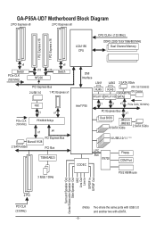
GA-P55A-UD7 Motherboard Block Diagram 2 PCI Express x8 2 PCI Express x8 LGA1156 CPU CPU CLK+/- (133 MHz) DDR3 2200/1333/1066/800 MHz Dual Channel Memory 1 PCI Express ... PCI Express Bus Marvell 9128 2 SATA 6Gb/s PCI Bus TSB43AB23 3 IEEE 1394a DMI Interface LAN1 LAN2 2 SATA 3Gb/s RJ45 ATA-133/100/66/33 RJ45 GIGABYTE IDE Channel RTL8111D RTL8111D SATA2 Intel® P55 x1 x1 x1 PCIe CLK (100 MHz) PCI Express Bus x1 Dual BIOS JMicron JMB362 6 SATA 3Gb...
GA-P55A-UD7 Motherboard Block Diagram 2 PCI Express x8 2 PCI Express x8 LGA1156 CPU CPU CLK+/- (133 MHz) DDR3 2200/1333/1066/800 MHz Dual Channel Memory 1 PCI Express ... PCI Express Bus Marvell 9128 2 SATA 6Gb/s PCI Bus TSB43AB23 3 IEEE 1394a DMI Interface LAN1 LAN2 2 SATA 3Gb/s RJ45 ATA-133/100/66/33 RJ45 GIGABYTE IDE Channel RTL8111D RTL8111D SATA2 Intel® P55 x1 x1 x1 PCIe CLK (100 MHz) PCI Express Bus x1 Dual BIOS JMicron JMB362 6 SATA 3Gb...

Manual
Page 9
... an electrostatic shielding container. • Before unplugging the power supply cable from the power outlet before installing or removing the motherboard or other hardware components. • When connecting hardware components to the internal connectors on the computer power during the installation ...have an ESD wrist strap, keep your hands dry and first touch a metal object to eliminate static electricity. • Prior to installing the motherboard, please have a problem related to the use of the product, please consult a certified computer technician. - 9 - ponents such as a result...
... an electrostatic shielding container. • Before unplugging the power supply cable from the power outlet before installing or removing the motherboard or other hardware components. • When connecting hardware components to the internal connectors on the computer power during the installation ...have an ESD wrist strap, keep your hands dry and first touch a metal object to eliminate static electricity. • Prior to installing the motherboard, please have a problem related to the use of the product, please consult a certified computer technician. - 9 - ponents such as a result...

Manual
Page 12
... two with eSATA. (Note 5) Whether the CPU/system fan speed control function is recommended that you install. (Note 6) Available functions in EasyTune may differ by motherboard model. I/O Controller w Hardware Monitor w w w w w w BIOS w w w w Unique Features w w w w w w w w w w w w Bundled Software w iTE IT8720 chip System voltage detection CPU/System temperature detection CPU/System/Power fan speed detection...
... two with eSATA. (Note 5) Whether the CPU/system fan speed control function is recommended that you install. (Note 6) Available functions in EasyTune may differ by motherboard model. I/O Controller w Hardware Monitor w w w w w w BIOS w w w w Unique Features w w w w w w w w w w w w Bundled Software w iTE IT8720 chip System voltage detection CPU/System temperature detection CPU/System/Power fan speed detection...

Manual
Page 13
.... 1-3-1 Installing the CPU A. age of the CPU Socket LGA1156 CPU Notch Notch Triangle Pin One Marking on the CPU. Locate the alignment keys on the motherboard CPU socket and the notches on the CPU - 13 - Hardware Installation 1-3 Installing the CPU and CPU Cooler Read the following guidelines before installing the CPU... meet the standard requirements for the latest CPU support list.) • Always turn on the computer if the CPU cooler is not recommended that the motherboard supports the CPU. (Go to GIGABYTE's website for the peripherals.
.... 1-3-1 Installing the CPU A. age of the CPU Socket LGA1156 CPU Notch Notch Triangle Pin One Marking on the CPU. Locate the alignment keys on the motherboard CPU socket and the notches on the CPU - 13 - Hardware Installation 1-3 Installing the CPU and CPU Cooler Read the following guidelines before installing the CPU... meet the standard requirements for the latest CPU support list.) • Always turn on the computer if the CPU cooler is not recommended that the motherboard supports the CPU. (Go to GIGABYTE's website for the peripherals.

Manual
Page 14
... your index finger down and away from the power outlet to prevent damage to the CPU. Step 5: Push the CPU socket lever back into the motherboard CPU socket. Hardware Installation - 14 - Align the CPU pin one marking (triangle) with your thumb and index fingers. Before installing the CPU, make sure the...
... your index finger down and away from the power outlet to prevent damage to the CPU. Step 5: Push the CPU socket lever back into the motherboard CPU socket. Hardware Installation - 14 - Align the CPU pin one marking (triangle) with your thumb and index fingers. Before installing the CPU, make sure the...

Manual
Page 15
... down each push pin. Check that the Male and Female push pins are joined closely. (Refer to correctly install the CPU cooler on the motherboard. (The following procedure uses Intel® boxed cooler as the picture above shows, the installation is to the CPU. Inadequately removing the CPU... sign on the male push pin. (Turning the push pin along the direction of arrow is to the CPU fan header (CPU_FAN) on the motherboard. 1-3-2 Installing the CPU Cooler Follow the steps below to your CPU cooler installation manual for instructions on installing the cooler.) Step 5: After the ...
... down each push pin. Check that the Male and Female push pins are joined closely. (Refer to correctly install the CPU cooler on the motherboard. (The following procedure uses Intel® boxed cooler as the picture above shows, the installation is to the CPU. Inadequately removing the CPU... sign on the male push pin. (Turning the push pin along the direction of arrow is to the CPU fan header (CPU_FAN) on the motherboard. 1-3-2 Installing the CPU Cooler Follow the steps below to your CPU cooler installation manual for instructions on installing the cooler.) Step 5: After the ...

Manual
Page 16
... Hybrid Silent-Pipe Follow the steps below to install the Hybrid Silent-Pipe module: Step 1: Unfasten the diagonally placed screws from the waterblock on the motherboard, be sure to connect it before installing the Hybrid Silent-Pipe module to avoid interference. A Philip's screwdriver 2. Step 4: Secure the heatsink using the included screws...
... Hybrid Silent-Pipe Follow the steps below to install the Hybrid Silent-Pipe module: Step 1: Unfasten the diagonally placed screws from the waterblock on the motherboard, be sure to connect it before installing the Hybrid Silent-Pipe module to avoid interference. A Philip's screwdriver 2. Step 4: Secure the heatsink using the included screws...

Manual
Page 17
...Configurations Table DDR3_2 DDR3_1 DDR3_4 DDR3_3 Two Modules - - When enabling Dual Channel mode with two memory modules, be used . (Go to GIGABYTE's website for optimum performance. If only one DDR3 memory module is recommended that memory of the same capacity, brand, speed, and chips... only one DDR3 memory module is installed, be sure to insert the memory, switch the direction. 1-5-1 Dual Channel Memory Configuration This motherboard provides four DDR3 memory sockets and supports Dual Channel Technology. A memory module can be used for the latest memory support list.) &#...
...Configurations Table DDR3_2 DDR3_1 DDR3_4 DDR3_3 Two Modules - - When enabling Dual Channel mode with two memory modules, be used . (Go to GIGABYTE's website for optimum performance. If only one DDR3 memory module is recommended that memory of the same capacity, brand, speed, and chips... only one DDR3 memory module is installed, be sure to insert the memory, switch the direction. 1-5-1 Dual Channel Memory Configuration This motherboard provides four DDR3 memory sockets and supports Dual Channel Technology. A memory module can be used for the latest memory support list.) &#...

Manual
Page 18
..., make sure to turn off the computer and unplug the power cord from the power outlet to prevent damage to install DDR3 DIMMs on this motherboard. Follow the steps below to correctly install your fingers on the top edge of the memory module. Place the memory module on the memory and...
..., make sure to turn off the computer and unplug the power cord from the power outlet to prevent damage to install DDR3 DIMMs on this motherboard. Follow the steps below to correctly install your fingers on the top edge of the memory module. Place the memory module on the memory and...
Manual
Page 19
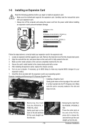
... on the card are completely inserted into the PCI Express slot. Secure the card's metal bracket to install an expansion card: • Make sure the motherboard supports the expansion card. Hardware Installation
... on the card are completely inserted into the PCI Express slot. Secure the card's metal bracket to install an expansion card: • Make sure the motherboard supports the expansion card. Hardware Installation
Manual
Page 20
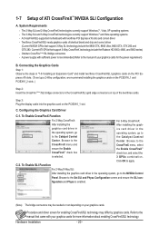
... Ultra, 9800 GTX, GTX 260 and GTX 280. The 2-Way SLI and 2-Way CrossFireX technologies currently support Windows 7, Vista, XP operating systems - A CrossFireX/SLI-supported motherboard with your graphics cards for enabling CrossFireX/SLI technology may be needed or not depending on your graphics cards. Current ATI GPUs that came with...
... Ultra, 9800 GTX, GTX 260 and GTX 280. The 2-Way SLI and 2-Way CrossFireX technologies currently support Windows 7, Vista, XP operating systems - A CrossFireX/SLI-supported motherboard with your graphics cards for enabling CrossFireX/SLI technology may be needed or not depending on your graphics cards. Current ATI GPUs that came with...

Manual
Page 21
... SATA Connector The SATA bracket includes one SATA bracket, one SATA signal cable, and one free PCI slot and secure the SATA bracket to your motherboard. Step 4: Plug one end of the SATA signal cable into the corresponding connectors when installing. Then attach the SATA power cable to the SATA port...
... SATA Connector The SATA bracket includes one SATA bracket, one SATA signal cable, and one free PCI slot and secure the SATA bracket to your motherboard. Step 4: Plug one end of the SATA signal cable into the corresponding connectors when installing. Then attach the SATA power cable to the SATA port...

Manual
Page 22
... This connector provides digital audio out to connect an external SATA device; Use this feature, ensure that your device and then remove it from the motherboard. • When removing the cable, pull it side to side to an external audio system that supports digital optical audio. Use the port to an...
... This connector provides digital audio out to connect an external SATA device; Use this feature, ensure that your device and then remove it from the motherboard. • When removing the cable, pull it side to side to an external audio system that supports digital optical audio. Use the port to an...


