Manual
Page 11
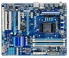
...panel, 4 via the USB brackets connected to the internal USB headers) j - k Only for P55 Chipset. Up to the internal USB headers) k NEC chip: - USB ...x CD In connector w 1 x S/PDIF In header w 1 x S/PDIF Out header w 2 x USB 2.0/1.1 headers w 1 x serial port header w 1 x parallel port header w 1 x clearing CMOS jumper Back Panel w 1 x PS/2 keyboard or PS/2 mouse port Connectors w 1 x coaxial S/PDIF Out connector w 1 x optical S/PDIF Out connector w 8 x USB 2.0/1.1 ports j w ...
...panel, 4 via the USB brackets connected to the internal USB headers) j - k Only for P55 Chipset. Up to the internal USB headers) k NEC chip: - USB ...x CD In connector w 1 x S/PDIF In header w 1 x S/PDIF Out header w 2 x USB 2.0/1.1 headers w 1 x serial port header w 1 x parallel port header w 1 x clearing CMOS jumper Back Panel w 1 x PS/2 keyboard or PS/2 mouse port Connectors w 1 x coaxial S/PDIF Out connector w 1 x optical S/PDIF Out connector w 8 x USB 2.0/1.1 ports j w ...
Manual
Page 25
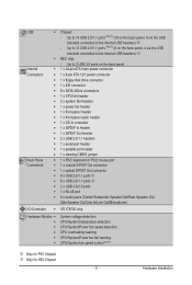
...; Used batteries must be lost. Replace the battery when the battery voltage drops to a low level, or the CMOS values may not be accurate or may clear the CMOS values by yourself or uncertain about the battery model. • When installing the battery, note the orientation of the... • Replace the battery with SATA 1.5Gb/s standard. Gently remove the battery from the battery holder and wait for one . Hardware Installation The GIGABYTE SATA2 controller supports RAID 0, RAID 1, and JBOD. You may be an even number. Each SATA connector supports a single SATA device. Replace the ...
...; Used batteries must be lost. Replace the battery when the battery voltage drops to a low level, or the CMOS values may not be accurate or may clear the CMOS values by yourself or uncertain about the battery model. • When installing the battery, note the orientation of the... • Replace the battery with SATA 1.5Gb/s standard. Gently remove the battery from the battery holder and wait for one . Hardware Installation The GIGABYTE SATA2 controller supports RAID 0, RAID 1, and JBOD. You may be an even number. Each SATA connector supports a single SATA device. Replace the ...

Manual
Page 30
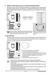
... 8 NCTS- 9 NRI- 10 No Pin 19) CLR_CMOS (Clearing CMOS Jumper) Use this jumper to factory defaults. Hardware Installation - 30 - date information and BIOS configurations) and reset the CMOS values to clear the CMOS values (e.g. Pin No. To clear the CMOS values, place a jumper cap on your computer and unplug the... power cord from the jumper. Open: Normal Short: Clear CMOS Values • Always turn off your...
... 8 NCTS- 9 NRI- 10 No Pin 19) CLR_CMOS (Clearing CMOS Jumper) Use this jumper to factory defaults. Hardware Installation - 30 - date information and BIOS configurations) and reset the CMOS values to clear the CMOS values (e.g. Pin No. To clear the CMOS values, place a jumper cap on your computer and unplug the... power cord from the jumper. Open: Normal Short: Clear CMOS Values • Always turn off your...
Manual
Page 33
...BIOS Setup program. To see more advanced BIOS Setup menu options, you not flash the BIOS. To upgrade the BIOS, use either the GIGABYTE Q-Flash or @BIOS utility. • Q-Flash allows the user to keep the configuration values in Chapter 1 for the beep codes description....Internet and updates the BIOS. When the power is turned off, the battery on using the current version of the battery/ clearing CMOS jumper in the CMOS. Refer to Chapter 5, "Troubleshooting," for how to prevent system instability or other unexpected results. Inadequately altering the settings may ...
...BIOS Setup program. To see more advanced BIOS Setup menu options, you not flash the BIOS. To upgrade the BIOS, use either the GIGABYTE Q-Flash or @BIOS utility. • Q-Flash allows the user to keep the configuration values in Chapter 1 for the beep codes description....Internet and updates the BIOS. When the power is turned off, the battery on using the current version of the battery/ clearing CMOS jumper in the CMOS. Refer to Chapter 5, "Troubleshooting," for how to prevent system instability or other unexpected results. Inadequately altering the settings may ...
Manual
Page 37
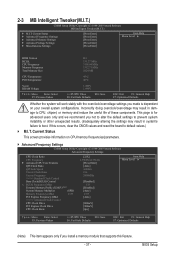
... the useful life of these components. Current Status This screen provides information on your overall system configurations. If this feature. - 37 - 2-3 MB Intelligent Tweaker(M.I.T.) CMOS Setup Utility-Copyright (C) 1984-2009 Award Software MB Intelligent Tweaker(M.I.T.) } M.I .T. BIOS Setup Incorrectly doing overclock/overvoltage may result in system's failure to default values... the overclock/overvoltage settings you made is for advanced users only and we recommend you install a memory module that supports this occurs, clear the CMOS values and reset the board to boot.
... the useful life of these components. Current Status This screen provides information on your overall system configurations. If this feature. - 37 - 2-3 MB Intelligent Tweaker(M.I.T.) CMOS Setup Utility-Copyright (C) 1984-2009 Award Software MB Intelligent Tweaker(M.I.T.) } M.I .T. BIOS Setup Incorrectly doing overclock/overvoltage may result in system's failure to default values... the overclock/overvoltage settings you made is for advanced users only and we recommend you install a memory module that supports this occurs, clear the CMOS values and reset the board to boot.
Manual
Page 39
... chipset detects that supports this set the QPI clock ratio. When enabled, the CPU core frequency and voltage will allow for automated system reboot, or clear the CMOS values to reset the board to default values. (Default: Disabled) (Note) This item is present only if you install a CPU that an overheating is...
... chipset detects that supports this set the QPI clock ratio. When enabled, the CPU core frequency and voltage will allow for automated system reboot, or clear the CMOS values to reset the board to default values. (Default: Disabled) (Note) This item is present only if you install a CPU that an overheating is...
Manual
Page 55
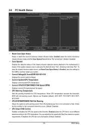
...Sets the warning threshold for CPU temperature. BIOS Setup Options are: Disabled (default), 60oC/140oF, 70oC/158oF, 80oC/176oF, 90oC/194oF. Enabled clears the record of previous chassis intrusion status and the Case Opened field will show "No" at full speed. (Default: Enabled) - 55 -...of previous chassis intrusion status. Enabled allows the CPU fan to run at different speed according to the CMOS, and then restart your system. 2-8 PC Health Status CMOS Setup Utility-Copyright (C) 1984-2009 Award Software PC Health Status Reset Case Open Status Case Opened Vcore ...
...Sets the warning threshold for CPU temperature. BIOS Setup Options are: Disabled (default), 60oC/140oF, 70oC/158oF, 80oC/176oF, 90oC/194oF. Enabled clears the record of previous chassis intrusion status and the Case Opened field will show "No" at full speed. (Default: Enabled) - 55 -...of previous chassis intrusion status. Enabled allows the CPU fan to run at different speed according to the CMOS, and then restart your system. 2-8 PC Health Status CMOS Setup Utility-Copyright (C) 1984-2009 Award Software PC Health Status Reset Case Open Status Case Opened Vcore ...

Manual
Page 57
... load the Optimized defaults after updating the BIOS or after clearing the CMOS values. - 57 - ENxit Setup Exit Without Saving ESC: Quit F8: Q-Flash Select Item F10: Save & Exit Setup Load Fail-Safe Defaults F11: Save CMOS to BIOS F12: Load CMOS from BIOS Press on this item and then press the key... Optimized DefaultsS(aYve/N&)?ENxit Setup Exit Without Saving ESC: Quit F8: Q-Flash Select Item F10: Save & Exit Setup Load Optimized Defaults F11: Save CMOS to BIOS F12: Load CMOS from BIOS Press on this item and then press the key to operate in optimum state. BIOS Setup
... load the Optimized defaults after updating the BIOS or after clearing the CMOS values. - 57 - ENxit Setup Exit Without Saving ESC: Quit F8: Q-Flash Select Item F10: Save & Exit Setup Load Fail-Safe Defaults F11: Save CMOS to BIOS F12: Load CMOS from BIOS Press on this item and then press the key... Optimized DefaultsS(aYve/N&)?ENxit Setup Exit Without Saving ESC: Quit F8: Q-Flash Select Item F10: Save & Exit Setup Load Optimized Defaults F11: Save CMOS to BIOS F12: Load CMOS from BIOS Press on this item and then press the key to operate in optimum state. BIOS Setup

Manual
Page 58
...make changes. In BIOS Setup, you must enter the supervisor password if you must enter the supervisor password for the password, press again. To clear the password, press on this item and type the password with up to 8 characters and then press . When the Password Check item is ... Exit Setup Exit Without Saving ESC: Quit F8: Q-Flash Select Item F10: Save & Exit Setup Change/Set/Disable Password F11: Save CMOS to BIOS F12: Load CMOS from BIOS Press on the password item and when requested for entering BIOS Setup and making BIOS changes. The message "PASSWORD DISABLED" will...
...make changes. In BIOS Setup, you must enter the supervisor password if you must enter the supervisor password for the password, press again. To clear the password, press on this item and type the password with up to 8 characters and then press . When the Password Check item is ... Exit Setup Exit Without Saving ESC: Quit F8: Q-Flash Select Item F10: Save & Exit Setup Change/Set/Disable Password F11: Save CMOS to BIOS F12: Load CMOS from BIOS Press on the password item and when requested for entering BIOS Setup and making BIOS changes. The message "PASSWORD DISABLED" will...

Manual
Page 114
... 1. Q: In the BIOS Setup program, why are hidden in Chapter 1 to short the jumper to clear the CMOS values. A: Some advanced options are some BIOS options missing? A: For motherboards that have a clearing CMOS jumper, refer to the instructions on GIGABYTE's website. eral > System). Then install the onboard HD audio driver from the motherboard driver disk...
... 1. Q: In the BIOS Setup program, why are hidden in Chapter 1 to short the jumper to clear the CMOS values. A: Some advanced options are some BIOS options missing? A: For motherboards that have a clearing CMOS jumper, refer to the instructions on GIGABYTE's website. eral > System). Then install the onboard HD audio driver from the motherboard driver disk...


