Manual
Page 5
... Contents Box Contents...7 Optional Items...7 GA-P55-UD3L-TPM/GA-P55-UD3L/GA-P55-US3L Motherboard Layout 8 Block Diagram...9 Chapter 1 Hardware Installation 11 1-1 Installation Precautions 11 1-2 Product Specifications 12 1-3 Installing the CPU and CPU Cooler 15 1-3-1 Installing the CPU 15 1-3-2 Installing the CPU Cooler 17 1-4 Installing the Memory 18 1-4-1 Dual Channel Memory Configuration 18 1-4-2 Installing a Memory 19 1-5 Installing an Expansion Card...
... Contents Box Contents...7 Optional Items...7 GA-P55-UD3L-TPM/GA-P55-UD3L/GA-P55-US3L Motherboard Layout 8 Block Diagram...9 Chapter 1 Hardware Installation 11 1-1 Installation Precautions 11 1-2 Product Specifications 12 1-3 Installing the CPU and CPU Cooler 15 1-3-1 Installing the CPU 15 1-3-2 Installing the CPU Cooler 17 1-4 Installing the Memory 18 1-4-1 Dual Channel Memory Configuration 18 1-4-2 Installing a Memory 19 1-5 Installing an Expansion Card...
Manual
Page 9
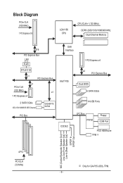
... CPU CPU CLK+/- (133 MHz) DDR3 2200/1333/1066/800 MHz Dual Channel Memory x16 PCI Express Bus LAN RJ45 RTL8111D x1 PCI Express Bus x1 PCIe CLK (...2 SATA 3Gb/s ATA-133/100/66/33 IDE Channel GIGABYTE SATA2 PCI Bus DMI Interface 1 PCI Express x4 Intel® P55 x4 PCI Express Bus Dual BIOS 6 SATA 3Gb/s 14... USB Ports CODEC LPC Bus IT8720 Floppy COM Port PS/2 KB/Mouse TPM j MIC (Center/Subwoofer Speaker Out) Line-Out (Front Speaker Out) Line-In (Rear Speaker Out) S/PDIF In S/PDIF Out 4 PCI PCI CLK (33 MHz) j Only for GA-P55-UD3L...
... CPU CPU CLK+/- (133 MHz) DDR3 2200/1333/1066/800 MHz Dual Channel Memory x16 PCI Express Bus LAN RJ45 RTL8111D x1 PCI Express Bus x1 PCIe CLK (...2 SATA 3Gb/s ATA-133/100/66/33 IDE Channel GIGABYTE SATA2 PCI Bus DMI Interface 1 PCI Express x4 Intel® P55 x4 PCI Express Bus Dual BIOS 6 SATA 3Gb/s 14... USB Ports CODEC LPC Bus IT8720 Floppy COM Port PS/2 KB/Mouse TPM j MIC (Center/Subwoofer Speaker Out) Line-Out (Front Speaker Out) Line-In (Rear Speaker Out) S/PDIF In S/PDIF Out 4 PCI PCI CLK (33 MHz) j Only for GA-P55-UD3L...
Manual
Page 11
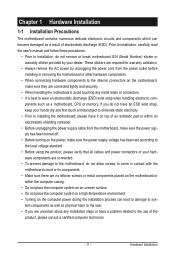
... components. • When connecting hardware components to the internal connectors on the computer power during the installation process can become damaged as a motherboard, CPU or memory.
... components. • When connecting hardware components to the internal connectors on the computer power during the installation process can become damaged as a motherboard, CPU or memory.
Manual
Page 12
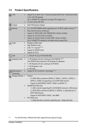
...memory (Note 1) Dual channel memory architecture Support for DDR3 2200/1333/1066/800 MHz memory modules Support for non-ECC memory modules Support for Extreme Memory Profile (XMP) memory modules (Go to GIGABYTE's website for the latest memory..., SATA2_2, SATA2_3, SATA2_4, SATA2_5) supporting up to 1 floppy disk drive "*" The GA-P55-UD3L-TPM/GA-P55-UD3L adopts All-Solid Capacitor design. Support for SATA RAID 0, RAID 1, RAID 5, and RAID 10 GIGABYTE SATA2 chip: - 1 x IDE connector supporting ATA-133/100/66/33 and up to...
...memory (Note 1) Dual channel memory architecture Support for DDR3 2200/1333/1066/800 MHz memory modules Support for non-ECC memory modules Support for Extreme Memory Profile (XMP) memory modules (Go to GIGABYTE's website for the latest memory..., SATA2_2, SATA2_3, SATA2_4, SATA2_5) supporting up to 1 floppy disk drive "*" The GA-P55-UD3L-TPM/GA-P55-UD3L adopts All-Solid Capacitor design. Support for SATA RAID 0, RAID 1, RAID 5, and RAID 10 GIGABYTE SATA2 chip: - 1 x IDE connector supporting ATA-133/100/66/33 and up to...
Manual
Page 14
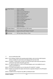
...® 7/Vista/XP Form Factor w ATX Form Factor; 30.5cm x 19.0cm j Only for GA-P55-UD3L-TPM. (Note 1) Due to Windows Vista/XP 32-bit operating system limitation, when more than 4 GB of physical memory is installed, the actual memory size displayed will be less than 4 GB. (Note 2) To enable 7.1-channel audio, you have...
...® 7/Vista/XP Form Factor w ATX Form Factor; 30.5cm x 19.0cm j Only for GA-P55-UD3L-TPM. (Note 1) Due to Windows Vista/XP 32-bit operating system limitation, when more than 4 GB of physical memory is installed, the actual memory size displayed will be less than 4 GB. (Note 2) To enable 7.1-channel audio, you have...
Manual
Page 15
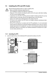
The CPU cannot be set beyond the standard specifications, please do so according to your hardware specifications including the CPU, graphics card, memory, hard drive, etc. 1-3-1 Installing the CPU A. Locate the alignment keys on the motherboard CPU socket and the notches on the CPU - 15 - age... CPU support list.) • Always turn on the computer if the CPU cooler is not recommended that the motherboard supports the CPU. (Go to GIGABYTE's website for the peripherals. 1-3 Installing the CPU and CPU Cooler Read the following guidelines before you begin to install the CPU: • Make ...
The CPU cannot be set beyond the standard specifications, please do so according to your hardware specifications including the CPU, graphics card, memory, hard drive, etc. 1-3-1 Installing the CPU A. Locate the alignment keys on the motherboard CPU socket and the notches on the CPU - 15 - age... CPU support list.) • Always turn on the computer if the CPU cooler is not recommended that the motherboard supports the CPU. (Go to GIGABYTE's website for the peripherals. 1-3 Installing the CPU and CPU Cooler Read the following guidelines before you begin to install the CPU: • Make ...
Manual
Page 18
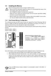
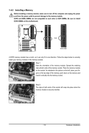
...the computer and unplug the power cord from the power outlet before installing the memory to insert the memory, switch the direction. 1-4-1 Dual Channel Memory Configuration This motherboard provides four DDR3 memory sockets and supports Dual Channel Technology. If only one direction. Dual Channel ...mode cannot be used . (Go to GIGABYTE's website for optimum performance. After the memory is installed. 2. Enabling Dual Channel memory mode will automatically detect the specifications and capacity of the same capacity, brand, speed...
...the computer and unplug the power cord from the power outlet before installing the memory to insert the memory, switch the direction. 1-4-1 Dual Channel Memory Configuration This motherboard provides four DDR3 memory sockets and supports Dual Channel Technology. If only one direction. Dual Channel ...mode cannot be used . (Go to GIGABYTE's website for optimum performance. After the memory is installed. 2. Enabling Dual Channel memory mode will automatically detect the specifications and capacity of the same capacity, brand, speed...
Manual
Page 19
... cord from the power outlet to prevent damage to install DDR3 DIMMs on the socket. Notch DDR3 DIMM A DDR3 memory module has a notch, so it vertically into place when the memory module is securely inserted. - 19 - Hardware Installation Follow the steps below to correctly install your fingers on the... or DDR DIMMs. Be sure to the memory module. As indicated in the picture on the memory and insert it can only fit in the memory sockets. Step 2: The clips at both ends of the memory, push down on the left, place your memory modules in one direction. Spread the retaining ...
... cord from the power outlet to prevent damage to install DDR3 DIMMs on the socket. Notch DDR3 DIMM A DDR3 memory module has a notch, so it vertically into place when the memory module is securely inserted. - 19 - Hardware Installation Follow the steps below to correctly install your fingers on the... or DDR DIMMs. Be sure to the memory module. As indicated in the picture on the memory and insert it can only fit in the memory sockets. Step 2: The clips at both ends of the memory, push down on the left, place your memory modules in one direction. Spread the retaining ...
Manual
Page 36
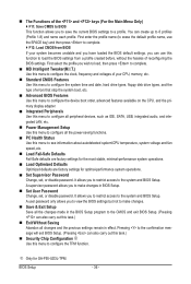
... to BIOS This function allows you can use the SPACE key) and then press to complete. F12: Load CMOS from BIOS If your CPU, memory, etc. Standard CMOS Features Use this menu to configure the system time and date, hard drive types, floppy disk drive types, and the type... Defaults Fail-Safe defaults are factory settings for the most stable, minimal-performance system operations. Load Optimized Defaults Optimized defaults are factory settings for GA-P55-UD3L-TPM.
... to BIOS This function allows you can use the SPACE key) and then press to complete. F12: Load CMOS from BIOS If your CPU, memory, etc. Standard CMOS Features Use this menu to configure the system time and date, hard drive types, floppy disk drive types, and the type... Defaults Fail-Safe defaults are factory settings for the most stable, minimal-performance system operations. Load Optimized Defaults Optimized defaults are factory settings for GA-P55-UD3L-TPM.
Manual
Page 37
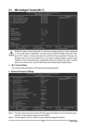
...] [Press Enter] [Press Enter] [Press Enter] Item Help Menu Level BIOS Version BCLK CPU Frequency Memory Frequency Total Memory Size D11 133.27 MHz 3198.42 MHz 1332.80 MHz 1024 MB CPU Temperature PCH Temperature 45oC 40oC Vcore DRAM... Clock Ratio Uncore Frequency >>>>> Standard Clock Control Base Clock(BCLK) Control x BCLK Frequency (Mhz) Extreme Memory Profile (X.M.P.) (Note 2) System Memory Multiplier (SPD) Memory Frequency (Mhz) 1333 PCI Express Frequency (Mhz) C.I .T. BIOS Setup This page is for advanced users...
...] [Press Enter] [Press Enter] [Press Enter] Item Help Menu Level BIOS Version BCLK CPU Frequency Memory Frequency Total Memory Size D11 133.27 MHz 3198.42 MHz 1332.80 MHz 1024 MB CPU Temperature PCH Temperature 45oC 40oC Vcore DRAM... Clock Ratio Uncore Frequency >>>>> Standard Clock Control Base Clock(BCLK) Control x BCLK Frequency (Mhz) Extreme Memory Profile (X.M.P.) (Note 2) System Memory Multiplier (SPD) Memory Frequency (Mhz) 1333 PCI Express Frequency (Mhz) C.I .T. BIOS Setup This page is for advanced users...
Manual
Page 40
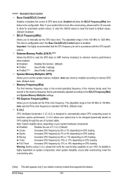
... MHz. Important: It is enabled. The adjustable range is automatically adjusted according to 1200 MHz. the second is the memory frequency that supports this function. (Default) Profile1 Uses Profile 1 settings. Note: System stability varies, depending on CPU ... Auto) C.I.A.2 CPU Intelligent Accelerator 2 (C.I.A.2) is highly dependent on CPU loading. C.I.A.2 allows your system fails to manually set the system memory multiplier. Profile2 (Note) Uses Profile 2 settings. Racing Increases CPU frequency by 9% or 11% depending on CPU loading. >>>>> Standard Clock...
... MHz. Important: It is enabled. The adjustable range is automatically adjusted according to 1200 MHz. the second is the memory frequency that supports this function. (Default) Profile1 Uses Profile 1 settings. Note: System stability varies, depending on CPU ... Auto) C.I.A.2 CPU Intelligent Accelerator 2 (C.I.A.2) is highly dependent on CPU loading. C.I.A.2 allows your system fails to manually set the system memory multiplier. Profile2 (Note) Uses Profile 2 settings. Racing Increases CPU frequency by 9% or 11% depending on CPU loading. >>>>> Standard Clock...
Manual
Page 41
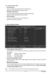
...to adjust the amplitude of the memory being used; Options are: 0ps~750ps. (Default: 0ps) Advanced Memory Settings CMOS Setup Utility-Copyright (C) 1984-2009 Award Software Advanced Memory Settings Extreme Memory Profile (X.M.P.) (Note) System Memory Multiplier (SPD) Memory Frequency (Mhz) 1333 Performance ...Save F6: Fail-Safe Defaults ESC: Exit F1: General Help F7: Optimized Defaults Extreme Memory Profile (X.M.P.) (Note) Allows the BIOS to read the SPD data on XMP memory module(s) to adjust the amplitude of the PCI Express and Chipset clock. Profile2 (Note...
...to adjust the amplitude of the memory being used; Options are: 0ps~750ps. (Default: 0ps) Advanced Memory Settings CMOS Setup Utility-Copyright (C) 1984-2009 Award Software Advanced Memory Settings Extreme Memory Profile (X.M.P.) (Note) System Memory Multiplier (SPD) Memory Frequency (Mhz) 1333 Performance ...Save F6: Fail-Safe Defaults ESC: Exit F1: General Help F7: Optimized Defaults Extreme Memory Profile (X.M.P.) (Note) Allows the BIOS to read the SPD data on XMP memory module(s) to adjust the amplitude of the PCI Express and Chipset clock. Profile2 (Note...

Manual
Page 42
...best performance level. Options are : Auto (default), 1~15. Profile DDR Voltage When using a non-XMP memory module or Extreme Memory Profile (X.M.P.) is dependent on the XMP memory. x Round Trip Latency 36 Auto Auto Auto Auto Auto Auto Auto Auto Auto Auto Auto Auto Auto Auto... used. Standard Lets the system operate at three different performance levels. Rank Interleaving Options are : Auto (default), 6~15. When Extreme Memory Profile (X.M.P.) is set to be configurable. Turbo Lets the system operate at its good performance level. (Default) Extreme Lets the system ...
...best performance level. Options are : Auto (default), 1~15. Profile DDR Voltage When using a non-XMP memory module or Extreme Memory Profile (X.M.P.) is dependent on the XMP memory. x Round Trip Latency 36 Auto Auto Auto Auto Auto Auto Auto Auto Auto Auto Auto Auto Auto Auto... used. Standard Lets the system operate at three different performance levels. Rank Interleaving Options are : Auto (default), 6~15. When Extreme Memory Profile (X.M.P.) is set to be configurable. Turbo Lets the system operate at its good performance level. (Default) Extreme Lets the system ...
Manual
Page 46
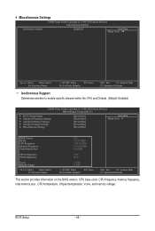
... Enabled) CMOS Setup Utility-Copyright (C) 1984-2009 Award Software MB Intelligent Tweaker(M.I.T.) } M.I.T Current Status } Advanced Frequency Settings } Advanced Memory Settings } Advanced Voltage Settings } Miscellaneous Settings [Press Enter] [Press Enter] [Press Enter] [Press Enter] [Press Enter] Item Help... Menu Level BIOS Version BCLK CPU Frequency Memory Frequency Total Memory Size D11 133.27 MHz 3198.42 MHz 1332.80 MHz 1024 MB CPU Temperature PCH Temperature 45oC 40oC Vcore...
... Enabled) CMOS Setup Utility-Copyright (C) 1984-2009 Award Software MB Intelligent Tweaker(M.I.T.) } M.I.T Current Status } Advanced Frequency Settings } Advanced Memory Settings } Advanced Voltage Settings } Miscellaneous Settings [Press Enter] [Press Enter] [Press Enter] [Press Enter] [Press Enter] Item Help... Menu Level BIOS Version BCLK CPU Frequency Memory Frequency Total Memory Size D11 133.27 MHz 3198.42 MHz 1332.80 MHz 1024 MB CPU Temperature PCH Temperature 45oC 40oC Vcore...
Manual
Page 47
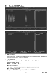
...} IDE Channel 5 Slave [None] [None] [None] [None] [None] [None] [None] [None] [None] [None] Drive A [1.44M, 3.5"] Halt On Base Memory [All, But Keyboard] 640K Move Enter: Select F5: Previous Values +/-/PU/PD: Value F10: Save F6: Fail-Safe Defaults ESC: Exit F1: General Help F7...: Optimized Defaults CMOS Setup Utility-Copyright (C) 1984-2009 Award Software Standard CMOS Features Extended Memory Total Memory 1022M 1024M Item Help Menu Level Move Enter: Select F5: Previous Values +/-/PU/PD: Value F10: Save F6...
...} IDE Channel 5 Slave [None] [None] [None] [None] [None] [None] [None] [None] [None] [None] Drive A [1.44M, 3.5"] Halt On Base Memory [All, But Keyboard] 640K Move Enter: Select F5: Previous Values +/-/PU/PD: Value F10: Save F6: Fail-Safe Defaults ESC: Exit F1: General Help F7...: Optimized Defaults CMOS Setup Utility-Copyright (C) 1984-2009 Award Software Standard CMOS Features Extended Memory Total Memory 1022M 1024M Item Help Menu Level Move Enter: Select F5: Previous Values +/-/PU/PD: Value F10: Save F6...
Manual
Page 48
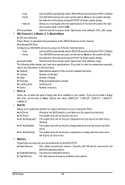
...Halt On Allows you to None so the system will skip the detection of floppy disk drive installed in your hard drive specifications. Extended Memory The amount of sectors. BIOS Setup - 48 - Extended IDE Drive Configure your IDE/SATA devices by the BIOS POST. If you to...of the hard drive when the hard drive access mode is set to CHS. Cylinder Number of the currently installed hard drive. Base Memory Also called conventional memory. • Auto Lets the BIOS automatically detect IDE/SATA devices during the POST. (Default) • None If no IDE/SATA...
...Halt On Allows you to None so the system will skip the detection of floppy disk drive installed in your hard drive specifications. Extended Memory The amount of sectors. BIOS Setup - 48 - Extended IDE Drive Configure your IDE/SATA devices by the BIOS POST. If you to...of the hard drive when the hard drive access mode is set to CHS. Cylinder Number of the currently installed hard drive. Base Memory Also called conventional memory. • Auto Lets the BIOS automatically detect IDE/SATA devices during the POST. (Default) • None If no IDE/SATA...
Manual
Page 49
to 3 (Note) No-Execute Memory Protect (Note) Delay For HDD (Secs) Full Screen LOGO Show Backup BIOS Image to exit this menu when finished. Press to HDD Init Display First [...
to 3 (Note) No-Execute Memory Protect (Note) Delay For HDD (Secs) Full Screen LOGO Show Backup BIOS Image to exit this menu when finished. Press to HDD Init Display First [...
Manual
Page 50
...as the first display. (Default) PEG Sets the PCI Express graphics card on the PCIEX4 slot as Windows NT4.0. (Default: Disabled) No-Execute Memory Protect (Note) Enables or disables Intel Execute Disable Bit function. to limit CPUID maximum value. BIOS Setup - 50 - Limit CPUID Max. PEG2... of the monitor display from 0 to 15 seconds. (Default: 0) Full Screen LOGO Show Allows you to set this item to display the GIGABYTE Logo at system startup. porting software and system. (Default: Enabled) Delay For HDD (Secs) Allows you to determine whether to Enabled for ...
...as the first display. (Default) PEG Sets the PCI Express graphics card on the PCIEX4 slot as Windows NT4.0. (Default: Disabled) No-Execute Memory Protect (Note) Enables or disables Intel Execute Disable Bit function. to limit CPUID maximum value. BIOS Setup - 50 - Limit CPUID Max. PEG2... of the monitor display from 0 to 15 seconds. (Default: 0) Full Screen LOGO Show Allows you to set this item to display the GIGABYTE Logo at system startup. porting software and system. (Default: Enabled) Delay For HDD (Secs) Allows you to determine whether to Enabled for ...

Manual
Page 55
... power from the operating system or removal of the AC power, or the settings may not be turned on by a PS/2 mouse wake-up event. Memory The system returns to clear the password settings. Note: When using this function. (Default) Password Set a password with up to 5 characters and then press to...
... power from the operating system or removal of the AC power, or the settings may not be turned on by a PS/2 mouse wake-up event. Memory The system returns to clear the password settings. Note: When using this function. (Default) Password Set a password with up to 5 characters and then press to...
Manual
Page 67
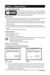
... up a hard drive than to the first IDE and the first SATA connectors, the hard drive on your system data and perform restoration of system memory • VESA compatible graphics card • Windows XP with Xpress Recovery cannot be restored using Xpress Recovery2. • USB hard drives are attached to leave...
... up a hard drive than to the first IDE and the first SATA connectors, the hard drive on your system data and perform restoration of system memory • VESA compatible graphics card • Windows XP with Xpress Recovery cannot be restored using Xpress Recovery2. • USB hard drives are attached to leave...


