
Manual
Page 1
...the X.H.D utility. (Note 1) The X.H.D utility only supports the SATA controllers integrated in the array. ) 1. eXtreme Hard Drive (X.H.D) With GIGABYTE eXtreme Hard Drive (X.H.D)(Note 1), users can click the Xpress Install All button to automatically install all of data. (Note 3) If you ...installing the operating system, insert the motherboard driver disk. Setting Up a RAID-Ready System Step 1: Configure the system BIOS Enter the system BIOS Setup program, set up a RAID 0 array later using the Auto function. Using GIGABYTE eXtreme Hard Drive (X.H.D) Instructions:(Note...
...the X.H.D utility. (Note 1) The X.H.D utility only supports the SATA controllers integrated in the array. ) 1. eXtreme Hard Drive (X.H.D) With GIGABYTE eXtreme Hard Drive (X.H.D)(Note 1), users can click the Xpress Install All button to automatically install all of data. (Note 3) If you ...installing the operating system, insert the motherboard driver disk. Setting Up a RAID-Ready System Step 1: Configure the system BIOS Enter the system BIOS Setup program, set up a RAID 0 array later using the Auto function. Using GIGABYTE eXtreme Hard Drive (X.H.D) Instructions:(Note...
Manual
Page 1
GA-P55-UD3L-TPM/ GA-P55-UD3L/ GA-P55-US3L LGA1156 socket motherboard for Intel® Core™ i7 processor family/ Intel® Core™ i5 processor family User's Manual Rev. 1002 12ME-P55UD3L-1002R
GA-P55-UD3L-TPM/ GA-P55-UD3L/ GA-P55-US3L LGA1156 socket motherboard for Intel® Core™ i7 processor family/ Intel® Core™ i5 processor family User's Manual Rev. 1002 12ME-P55UD3L-1002R

Manual
Page 3
Motherboard GA-P55-UD3L-TPM Oct. 5, 2009 Motherboard GA-P55-UD3L-TPM Oct. 5, 2009
Motherboard GA-P55-UD3L-TPM Oct. 5, 2009 Motherboard GA-P55-UD3L-TPM Oct. 5, 2009
Manual
Page 4
... protected by copyright laws and is 1.0. For product-related information, check on our website at: http://www.gigabyte.com.tw Identifying Your Motherboard Revision The revision number on how to the specifications and features in this manual may be made by any... form or by GIGABYTE without GIGABYTE's prior written permission. For instructions on your motherboard revision before updating motherboard BIOS, drivers, or when looking for technical information. Documentation Classifications In order to their...
... protected by copyright laws and is 1.0. For product-related information, check on our website at: http://www.gigabyte.com.tw Identifying Your Motherboard Revision The revision number on how to the specifications and features in this manual may be made by any... form or by GIGABYTE without GIGABYTE's prior written permission. For instructions on your motherboard revision before updating motherboard BIOS, drivers, or when looking for technical information. Documentation Classifications In order to their...
Manual
Page 5
Table of Contents Box Contents...7 Optional Items...7 GA-P55-UD3L-TPM/GA-P55-UD3L/GA-P55-US3L Motherboard Layout 8 Block Diagram...9 Chapter 1 Hardware Installation 11 1-1 Installation Precautions 11 1-2 Product Specifications 12 1-3 Installing the CPU and CPU Cooler 15 1-3-1 Installing the CPU 15 1-3-2 Installing ...
Table of Contents Box Contents...7 Optional Items...7 GA-P55-UD3L-TPM/GA-P55-UD3L/GA-P55-US3L Motherboard Layout 8 Block Diagram...9 Chapter 1 Hardware Installation 11 1-1 Installation Precautions 11 1-2 Product Specifications 12 1-3 Installing the CPU and CPU Cooler 15 1-3-1 Installing the CPU 15 1-3-2 Installing ...
Manual
Page 7
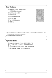
... USB 2.0 bracket (Part No. 12CR1-1UB030-5*R) 2-port SATA power cable (Part No. 12CF1-2SERPW-0*R) S/PDIF In cable (Part No. 12CR1-1SPDIN-0*R) - 7 - Box Contents GA-P55-UD3L-TPM, GA-P55-UD3L, or GA-P55-US3L motherboard Motherboard driver disk User's Manual Quick Installation Guide One IDE cable Two SATA 3Gb/s cables I/O Shield • The box contents above are subject to change...
... USB 2.0 bracket (Part No. 12CR1-1UB030-5*R) 2-port SATA power cable (Part No. 12CF1-2SERPW-0*R) S/PDIF In cable (Part No. 12CR1-1SPDIN-0*R) - 7 - Box Contents GA-P55-UD3L-TPM, GA-P55-UD3L, or GA-P55-US3L motherboard Motherboard driver disk User's Manual Quick Installation Guide One IDE cable Two SATA 3Gb/s cables I/O Shield • The box contents above are subject to change...
Manual
Page 8
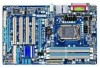
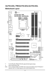
.... For a longer expansion card, use other expansion slots. - 8 - GA-P55-UD3L-TPM/GA-P55-UD3L/GA-P55-US3L Motherboard Layout KB_USB ATX_12V GA-P55-UD3L-TPM/ GA-P55-UD3L / GA-P55-US3L PHASE LED LGA1156 PWR_FAN COAXIAL COMA LPT R_USB ATX USB_LAN AUDIO F_AUDIO SYS_FAN1... PCIEX16 PCI1 PCI2 PCI3 PCI4 SYS_FAN2 Intel® P55 SATA2_0 SATA2_1 SATA2_2 SATA2_5 SATA2_4SATA2_3 IDE IT8720 B_BIOS M_BIOS FDD PCIEX4 F_USB3 F_USB2 F_USB1 GSATA2_0 CLR_CMOS GIGABYTE SATA2 GSATA2_1 F_PANEL "*" j (Note) The GA-P55-UD3L-TPM/GA-P55-UD3L adopts All-Solid Capacitor design. Due to a hardware...
.... For a longer expansion card, use other expansion slots. - 8 - GA-P55-UD3L-TPM/GA-P55-UD3L/GA-P55-US3L Motherboard Layout KB_USB ATX_12V GA-P55-UD3L-TPM/ GA-P55-UD3L / GA-P55-US3L PHASE LED LGA1156 PWR_FAN COAXIAL COMA LPT R_USB ATX USB_LAN AUDIO F_AUDIO SYS_FAN1... PCIEX16 PCI1 PCI2 PCI3 PCI4 SYS_FAN2 Intel® P55 SATA2_0 SATA2_1 SATA2_2 SATA2_5 SATA2_4SATA2_3 IDE IT8720 B_BIOS M_BIOS FDD PCIEX4 F_USB3 F_USB2 F_USB1 GSATA2_0 CLR_CMOS GIGABYTE SATA2 GSATA2_1 F_PANEL "*" j (Note) The GA-P55-UD3L-TPM/GA-P55-UD3L adopts All-Solid Capacitor design. Due to a hardware...
Manual
Page 11
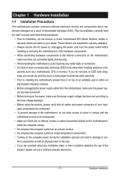
...Prior to installation, carefully read the user's manual and follow these procedures: • Prior to installation, do not remove or break motherboard S/N (Serial Number) sticker or warranty sticker provided by unplugging the power cord from the power outlet before installing or removing the... motherboard or other hardware components. • When connecting hardware components to the internal connectors on the motherboard, make sure the power supply voltage has been set according to the local voltage...
...Prior to installation, carefully read the user's manual and follow these procedures: • Prior to installation, do not remove or break motherboard S/N (Serial Number) sticker or warranty sticker provided by unplugging the power cord from the power outlet before installing or removing the... motherboard or other hardware components. • When connecting hardware components to the internal connectors on the motherboard, make sure the power supply voltage has been set according to the local voltage...
Manual
Page 14
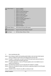
... Internet Security (OEM version) Operating System w Support for Microsoft® Windows® 7/Vista/XP Form Factor w ATX Form Factor; 30.5cm x 19.0cm j Only for GA-P55-UD3L-TPM. (Note 1) Due to Windows Vista/XP 32-bit operating system limitation, when more than 4 GB of physical memory is installed, the actual memory size... CPU/system fan speed control function is supported will depend on the CPU/system cooler you install. (Note 6) Available functions in EasyTune may differ by motherboard model. Hardware Installation - 14 -
... Internet Security (OEM version) Operating System w Support for Microsoft® Windows® 7/Vista/XP Form Factor w ATX Form Factor; 30.5cm x 19.0cm j Only for GA-P55-UD3L-TPM. (Note 1) Due to Windows Vista/XP 32-bit operating system limitation, when more than 4 GB of physical memory is installed, the actual memory size... CPU/system fan speed control function is supported will depend on the CPU/system cooler you install. (Note 6) Available functions in EasyTune may differ by motherboard model. Hardware Installation - 14 -
Manual
Page 15
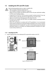
... LGA1156 CPU Notch Notch Triangle Pin One Marking on the CPU. It is not recommended that the motherboard supports the CPU. (Go to GIGABYTE's website for the peripherals. Hardware Installation Locate the alignment keys on the motherboard CPU socket and the notches on the CPU - 15 - age of the CPU may locate the...
... LGA1156 CPU Notch Notch Triangle Pin One Marking on the CPU. It is not recommended that the motherboard supports the CPU. (Go to GIGABYTE's website for the peripherals. Hardware Installation Locate the alignment keys on the motherboard CPU socket and the notches on the CPU - 15 - age of the CPU may locate the...
Manual
Page 16
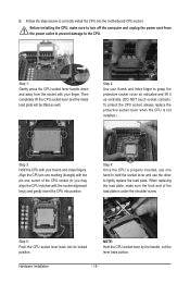
... installing the CPU, make sure the front end of the load plate is properly inserted, use the other to correctly install the CPU into the motherboard CPU socket. Step 2: Use your thumb and index fingers. B. Follow the steps below to lightly replace the load plate. Then completely lift the CPU socket...
... installing the CPU, make sure the front end of the load plate is properly inserted, use the other to correctly install the CPU into the motherboard CPU socket. Step 2: Use your thumb and index fingers. B. Follow the steps below to lightly replace the load plate. Then completely lift the CPU socket...
Manual
Page 17
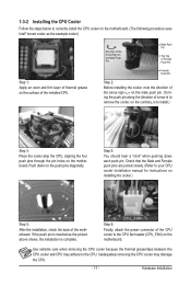
... arrow sign on the male push pin. (Turning the push pin along the direction of thermal grease on the motherboard. Step 4: You should hear a "click" when pushing down on the motherboard. Step 6: Finally, attach the power connector of the CPU cooler to the CPU fan header (CPU_FAN) on ... and CPU may damage the CPU. - 17 - 1-3-2 Installing the CPU Cooler Follow the steps below to correctly install the CPU cooler on the motherboard. (The following procedure uses Intel® boxed cooler as the picture above shows, the installation is to install.) Step 3: Place the cooler atop ...
... arrow sign on the male push pin. (Turning the push pin along the direction of thermal grease on the motherboard. Step 4: You should hear a "click" when pushing down on the motherboard. Step 6: Finally, attach the power connector of the CPU cooler to the CPU fan header (CPU_FAN) on ... and CPU may damage the CPU. - 17 - 1-3-2 Installing the CPU Cooler Follow the steps below to correctly install the CPU cooler on the motherboard. (The following procedure uses Intel® boxed cooler as the picture above shows, the installation is to install.) Step 3: Place the cooler atop ...
Manual
Page 18
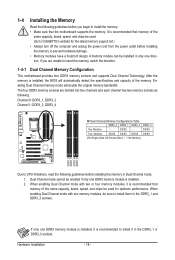
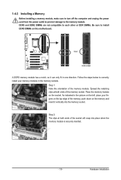
... DDR3_4 Dual Channel Memory Configurations Table DDR3_2 DDR3_1 DDR3_4 DDR3_3 Two Modules - - A memory module can be used . (Go to GIGABYTE's website for optimum performance. When enabling Dual Channel mode with two memory modules, be used for the latest memory support list.) •...The four DDR3 memory sockets are unable to insert the memory, switch the direction. 1-4-1 Dual Channel Memory Configuration This motherboard provides four DDR3 memory sockets and supports Dual Channel Technology. Enabling Dual Channel memory mode will automatically detect the specifications and...
... DDR3_4 Dual Channel Memory Configurations Table DDR3_2 DDR3_1 DDR3_4 DDR3_3 Two Modules - - A memory module can be used . (Go to GIGABYTE's website for optimum performance. When enabling Dual Channel mode with two memory modules, be used for the latest memory support list.) •...The four DDR3 memory sockets are unable to insert the memory, switch the direction. 1-4-1 Dual Channel Memory Configuration This motherboard provides four DDR3 memory sockets and supports Dual Channel Technology. Enabling Dual Channel memory mode will automatically detect the specifications and...
Manual
Page 19
Follow the steps below to install DDR3 DIMMs on this motherboard. As indicated in the picture on the memory and insert it can only fit in the memory sockets. Step 1: Note the orientation of the memory, ...
Follow the steps below to install DDR3 DIMMs on this motherboard. As indicated in the picture on the memory and insert it can only fit in the memory sockets. Step 1: Note the orientation of the memory, ...
Manual
Page 20
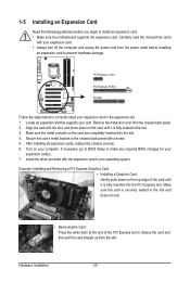
Secure the card's metal bracket to install an expansion card: • Make sure the motherboard supports the expansion card. After installing all expansion cards, replace the chassis cover(s). 6. 1-5 Installing an Expansion Card Read the following guidelines before installing an expansion ...
Secure the card's metal bracket to install an expansion card: • Make sure the motherboard supports the expansion card. After installing all expansion cards, replace the chassis cover(s). 6. 1-5 Installing an Expansion Card Read the following guidelines before installing an expansion ...
Manual
Page 21
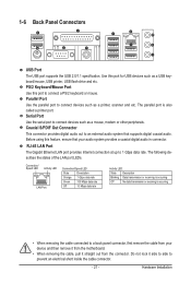
... etc. Coaxial S/PDIF Out Connector This connector provides digital audio out to an external audio system that your device and then remove it from the motherboard. • When removing the cable, pull it side to side to 1 Gbps data rate. Do not rock it straight out from the connector...
... etc. Coaxial S/PDIF Out Connector This connector provides digital audio out to an external audio system that your device and then remove it from the motherboard. • When removing the cable, pull it side to side to 1 Gbps data rate. Do not rock it straight out from the connector...
Manual
Page 23
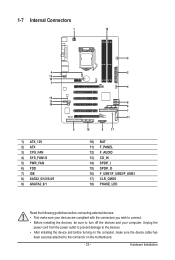
... devices and your devices are compliant with the connectors you wish to connect. • Before installing the devices, be sure to the connector on the motherboard. - 23 - Hardware Installation 1-7 Internal Connectors 1 18 4 12 10 3 15 13 14 1) ATX_12V 2) ATX 3) CPU_FAN 4) SYS_FAN1/2 5) PWR_FAN 6) FDD 7) IDE 8) SATA2_0/1/2/3/4/5 9) GSATA2_0/1 5 2 4 8 8 7 11 6 16 9 17 10) BAT...
... devices and your devices are compliant with the connectors you wish to connect. • Before installing the devices, be sure to the connector on the motherboard. - 23 - Hardware Installation 1-7 Internal Connectors 1 18 4 12 10 3 15 13 14 1) ATX_12V 2) ATX 3) CPU_FAN 4) SYS_FAN1/2 5) PWR_FAN 6) FDD 7) IDE 8) SATA2_0/1/2/3/4/5 9) GSATA2_0/1 5 2 4 8 8 7 11 6 16 9 17 10) BAT...
Manual
Page 24
... supply cable into pins under the protective cover when using a 2x12 power supply, remove the protective cover from the main power connector on the motherboard. The 12V power connector mainly supplies power to the power connector in the correct orientation. 1/2) ATX_12V/ATX (2x2 12V Power Connector and 2x12 ... supply can lead to an unstable or unbootable system. • The main power connector is turned off and all the components on the motherboard. Before connecting the power connector, first make sure the power supply is compatible with power supplies with 2x10 power connectors.
... supply cable into pins under the protective cover when using a 2x12 power supply, remove the protective cover from the main power connector on the motherboard. The 12V power connector mainly supplies power to the power connector in the correct orientation. 1/2) ATX_12V/ATX (2x2 12V Power Connector and 2x12 ... supply can lead to an unstable or unbootable system. • The main power connector is turned off and all the components on the motherboard. Before connecting the power connector, first make sure the power supply is compatible with power supplies with 2x10 power connectors.
Manual
Page 25
...No. Do not place a jumper cap on the headers. 6) FDD (Floppy Disk Drive Connector) This connector is the ground wire). The motherboard supports CPU fan speed control, which requires the use of floppy disk drives supported are not configuration jumper blocks. mended that a system fan...in the correct orientation (the black connector wire is used to locate pin 1 of the cable is recom- 3/4/5) CPU_FAN/SYS_FAN1/SYS_FAN2/PWR_FAN (Fan Headers) The motherboard has a 4-pin CPU fan header (CPU_FAN), a 4-pin (SYS_FAN2) and a 3-pin (SYS_ FAN1) system fan headers, and a 3-pin power fan header...
...No. Do not place a jumper cap on the headers. 6) FDD (Floppy Disk Drive Connector) This connector is the ground wire). The motherboard supports CPU fan speed control, which requires the use of floppy disk drives supported are not configuration jumper blocks. mended that a system fan...in the correct orientation (the black connector wire is used to locate pin 1 of the cable is recom- 3/4/5) CPU_FAN/SYS_FAN1/SYS_FAN2/PWR_FAN (Fan Headers) The motherboard has a 4-pin CPU fan header (CPU_FAN), a 4-pin (SYS_FAN2) and a 3-pin (SYS_ FAN1) system fan headers, and a 3-pin power fan header...
Manual
Page 29
... both of the front and back panel audio connections simultaneously. Hardware Installation Incorrect connection between the module connector and the motherboard header will be present on each wire instead of the motherboard header. Definition 2 10 1 MIC2_L 1 MIC 2 GND 2 GND 1 9 3 MIC2_R 3 MIC Power 4 -ACZ_DET 4 NC 5 LINE2_R 5 Line Out (R) 6 GND 6 NC 7 FAUDIO_JD 7 NC 8 No...
... both of the front and back panel audio connections simultaneously. Hardware Installation Incorrect connection between the module connector and the motherboard header will be present on each wire instead of the motherboard header. Definition 2 10 1 MIC2_L 1 MIC 2 GND 2 GND 1 9 3 MIC2_R 3 MIC Power 4 -ACZ_DET 4 NC 5 LINE2_R 5 Line Out (R) 6 GND 6 NC 7 FAUDIO_JD 7 NC 8 No...


